FANUC Series 30i/300i/300is-MODEL A. Machining Center System. User's manual - page 243
 

  Index      Manuals     FANUC Series 30i/300i/300is-MODEL A. Machining Center System. User's manual (B-63944EN/03)


Search            copyright infringement  


Content      ..     241      242      243      244     ..


FANUC Series 30i/300i/300is-MODEL A. Machining Center System. User's manual - page 243


13

.

GRAPHIC

 FUNCTION

 OPERATION 

B-63944EN/03


- 1900 - 

13.1 

GRAPHIC DISPLAY 

 
The graphic display functions enable drawing of the tool path of the 
program currently used for machining. 
These functions are intended to display the movement of the tool 
during automatic operation or during manual operation. 
This enables the operator to check the progress of machining and the 
current tool position. 
These functions include the following: 


The current tool position in the workpiece coordinate system is 
displayed. 


Graphic coordinates can be set freely. 


Rapid traverse and cutting feed can be drawn using a different 
color for each. 


The values of F, S, and T in the program during drawing are 
displayed. 


Graphic enlargement or reduction is possible. 


Graphic display procedure 

Explanation 

Press the function key 

 then press the [GRAPH] soft key to 

display the tool path graphic screen. 
 

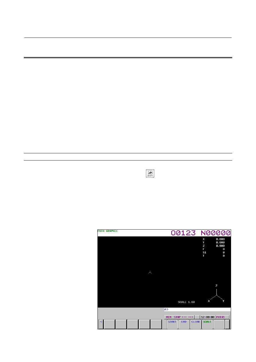
  - Tool path graphic screen 

The tool path graphic screen consists of three major areas: 


Graphic area for drawing a tool path 


Area for displaying machining information such as tool position 
information  


Area for displaying a graphic coordinate system 


Fig. 13.1 (a)    Tool path graphic screen (M series) 

B-63944EN/03

 OPERATION 

13.GRAPHIC FUNCTION


- 1901 - 


Fig. 13.1 (b)    Tool path graphic screen (T series) 


 - Tool path 

In a graphic coordinate system set by the graphic parameters described 
later, a tool path in the workpiece coordinate system is drawn. 
Even when the tool position changes discontinuously for a cause such 
as the setting of the origin and the switching of the workpiece 
coordinate system, drawing is performed assuming that the tool has 
moved. 
A tool path is continuously drawn even when the screen display is 
changed to another screen. 
 

 - Machining information 

On the right side of the screen, the positions (along only three axes 
used for drawing) in the workpiece coordinate system, feedrate (F), 
spindle speed (S), and tool number (T) are displayed. 
 

NOTE 


Up to three graphic axes are used with the M 
series, and up to two graphic axes are used with 
the T series. 


  - Graphic coordinate system 

On the lower-right portion of the screen, the coordinate axes and axis 
names of the graphic coordinate system are displayed. 
 

13

.

GRAPHIC

 FUNCTION

 OPERATION 

B-63944EN/03


- 1902 - 

Graphic parameter screen 


Explanation 

Press the function key 

 then press the [PARAM] soft key to 

display the tool path graphic screen. 
On the graphic parameter screen, make settings necessary for drawing 
a tool path. 
The graphic parameter screen consists of three pages. 
 

M


  - Graphic parameter screen page 1 


Fig. 13.1 (c)    Graphic parameter screen page 1 

 
On graphic parameter screen page 1, a graphic coordinate system, 
graphic range, and so forth are set. 
In the setting of a graphic coordinate system, the coordinate axes and 
axis names of the set coordinate system are graphically displayed.  
When a three-dimensional coordinate system is displayed, a rotation 
angle is also displayed. 
A graphic range is set using one of two methods.    One method sets a 
graphic scale and graphic center coordinates.  The other sets the 
maximum values and minimum values of a graphic range. 
 

B-63944EN/03

 OPERATION 

13.GRAPHIC FUNCTION


- 1903 - 

  - Graphic parameter screen page 2 


Fig. 13.1 (d)    Graphic parameter screen page 2 

 
On graphic parameter screen page 2, graphic colors, rotation angles, 
and whether to perform automatic erase operation are set. 
 

  - Graphic parameter screen page 3 


Fig. 13.1 (e)    Graphic parameter screen page 3 

 
On graphic parameter screen page 3, coordinate axes to be used for 
drawing are set. 
 

13

.

GRAPHIC

 FUNCTION

 OPERATION 

B-63944EN/03


- 1904 - 


T


  - Graphic parameter screen page 1 


Fig. 13.1 (f)    Graphic parameter screen page 1 

 
On graphic parameter screen page 1, a graphic coordinate system, 
graphic range, and so forth are set. 
In the setting of a graphic coordinate system, the coordinate axes and 
axis names of the set coordinate system are graphically displayed.  
When a three-dimensional coordinate system is displayed, a rotation 
angle is also displayed. 
A graphic range is set using one of two methods.    One method sets a 
graphic scale and graphic center coordinates.  The other sets the 
maximum values and minimum values of a graphic range. 
 

B-63944EN/03

 OPERATION 

13.GRAPHIC FUNCTION


- 1905 - 

  - Graphic parameter screen page 2 


Fig. 13.1 (g)    Graphic parameter screen page 2 (T series) 

 
On graphic parameter screen page 2, graphic colors and whether to 
perform automatic erase operation are set. 
 

  - Graphic parameter screen page 3 

Fig. 13.1 (h)    Graphic parameter screen page 3 

 
On graphic parameter screen page 3, coordinate axes to be used for 
drawing are set. 


13

.

GRAPHIC

 FUNCTION

 OPERATION 

B-63944EN/03


- 1906 - 

Graphic parameter setting 


Explanation 

For tool path drawing, a graphic coordinate system, tool path graphic 
colors, and graphic range need to be set on the graphic parameter 
screen. 
The graphic parameters to be set on the graphic parameter screen are 
described below. 
When a value is set for a parameter, the parameter value becomes 
immediately effective.    If a tool path is already drawn, the tool path 
is cleared when new parameter values are set. 
 

  - Graphic coordinate system 

Select a desired graphic coordinate system for tool path drawing then 
set the corresponding number. 
 

M


Y

X

0. XY

Z

Y

1. YZ

Z

2. ZY

Z

X

3. XZ

4. XYZ

Z

X

Y

5. ZXY

Z X


Fig. 13.1 (i)    Graphic coordinate system (M series) 


T


Setting = 0

Setting = 1

Setting = 2


Setting = 3

Setting = 4

Setting = 5

Setting = 6


Setting = 7

X

Z

Z

Z


Z

Z

Z

X

X

X

X

X


Fig. 13.1 (j)    Graphic coordinate system (T series) 

B-63944EN/03

 OPERATION 

13.GRAPHIC FUNCTION


- 1907 - 

M


  - Horizontal rotation angle 

When a three-dimensional graphic coordinate system such as 4.XYZ 
or 5.ZXY is selected, the coordinate system can be rotated with the 
horizontal plane used as the rotation plane.    Set a rotation angle from 
-360

°

 to +360

°

 
The initial rotation angle can be set with parameter No. 24831, and the 
actual rotation angle is equal to the "initial rotation angle + specified 
rotation angle". 
 
In Fig. 13.1 (k) below, the graphic coordinate system XYZ is 
converted to X”Y”Z” by the following settings: 
 

Initial rotation angle:    180

°


Horizontal rotation angle:    30

°


Y


X

Z

180

°


X'


Y'

X"

Y"

Horizontal 
rotation plane


30

°


Fig. 13.1 (k)    Coordinate system rotation in horizontal direction 


  - Vertical rotation angle 

When a three-dimensional coordinate system such as 4.XYZ or 
5.ZXY is selected, the coordinate system can be rotated with an axis 
on the horizontal plane specified as a vertical rotation axis.  Set a 
rotation angle from -360

°

 to +360

°

 
A vertical rotation axis can be set with the angle with the horizontal 
axis of the screen on the horizontal plane. This angle can be set with 
parameter No. 24832. 
 
In Fig. 13.1 (l) below, the graphic coordinate system XYZ is 
converted to X'Y'Z' by the following settings: 
 

Rotation angle of the vertical rotation axis:    65

°


Vertical rotation angle:    20

°


Content      ..     241      242      243      244     ..