FANUC Series 30i/300i/300is-MODEL A. Machining Center System. User's manual - page 185
 

  Index      Manuals     FANUC Series 30i/300i/300is-MODEL A. Machining Center System. User's manual (B-63944EN/03)


Search            copyright infringement  


Content      ..     183      184      185      186     ..


FANUC Series 30i/300i/300is-MODEL A. Machining Center System. User's manual - page 185


12.SETTING AND DISPLAYING DATA

 OPERATION 

B-63944EN/03


- 1436 - 

12.1.3 

Overall Position Display 

 
Displays the following positions on a screen : Current positions of the 
tool in the workpiece coordinate system, relative coordinate system, 
and machine coordinate system, and the remaining distance.   
The relative coordinates can also be set on this screen. See III-12.1.2 
for the procedure. 


Procedure for displaying overall position display screen 

Procedure 

Press function key 

Press soft key [ALL].   


Fig. 12.1.3 (a) Current position (overall) screen (M series) (10.4-inch) 


Fig. 12.1.3 (b) Current position (overall) screen (T series) (10.4-inch) 

B-63944EN/03

 OPERATION 

12.SETTING AND DISPLAYING DATA


- 1437 - 

Explanation 
 - Coordinate display 

The current positions of the tool in the following coordinate systems 
are displayed at the same time: 


Current position in the relative coordinate system   

 (relative 

coordinate) 


Current position in the workpiece coordinate system 

 (absolute 

coordinate) 


Current position in the machine coordinate system 

 (machine 

coordinate) 


Distance to go (distance to go) 


  - Distance to go 

The distance remaining is displayed in the MEMORY or MDI mode.   
The distance the tool is yet to be moved in the current block is 
displayed. 
 

  - Machine coordinate system 

The least command increment is used as the unit for values displayed 
in the machine coordinate system. However, the least input increment 
can be used by setting bit 0 (MCN) of parameter No. 3104. 
 

  - Resetting the relative coordinates 

The total position display screen also supports the resetting of the 
relative coordinates to 0 or presetting of them to specified values. See 
the procedure for resetting the relative coordinates described in 
Subsection III-12.1.2 
 

12.SETTING AND DISPLAYING DATA

 OPERATION 

B-63944EN/03


- 1438 - 

12.1.4 

Workpiece Coordinate System Preset 

 
If a workpiece coordinate system has been shifted with manual 
intervention or any other operation, an MDI operation can be 
performed to preset the system to a workpiece coordinate system that 
is offset by a workpiece origin offset, from the machine zero point that 
has been set before the shifting. 
A command (G92.1) can be programmed to preset a workpiece 
coordinate system. (See II-7.2.4.) 
 

Procedure for the workpiece coordinate system preset 

Procedure 

Press function key 

Press soft key [(OPRT)].   

Enter the axis name (

, ...) and 


Press soft key [PRESET].   


Explanation 
 - Operation mode 

This function can be executed when the reset state or automatic 
operation stop state is entered, regardless of the operation mode. 
 

  - Presetting relative coordinates 

As with absolute coordinates, bit 3 (PPD) of parameter No. 3104 is 
used to specify whether to preset relative coordinates (RELATIVE). 
 

B-63944EN/03

 OPERATION 

12.SETTING AND DISPLAYING DATA


- 1439 - 

12.1.5 

Actual Feedrate Display 

 
The actual feedrate on the machine (per minute) can be displayed on a 
current position display screen or program check screen.   
On the 12 soft keys display unit, the actual feedrate is always 
displayed. 
 

Display procedure for the actual feedrate on the current position display screen 

Procedure 

1  Press the function key 

 to display a current position 

display screen. At the location indicated by 

, an actual 

feedrate is displayed. 


Fig. 12.1.5 (a) Current position (absolute) screen (M series) (10.4-inch) 


12.SETTING AND DISPLAYING DATA

 OPERATION 

B-63944EN/03


- 1440 - 


Fig. 12.1.5 (b) Current position (absolute) screen (T series) (10.4-inch) 

 
The actual feedrate is displayed in units of millimeter/min or inch/min 
(depending on the specified least input increment) under the display of 
the current position. 
 

Explanation 
  - Actual feedrate value 

The actual rate is calculated by the following expression: 

=

n

1

i

2

(fi)

Fact


:  Number of axes 

fi 

:  Cutting feed rate in the tangential direction of 

each axis or rapid traverse rate 

Fact  :  Actual feedrate displayed 

The display unit: 
 

mm/min (metric input). 


inch/min (Inch input, two digits below the decimal point are 
displayed.) 


  - Actual feedrate display of feed per revolution 

In the case of feed per revolution and thread cutting, the actual 
feedrate displayed is the feed per minute rather than feed per 
revolution. 
 

  - Actual feedrate display of rotary axis 

In the case of movement of rotary axis, the speed is displayed in units 
of deg/min but is displayed on the screen in units of input system at 
that time. For example, when the rotary axis moves at 50 deg/min, the 
following is displayed: 50 mm/min (in metric input) or 0.50 inch/min 
(in inch input). 
 

  - Actual feedrate display on the other screen 

The program check screen also displays the actual feedrate. 
 

B-63944EN/03

 OPERATION 

12.SETTING AND DISPLAYING DATA


- 1441 - 

12.1.6 

Display of Run Time and Parts Count 

 
The run time, cycle time, and the number of machined parts are 
displayed on the current position display screens. 


Procedure for displaying run time and parts count on the current position display 
screen 

Procedure 

1  Press the function key 

 to display a current position 

display screen. At the location indicated by 

, a run time and 

parts count are displayed. 


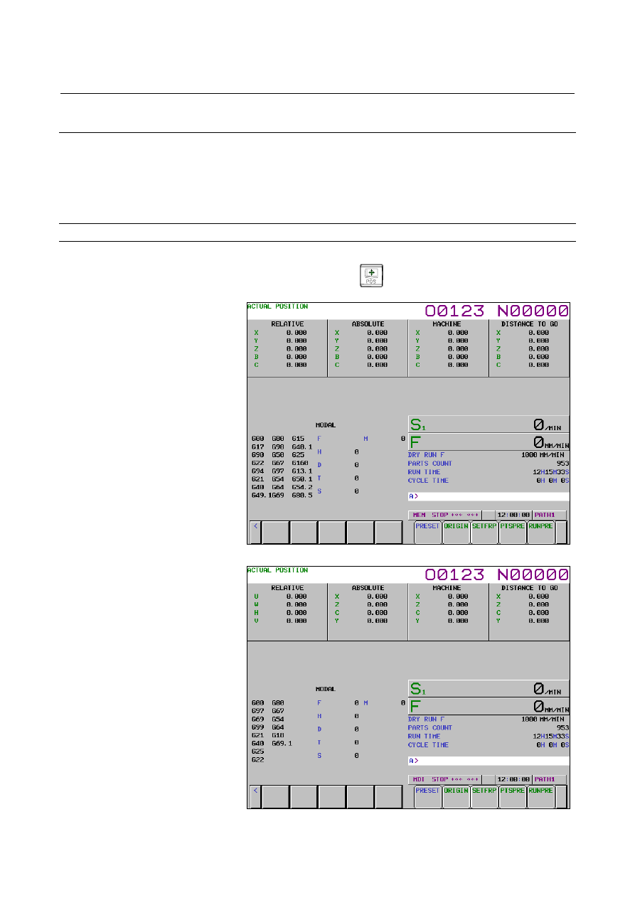
Fig. 12.1.6 (a) Current position (relative) screen (M series) (10.4-inch) 


Fig. 12.1.6 (b) Current position (relative) screen (T series) (10.4-inch) 

12.SETTING AND DISPLAYING DATA

 OPERATION 

B-63944EN/03


- 1442 - 

The number of machined parts (PART COUNT), run time (RUN 
TIME), and cycle time (CYCLE TIME) are displayed under the 
current position. 
 

Explanation 
 - PART COUNT 

Indicates the number of machined parts. The number is incremented 
each time M02, M30, or an M code specified by parameter No. 6710 
is executed. 
 

 - RUN TIME 

Indicates the total run time during automatic operation, excluding the 
stop and feed hold time. 
 

 - CYCLE TIME 

Indicates the run time of one automatic operation, excluding the stop 
and feed hold time. This is automatically preset to 0 when a cycle start 
is performed at reset state. It is preset to 0 even when power is 
removed. 
 

  - Display on the other screen 

Details of the run time and the number of machined parts are 
displayed on the setting screen. See III-12.3.3. 
 

 - Parameter setting 

The number of machined parts and run time cannot be set on current 
position display screens.   
The number of machined parts and run time cannot be set on current 
position display screens. They can be set by parameters Nos. 6711, 
6751, and 6752 or on the setting screen. 
 

  - Incrementing the number of machined parts 

Bit 0 (PCM) of parameter No. 6700 is used to specify whether the 
number of machined parts is incremented each time M02, M30, or an 
M code specified by parameter No. 6710 is executed, or only each 
time an M code specified by parameter No. 6710 is executed. 
 

B-63944EN/03

 OPERATION 

12.SETTING AND DISPLAYING DATA


- 1443 - 

12.1.7 

Setting the Floating Reference Position 

 
To perform floating reference position return with a G30.1 command, 
the floating reference position must be set beforehand. 
 

Procedure for setting the floating reference position 

Procedure 

Press function key 

  to display a screen used for displaying 

the current position.   

Move the tool to the floating reference position by jogging. 

Press soft key [(OPRT)].   

Press soft key [SET FRP].   

To register the floating reference positions for all axes, press soft 
key [ALL AXIS]. 


To register the floating reference position of a specific axis, enter 
the name of the axis (

, etc.), then press soft key 

[AXIS


NAME]. Two or more names can be entered consecutively 

(e.g., )


 [AXIS NAME]). 


The above operation stores the floating reference position. It can 
be checked with parameter (No. 1244). 

In step 4, the floating reference position along a specified axis 
can also be stored by entering the axis name (such as 

 or 

) and pressing soft key [SET FRP]. 


Explanation 
  - Presetting the relative coordinate system 

When bit 3 (FPC) of parameter No. 1201 is set to 1, the floating 
reference position can be registered, while the relative position display 
can be preset to 0. 


Content      ..     183      184      185      186     ..