FANUC Series 30i/300i/300is-MODEL A. Machining Center System. User's manual - page 129
 

  Index      Manuals     FANUC Series 30i/300i/300is-MODEL A. Machining Center System. User's manual (B-63944EN/03)


Search            copyright infringement  


Content      ..     127      128      129      130     ..


FANUC Series 30i/300i/300is-MODEL A. Machining Center System. User's manual - page 129


1.GENERAL

 OPERATION 

B-63944EN/03


- 988 - 

1.4 

TESTING A PROGRAM 

 
Before machining is started, the automatic running check can be 
executed.  
It checks whether the created program can operate the machine as 
desired.  
This check can be accomplished by running the machine actually or 
viewing the position display change (without running the machine) 
(See Section III-5). 
 

1.4.1 

Check by Running the Machine 


Explanation 
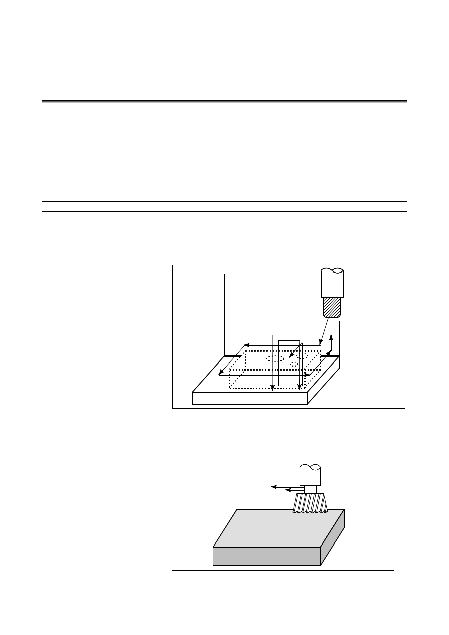
 - Dry run  

Remove the workpiece, check only movement of the tool. Select the 
tool movement rate using the dial on the operator's panel. (See Section 
III-5.4) 

Tool

Table


Fig. 1.4.1 (a)    Dry run 


 - Feedrate override 

Check the program by changing the feedrate specified in the program. 
(See Section III-5.2) 

Tool

Feedrate specified by program :
100 mm/min.

Feedrate after feed rate
override (20%) : 20 mm/min.

Workpiece


Fig. 1.4.1 (b)    Feedrate override 

B-63944EN/03

 OPERATION 

1.GENERAL


- 989 - 

 - Single block 

When the cycle start pushbutton is pressed, the tool executes one 
operation then stops. By pressing the cycle start again, the tool 
executes the next operation then stops. The program is checked in this 
manner. (See Section III-5.5) 


Tool

Cycle start

Stop 

Stop

Stop 

Workpiece

Cycle 
start 

Cycle 
start 

Cycle 
start 


Fig. 1.4.1 (c)    Single Block 


1.4.2 

How to View the Position Display Change without Running 

the Machine 


Explanation 
 - Machine Lock 

MDI

X

Y

Z

Tool

The tool remains stopped, and only the
positional displays of the axes change.

Workpiece


Fig. 1.4.2 (a)    Machine Lock 


  - Auxiliary function lock   

When automatic running is placed into the auxiliary function lock 
mode during the machine lock mode (See Sections III-5.1), all 
auxiliary functions (spindle rotation, tool replacement, coolant on/off, 
etc.) (See Section III-5.1) are disabled. 
 

1.GENERAL

 OPERATION 

B-63944EN/03


- 990 - 

1.5 

EDITING A PROGRAM 

 
After a created program is once registered in memory, it can be 
corrected or modified from the MDI panel (See Section III-10). 
This operation can be executed using the program edit function. 
 

B-63944EN/03

 OPERATION 

1.GENERAL


- 991 - 

1.6 

DISPLAYING AND SETTING DATA 

 
The operator can display or change a value stored in CNC internal 
memory by key operation on the MDI screen (See III-12). 

Data setting

Data display

Screen Keys

MDI

CNC memory


Fig. 1.6 (a)    Displaying and setting data 


Explanation 
 - Offset value 

Setting

Display

Screen  Keys

MDI

Geometry

Wear

compensation compensation

Tool compensation number 1   12.3

25.0

Tool compensation number 2   20.0

40.0

Tool compensation number 3

CNC memory


Fig. 1.6 (b)    Displaying and Setting Offset Values 

 
The tool has the tool dimension (length, diameter). When a workpiece 
is machined, the tool movement value depends on the tool dimensions. 
By setting tool dimension data in CNC memory beforehand, CNC 
automatically generates tool routes that permit any tool to cut the 
workpiece specified by the program. Tool dimension data is called the 
offset value. 

1.GENERAL

 OPERATION 

B-63944EN/03


- 992 - 

Machined
shape

2nd tool path

1st tool path

Offset value of the 1st tool

Offset value of the 2nd tool


Fig. 1.6 (c)    Offset value 


  - Displaying and setting operator's setting data 

Apart from parameters, there is data that is set by the operator in 
operation. This data causes machine characteristics to change. 
For example, the following data can be set: 

 Inch/Metric 

switching 


Selection of I/O devices 


Mirror image cutting on/off 

The above data is called setting data (See Section III-12.3.1). 

Setting

Screen Keys

MDI

Displaying

CNC Memory

Program

Automatic
operation

Movement of
the machine

Operational
characteristics

Setting data

Inch/Metric switching

Ì Ý

Selection of I/O device
Mirror image ON/OFF setting

:

:

:


Fig. 1.6 (d)    Displaying and setting operator's setting data 

B-63944EN/03

 OPERATION 

1.GENERAL


- 993 - 

  - Displaying and setting parameters 

The CNC functions have versatility in order to take action in 
characteristics of various machines. 
For example, CNC can specify the following: 

Rapid traverse rate of each axis 

Whether increment system is based on metric system or inch 
system. 

How to set command multiply/detect multiply (CMR/DMR) 

Data to make the above specification is called parameters (See Section 
III-12.4.1).  
Parameters differ depending on machine tool. 

Setting

Screen Keys

MDI

Display

CNC memory

Parameter
Rapid traverse rate
Position control
Reference position return
Backlash compensation data
Pitch error compensation data

:

:

:

Program

Automatic
operation

Movement of
the machine

Operational
characteristics


Fig. 1.6 (e)    Displaying and setting parameters 


  - Data protection key 

A key called the data protection key can be defined. It is used to 
prevent part programs, offset values, parameters, and setting data from 
being registered, modified, or deleted erroneously (See Section 
III-12). 

Program
Offset value
Parameters
Setting data

Data Setting

Machine
operator's panel

Screen Keys

 Data protection key

MDI

Signal

Data protection key

Registration / modification inhibition

CNC memory


Fig. 1.6 (f)    Data protection key 

1.GENERAL

 OPERATION 

B-63944EN/03


- 994 - 

1.7 

DISPLAY 


1.7.1 

Program Display 

 
The contents of the currently active program are displayed. 
(See Section III-12.2.1) 


Fig. 1.7.1 (a)     

 
A list of the programs held in the currently selected folder is 
displayed. 


Fig. 1.7.1 (b)     

Running sequence number 

The line currently being executed 
is indicated by the cursor. 

Contents of program 

Running program number 

B-63944EN/03

 OPERATION 

1.GENERAL


- 995 - 

1.7.2 

Current Position Display 

 
The current position of the tool is displayed with the coordinate 
values.  
Moreover, the distance from the current position to a target point can 
be displayed as a remaining travel distance. 
(See Section III-12.1.1, 12.1.2, 12.1.3.) 

Y

X

X

Y

Workpiece coordinate
system


Fig. 1.7.2 (a) 


Fig. 1.7.2 (b)     


Content      ..     127      128      129      130     ..