FANUC Series 30i/300i/300is-MODEL A. Machining Center System. User's manual - page 118
22.5-AXIS MACHINING FUNCTION
PROGRAMMING
B-63944EN/03
- 900 -
22.5.1
Cutter Compensation in Tool Rotation Type Machine
Overview
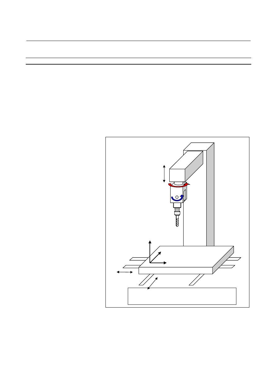
In a 5-axis machine having two tool rotation axes as shown in Fig.
22.5.1 (a), this function can perform cutter compensation.
Shown below is a 5-axis machine that has tool rotation axis B on the
Y-axis and tool rotation axis C on the Z-axis.
This machine configuration is used as a sample configuration in the
following explanation unless otherwise noted.
Cutter compensation in tool rotation machines is classified into two
types according to the way of machining: tool side offset and
leading edge offset.
Workpiece coordinate system: A coordinate
system used for creating programs
B
C
Z
Y
X
X
Y
Z Workpiece coordinate
system
Fig. 22.5.1 (a) Machine having two tool rotation axes