FANUC Series 30i/300i/300is-MODEL A. Machining Center System. User's manual - page 116
 

  Index      Manuals     FANUC Series 30i/300i/300is-MODEL A. Machining Center System. User's manual (B-63944EN/03)


Search            copyright infringement  


Content      ..     114      115      116      117     ..


FANUC Series 30i/300i/300is-MODEL A. Machining Center System. User's manual - page 116


22.5-AXIS MACHINING FUNCTION

 PROGRAMMING 

B-63944EN/03


- 884 - 

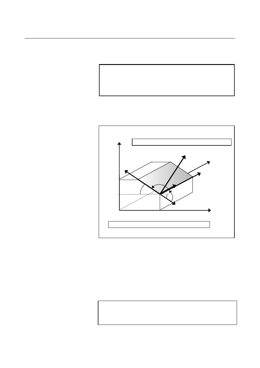
G68.2 P4 X200.0 Y0 Z50.0 I30.0 J0 K90.0 ; 
G53.1 ; 
    : 

By the third command angle 

γ

, the X-axis and Y-axis of the feature 

coordinate system are determined. 
 

NOTE 

When vector A and vector B are considered to be 
parallel with each other (when the angle formed by 
the two vectors is smaller than 1

°

), alarm PS5457 

is issued. 


Example 

The example of a program when feature coordinate system like the 
figure below is used is shown below. 


Origin of a feature coordinate system : 


(200.0, 0, 50.0) 


Angle by which the X-axis vector is rotated about the Y-axis of 
the workpiece coordinate system : 30 degrees 


Angle by which the Y-axis vector is rotated about the X-axis of 
the workpiece coordinate system : 0 degree 

  Angle of rotation about the Z-axis of the feature coordinate 

system : 90 degrees 

 
Example of a program 


X

Z

30

°

Xc 

Zc 

Yc

Workpiece coordinate system X-Y-Z 

Feature coordinate system Xc-Yc-Zc

200.0

50.0

A

B

B-63944EN/03

 PROGRAMMING 

22.5-AXIS MACHINING FUNCTION


- 885 - 

22.3.3.5 

Absolute multiple command 

 
By additionally specifying G68.2 in the tilted working plane 
command mode, a feature coordinate system produced by additionally 
applying coordinate system conversion to the workpiece coordinate 
system can be set.    The workpiece coordinate system is resumed by 
specifying G69. 
This function is enabled by setting bit 0 (MTW) of parameter No. 
11221. 
 

Format 

The format of the tilted working plane command (G68.2) is 
applicable. 
Specify the origin of a feature coordinate system in the workpiece 
coordinate system. 
 

NOTE 


Before specifying G68.2, cancel tool length 
compensation and tool radius compensation.    If 
G68.2 is specified during tool length compensation 
or tool radius compensation, alarm PS5462 is 
issued. 


22.5-AXIS MACHINING FUNCTION

 PROGRAMMING 

B-63944EN/03


- 886 - 

Example of operation 

An example of operation on a tool rotation type machine is explained 
below. 
The machine configuration is "BC type with the reference tool axis 
being the Z-axis". 


B:  2nd rotation axis (slave)

C:    1st rotation axis (master)


Control point 

Tool holder offset value 
  = Parameter No. 19666 

Tool length offset = H01


Machine on which tool rotary 

axes cross each other 

Tool center point


Sample program 2 
O0100 ; 
N1 G55 ; 
N2 G90 G01 X20.0 Y5.0 Z0 F1000 ; 
N3 G68.2 X20.0 Y5.0 Z0 I0 J90.0 K0 ; 
N4 G53.1 ; 
 : 
N5 X-15.0 Y0 Z-15.0 ; 
N6 G68.2 X5.0 Y20.0 Z0 I90.0 J90.0 K0 ; 
N7 G53.1; 
 : 
N8 G69 ; 
 : 
 

B-63944EN/03

 PROGRAMMING 

22.5-AXIS MACHINING FUNCTION


- 887 - 


N6 command

Y

Z

N4 command

Machine operation by sample program 1 

N7 command

N5 command

Y

Z

Y

Z

Xc 

Yc

Zc 

Y

Z

Feature coordinate system 
Xc-Yc-Zc 

Feature coordinate system 
Xc-Yc-Zc 

Xc

Yc 

Zc 

Xc

Yc 

Zc 

Xc 

Yc 

Zc 

G55

Machine 
origin 


N4 block: Rotates the tool in the Z-axis direction in the feature 

coordinate system. 

N5 block:  Specifies coordinates in the feature coordinate system. 
N6 block:  Sets a new feature coordinate system. 
N7 block:  Rotates the tool in the Z-axis direction in the new feature 

coordinate system. 


22.5-AXIS MACHINING FUNCTION

 PROGRAMMING 

B-63944EN/03


- 888 - 

22.3.3.6 

Incremental multiple command 

 
By specifying G68.4, coordinate system conversion can be applied to 
the currently set feature coordinate system. 
This function is enabled by setting bit 0 (MTW) of parameter No. 
11221. 
 

Format 

The format of the tilted working plane command (G68.2) is 

applicable. 

Specify the origin of a feature coordinate system in the immediately 
preceding feature coordinate system. 


Specification method 

Incremental multiple command 

Eulerian angle 

G68.4 

Roll-pitch-yaw G68.4 

P1 

Three points 

G68.4 P2 

Two vectors 

G68.4 P3 

Projection angles 

G68.4 P4 


NOTE 

1  Before specifying G68.4, cancel tool length 

compensation and tool radius compensation.    If 
G68.4 is specified during tool length compensation 
or tool radius compensation, alarm PS5462 is 
issued.  

2  Do not specify G68.4 during workpiece setting 

error compensation.    Otherwise, alarm PS0437 is 
issued.  


B-63944EN/03

 PROGRAMMING 

22.5-AXIS MACHINING FUNCTION


- 889 - 

Example of operation 

An example of operation on a tool rotation type machine is explained 
below. 
Rotary axis C rotates about the Z-axis (master axis). 
Rotary axis B rotates about the Y-axis (slave axis). 


B:  2nd rotation axis (slave)

C:    1st rotation axis (master)


Control point 

Tool holder offset value 
  = Parameter No. 19666 

Tool length offset = H01


BC type tool axis Z-axis


(Axes are intersecting.) 

Tool center point


Sample program 3 
O0200 ; 
N1 G55 ; 
N2 G90 G01 X20.0 Y5.0 Z0 F1000 ; 
N3 G68.2 X20.0 Y5.0 Z0 I0 J90.0 K0 ; 
N4 G53.1 ; 
 : 
N5 X-15.0 Y0 Z-15.0 ; 
N6 G68.4 X-15.0 Y0 Z-15.0 I90.0 J90.0 K-90.0 ; 
N7 G53.1; 
 : 
N8 G69 ; 
 : 
 

22.5-AXIS MACHINING FUNCTION

 PROGRAMMING 

B-63944EN/03


- 890 - 


N6 command

Y

Z

N4 command

Machine operation by sample program 2 

N7 command

N5 command

Xc1

Yc1 

Zc1 

Y

Z

Y

Z

Xc2 

Yc2

Zc2 

Y

Z

Feature coordinate system 
Xc1-Yc1-Zc1 

Feature coordinate system 
Xc2-Yc2-Zc2 

Xc1

Yc1 

Zc1 

Xc2 

Yc2 

Zc2 

Xc1 

Yc1 

Zc1 

Xc1 

Yc1 

Zc1 


N4 block: Rotates the tool in the Z-axis direction in the feature 

coordinate system. 

N5 block:  Specifies coordinates in the feature coordinate system. 
N6 block: Applies coordinate system conversion to the feature 

coordinate system based on Eulerian angle to set a new 
feature coordinate system. 

N7 block:  Rotates the tool in the Z-axis direction in the new feature 

coordinate system. 


B-63944EN/03

 PROGRAMMING 

22.5-AXIS MACHINING FUNCTION


- 891 - 

Limitation 
 - Basic restrictions 

The restrictions for this function are similar to those for the 
three-dimensional coordinate system conversion function. 
 

 - Increment system 

The same increment system must be used for the basic three axes used 
by this function. 
 

  - Rapid traverse command 

The rapid traverse command must specify linear rapid traverse (Bit 1 
(LRP) of parameter No.1401= 1). 
 

  - Feature coordinate system and three-dimensional coordinate system conversion 

An alarm occurs if an attempt is made to set a feature coordinate 
system in another feature coordinate system. 
An alarm also occurs if an attempt is made to set a new coordinate 
system by performing three-dimensional coordinate system 
conversion in a feature coordinate system. 
 

  - Positioning in the machine coordinate system 

Positioning commands in the machine coordinate system, such as G28, 
G30, and G53, operate in the machine coordinate system rather than in 
the feature coordinate system. 
 

  - External mirror image 

If an attempt is made to use this function and the external mirror 
image function simultaneously, this function takes effect before the 
external mirror image function. 
 

Actual path

Y

X

Yc

Xc

Programmed path

Feature coordinate
system

Workpiece coordinate
system

Mirrored position


Content      ..     114      115      116      117     ..