FANUC Series 30i/300i/300is-MODEL A. Machining Center System. User's manual - page 109
 

  Index      Manuals     FANUC Series 30i/300i/300is-MODEL A. Machining Center System. User's manual (B-63944EN/03)


Search            copyright infringement  


Content      ..     107      108      109      110     ..


FANUC Series 30i/300i/300is-MODEL A. Machining Center System. User's manual - page 109


22.5-AXIS MACHINING FUNCTION

 PROGRAMMING 

B-63944EN/03


- 828 - 

22.2 

TOOL POSTURE CONTROL 


Overview 

Under tool center point control, the tool tip moves along a specified 
path even when the tool direction relative to the workpiece changes.   
Usually, however, the two rotary axes are controlled independently of 
each other, and the posture of the tool is not controlled. 
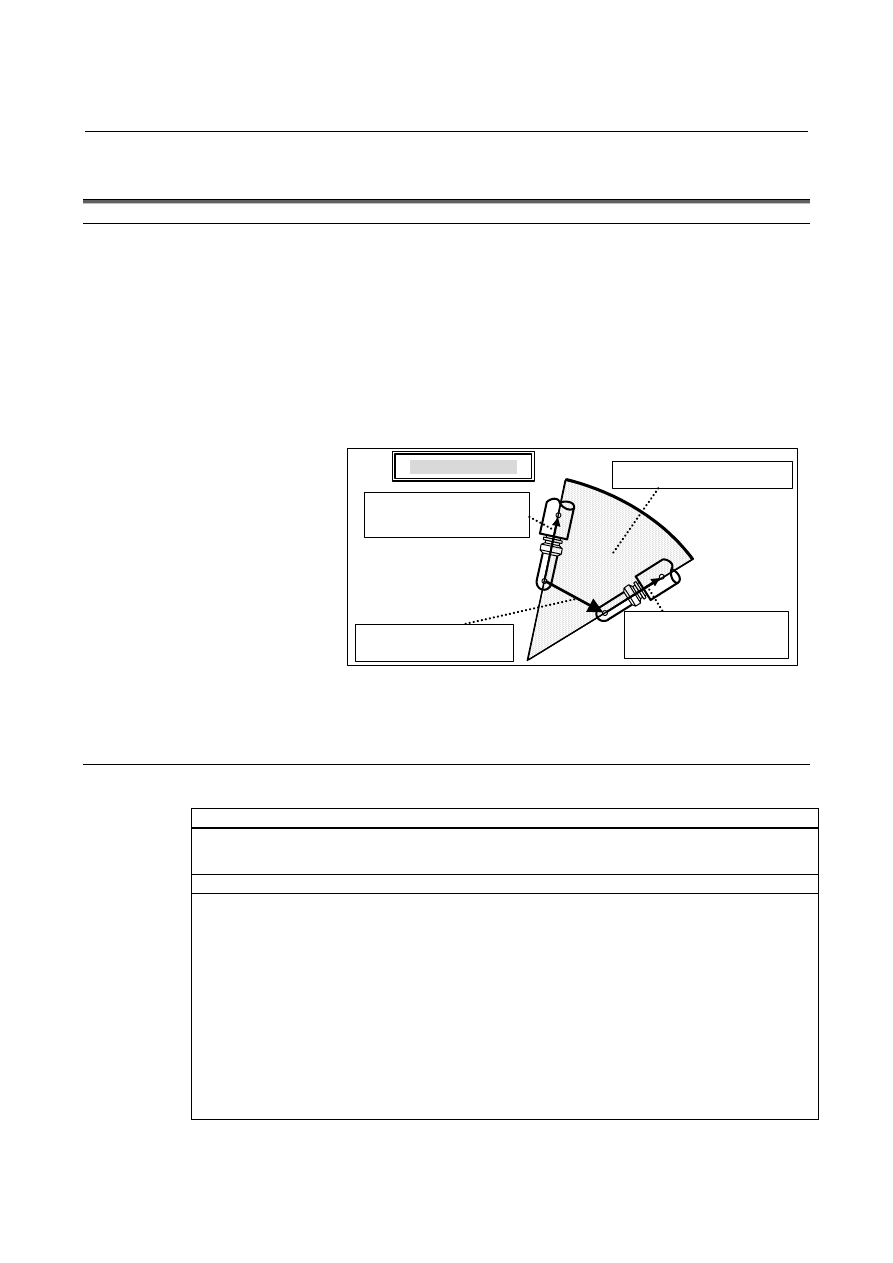
Under tool posture control, the tool posture is controlled every 
moment for operation on the plane formed by the tool postures (tool 
length compensation vectors) at the start point and end point of a 
block. 
This control method is suitable for machining a plane with the side of 
a tool by using tool center point control. 

Tool posture control

Plane formed by Vs and Ve

Tool length compensation 

vector Vs at block start point

Tool length compensation 

vector Ve at block end point

Programmed path 


Fig. 22.2 (a)    Tool posture control 

 
This function is optional.    The tool center point control option is also 
needed. 
 

Format 


Format


G43.4 

IP

α

β

_ H_ P_ ;  Tool center point control (type 1) 

G43.5 

IP

_ H_ Q_ P_ ; 

Tool center point control (type 2) 

Description of symbols 

IP

  : For an absolute command, the coordinates of travel end point of the tool 

center point 


  For an incremental command, the travel distance of the tool center point 

α

β

 : For an absolute command, the coordinates of the end point of the rotation axis


  For an incremental command, the travel distance of the rotation axis 

H  : Tool offset number 
Q  : Tool tilted angle (degree) 
P  : Tool posture control disabled (P0) or tool posture control enabled (P1)   

However, bit 0 (TPC) of setting parameter No. 19604 can be used to select 
the behavior taken when the address P command is not present. 


B-63944EN/03

 PROGRAMMING 

22.5-AXIS MACHINING FUNCTION


- 829 - 

Tool posture control is enabled when P1 is specified or disabled when 
P0 is specified in the G43.4 and G43.5 blocks.    The behavior taken 
when the address P command is not present can be selected by bit 0 
(TPC) of parameter No. 19604.    The setting of tool posture control 
selected in the G43.4 and G43.5 blocks is kept until the tool center 
point control cancellation command (G49) is specified. 
 
Example: 

O0010 
… 
N10 G90 G00 X30.0 Y-30.0 Z0.0; 
N20 G43.5 H1 P1; 
N30 G42.6 D2; 
N40 G01 X20.0 Y-20.0 I-1 J1 K2 F_;
N50 Y20.0 I-1 J-1 K2; 
N60 X-20.0 I1 J-1 K2; 
N70 Y-20.0 I1 J1 K2; 
N80 X20.0 I-1 J1 K2; 
… 
G40; 
G49; 
M30; 


Y

Z

In N20 to N80 in program O0010 to the 
left, the sides of a quadrangular pyramid 
trapezoid as shown below can be 
machined by the side of the tool using 
tool posture control.    The following figure 
illustrates tool movement by N50.    The 
command in N30 is the three-dimensional
cutter compensation command. 


Fig. 22.2 (b)    Example of tool posture control 


Explanation 

In tool posture control, the two rotation axes are controlled so that the 
momentary tool posture (tool length compensation vector) satisfies the 
following conditions (Fig. 22.2 (c)). 
The momentary tool posture (tool length compensation vector) is 

present on the plane configured by the tool length compensation 
vector at the block start point and that at the block end point. 

The angle which the tool length compensation vector at the block start 

point makes with the momentary tool length compensation vector 
is the angle obtained by proportionally dividing the angle which 
the tool length compensation vector at the block start point makes 
with the tool length compensation vector at the block end point. 

 
Tool posture control is enabled when P1 is specified or disabled when 
P0 is specified in the tool center point control start command 
(G43.4/G43.5) blocks.  Bit 0 (TPC) of setting parameter No. 19604 
can be used to select whether tool posture control is enabled or 
disabled when the address P command is not present.    The setting of 
tool posture control selected in the G43.4 and G43.5 blocks is kept 
until the tool center point control cancellation command (G49) is 
specified. 
 
This function can be used for positioning (G00) and linear 
interpolation (G01) during tool center point control. 
 
Other notes and restrictions are the same as those for tool center point 
control. 
 

22.5-AXIS MACHINING FUNCTION

 PROGRAMMING 

B-63944EN/03


- 830 - 


Program specification path 

Control 
point 

Tool center 
point 

Block start point 

Block end point 

Vs

Ve

θ

Θ

Vs

Ve

Plane configured by tool length compensation vectors Vs and Ve 
  Momentary tool length compensation vector V is controlled so as to 
be present on the plane. 

=

θ


Θ


Control is made so that angle 

θ

 which Vs makes with V 

satisfies this expression. 


Fig. 22.2 (c) Tool posture control 


B-63944EN/03

 PROGRAMMING 

22.5-AXIS MACHINING FUNCTION


- 831 - 

Singular point 
  - "Tool-side rotary axis" and "workpiece-side rotary axis" 

When tool center point control type 2 is specified, programming needs 
to be performed considering a singular point and singular point 
posture.    The "tool-side rotary axis" and "workpiece-side rotary axis" 
used in the descriptions of a singular point and singular point posture 
later are explained below. 
On a 5-axis machine that has two rotary axes, one rotary axis has a 
function for tilting the tool toward a workpiece.    This rotary axis is 
referred to as a "tool-side rotary axis". 
The other rotary axis is referred to as a "workpiece-side rotary axis". 
The table below indicates the axes that represent these rotary axes for 
each mechanical unit type. 
 

Table 22.2 (a)    "Tool-side rotary axis" and "workpiece-side rotary axis" 

Mechanical unit type 

(parameter No. 19680)

Tool-side rotary axis 

Workpiece-side rotary 

axis 

Tool rotation type (2) 

Slave axis 

Master axis 

Table rotation type (12)

Master axis 

Slave axis 

Composite type (21) 

Tool rotary axis 

Table rotary axis 


Tool rotation type 

Table rotation type

Composite type

Tool-side rotary axis

Workpiece-side rotary axis 


Fig. 22.2 (d)    "Tool-side rotary axis" and "workpiece-side rotary axis" 


  - Singular point, singular point posture 

A tool posture is uniquely determined when the angular displacements 
of the two rotary axes are determined.  However, a combination of 
the angular displacements of the two rotary axes for determining a 
particular tool posture is not uniquely determined usually. 
In particular, a tool posture with the angular displacement of the 
workpiece-side rotary axis being arbitrary is referred to as a "singular 
point posture", and the angular displacement of the tool-side rotary 
axis that causes the tool posture to assume a singular point posture is 
referred to as the "singular point (or singular point angular 
displacement)".  When the angular displacement of the tool-side 
rotary axis is at a singular point, the center of the workpiece-side 

22.5-AXIS MACHINING FUNCTION

 PROGRAMMING 

B-63944EN/03


- 832 - 

rotary axis and the tool posture (tool orientation) are parallel with each 
other. 
Example) 
 

Suppose that a tool rotation type machine is used, the master axis 
is the C-axis (about the Z-axis), the slave axis is the B-axis 
(about the Y-axis), and the reference tool axis direction is the 
Z-axis direction.    In this case, singular point B = ..., 0

°

, 180

°

, ..., 

and a singular point posture (the same direction as the Z-axis 
direction or the direction opposite to the Z-axis direction) results 
at an arbitrary C-axis angular displacement. 

For example, when the B-axis angular displacement is B = 0 (singular 
point) as shown in Fig. 22.2 (e), the same tool posture (singular point 
posture) is assumed at an arbitrary C-axis angular displacement. 


C=0

C=60

B=0 

(Singular point)

X

Z

Singular point 

posture 

B=0 

(Singular point)


Fig. 22.2 (e)    Singular point and singular point posture 

 
There is no singular point and singular point posture on some types of 
machines as in the case where the reference tool axis direction is tilted 
(parameter No. 19698 and No. 19699) or a rotary axis is an angular 
axis (parameter No. 19682, No. 19683, No. 19687, and No. 19688). 


B-63944EN/03

 PROGRAMMING 

22.5-AXIS MACHINING FUNCTION


- 833 - 

  - When the tool posture is close to a singular point posture 

When tool posture control is exercised on a machine that has a 
singular point, and the tool posture becomes close to a singular point 
posture during execution of a block, the operation of the 
workpiece-side rotary axis can become so large, resulting in unstable 
machine operation. 
In such a case, machine operation can be made stabler, the machining 
time can be reduced, and the surface roughness can be improved by 
changing the tool posture at the block end point so that the tool 
posture passes through a singular point posture. 

A large and abrupt movement is made on
the workpiece-side rotary axis when the tool
posture passes through a singular point

close posture. 

A large and abrupt movement on the workpiece-side 
rotary axis can be avoided by passing through a 
singular point posture.  By passing through a 
singular point posture, the tool posture at the block

end is changed within the allowable range. 


Fig. 22.2 (f)    Changing the tool posture at a block end point 

 
When tool posture control is used, and the angle between a tool 
posture and singular point posture is equal to or less than the value of 
(parameter No. 19738), the tool posture is determined to be close to a 
singular point posture.    The tool posture at this time is referred to as a 
"singular point close posture".  When tool center point control is 
specified (G43.5) based on type 2, which specifies the tool posture at 
the block end point with tool axis direction (I, J, K), each block is 
checked to see if a singular point close posture is assumed.  If a 
singular point close posture is assumed in a block, the tool posture at 
the end point of the block is changed (the rotary axis angular 
displacement is changed) to pass through a singular point posture.    If 
the end points before and after the workpiece-side rotary axis is 
changed vary largely from each other as the result of changing the tool 
posture at the block end point, the change in the tool posture at the 
block end point can be suppressed. 
However, if the value of parameter No. 19738 is 0, the tool posture at 
the block end point is not changed. 
If the tool posture at the start point or end point of a block is a singular 
point posture or the tool posture becomes a singular point posture in 
the middle of a block, the tool posture is not changed at the block end 
point. 

22.5-AXIS MACHINING FUNCTION

 PROGRAMMING 

B-63944EN/03


- 834 - 

If this angle is equal to or 
less than the value of 
parameter No. 19738, a 
singular point close 
posture is assumed. 

Tool posture 

Singular 
point posture


Fig. 22.2 (g)    Singular point close posture 

 
If a singular point close posture is assumed during execution of a 
block, change the angular displacements of the rotary axes at the end 
point of the block calculated from the tool posture specified by (I, J, 
K) so that the tool posture passes through a singular point posture in 
the block as indicated below. 
Tool-side rotary axis: 
 

Turned reversely relative to the singular point angular 
displacement 
Example:  
 

When the end point angular displacement before a change is 
60

°

, and the singular point angular displacement is 20

°

, the 

end point angular displacement after a change is -20

°

Workpiece-side rotary axis: 
 

Same as the angular displacement at the start point 
Example: 
 

When the end point angular displacement after a change is 
30

°

, and the start point angular displacement is -150

°

, the 

end point angular displacement after a change is -150

°

However, if both of the difference between the end point angular 
displacement before a change and (end point angular displacement 
after a change + 180

°

) and the difference between the end point 

angular displacement before a change and (end point angular 
displacement after a change - 180

°

) are equal to or greater than the 

value of parameter No. 19739, the program is executed according to 
the setting of bit 3 (NPC) of parameter No. 19696, suppressing the 
change, or alarm PS5421 is issued. 
This function is used to avoid unstable machine operation in a block 
where a singular point close posture is assumed as shown in Fig. 22.2 
(f). 
 

B-63944EN/03

 PROGRAMMING 

22.5-AXIS MACHINING FUNCTION


- 835 - 

Notes 
  - When the reference tool axis or a rotary axis is inclined 

When tool center point control is used, the inclination of the reference 
tool axis can be set in parameter No. 19698 and No. 19699, and the 
inclination of a rotary axis can be set in parameter No. 19682, No. 
19683, No. 19687 and No. 19688. 
On a machine with the reference tool axis or a rotary axis being 
inclined, all tool postures cannot be assumed.  Some tool postures 
can never be assumed by setting the angular displacements of the two 
rotary axes in any way.  If the tool posture passes through any of 
those impossible tool postures during program execution when tool 
posture control is enabled, alarm PS0432 is issued before execution of 
the block. 
Example: 
 

On a tool rotation type machine where the master axis is the 
C-axis (about the Z-axis), the slave axis is the B-axis (about the 
Y-axis), and the reference tool axis direction is inclined relative 
to the positive Z-axis direction (a non-zero value is set in 
parameter No. 19698 and No. 19699), no tool posture can be 
assumed in the positive or negative direction of the Z-axis.    So, 
if a block specifies such a tool posture during tool posture control, 
alarm PS0432 is issued before execution of the block. 


O0010 
… 
G43.5 H1 P1; 
… 
N10 X_ Y_ Z_ I1 J0 K2;
N20 X_ Y_ Z_ I-1 J0 K2;
… 
G49; 
M30; 

I1 J0 K2;

Positive Z-axis direction   

I-1 J0 K2;


Y

Z

If O0010 is executed on the machine in 
the example above, the tool posture 
assumes the positive Z-axis direction 
during N20, so alarm PS0432 is issued 
before execution of N20. 


Fig. 22.2 (h)    Example of impossible tool posture 


Content      ..     107      108      109      110     ..