FANUC Series 30i/300i/300is-MODEL A. Machining Center System. User's manual - page 54
 

  Index      Manuals     FANUC Series 30i/300i/300is-MODEL A. Machining Center System. User's manual (B-63944EN/03)


Search            copyright infringement  


Content      ..     52      53      54      55     ..


FANUC Series 30i/300i/300is-MODEL A. Machining Center System. User's manual - page 54


15.COMPENSATION FUNCTION

 PROGRAMMING 

B-63944EN/03


- 388 - 

Example 

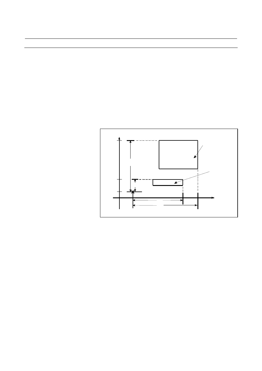
Sample program of a scaling in each axis 
 
 O1; 
 

G51 X20.0 Y10.0 I750 J250; (

×

 0.75 in the X direction, 

×

 0.25 in 

the Y direction) 


G00 G90 X60.0 Y50.0; 


G01 X120.0 F100; 

 G01 

Y90; 

 G01 

X60; 

 G01 

Y50; 

 G50; 
 M30; 
 

Y axis

X axis

100

75

Programmed figure

Scaled figure

Scaling center

80

20

90

10

20

95

120

30

(60,50)


Fig. 15.2 (g)    Program example of scaling in each axis   


B-63944EN/03

 PROGRAMMING 

15.COMPENSATION FUNCTION


- 389 - 

15.3 

PROGRAMMABLE MIRROR IMAGE (G50.1, G51.1) 

 
A mirror image of a programmed command can be produced with 
respect to a programmed axis of symmetry (Fig. 15.3 (a)). 
 

Y

100

60

50

50

X

60

100

(1)

(2)

(3)

(4)

(1) Original image of a programmed command
(2) Image symmetrical about a line parallel to the Y-axis and crossing the

X-axis at 50

(3) Image symmetrical about point (50, 50)
(4) Image symmetrical about a line parallel to the X-axis and crossing the

Y-axis at 50

Axis of symmetry (X=50)

Axis of symmetry
(Y=50)

40

0

40

0


Fig. 15.3 (a)    Programmable mirror image 


Format 

G51.1 

IP

_ ; 

Setting a programmable image


 : 

A mirror image of a command specified in 

 : 

these blocks is produced with respect to 


 : 

the axis of symmetry specified by G51.1 


 : 

IP

_;.


G50.1 

IP

_ ;   

Canceling a programmable mirror image


IP

_ :  Point (position) and axis of symmetry for producing a 

mirror image when specified with G51.1. 


Axis of symmetry for producing a mirror image when 
specified with G50.1. Point of symmetry is not 
specified. 

15.COMPENSATION FUNCTION

 PROGRAMMING 

B-63944EN/03


- 390 - 

Explanation 
  - Mirror image by setting 

If the programmable mirror image function is specified when the 
command for producing a mirror image is also selected by a CNC 
external switch or CNC setting (see III-4.5), the programmable mirror 
image function is executed first. 
 

  - Mirror image on a single axis in a specified plane 

Applying a mirror image to one of the axes on a specified plane 
changes the following commands as follows : 
 

Command Explanation 

Circular command 

G02 and G03 are interchanged. 

Tool radius 

 tool nose radius 

compensation 

G41 and G42 are interchanged. 

Coordinate system rotation 

CW and CCW (directions of rotation) 

are interchanged. 


Limitation 
  - Scaling and coordinate system rotation 

Processing proceeds from program mirror image to scaling and 
coordinate system rotation in the stated order. The commands should 
be specified in this order, and, for cancellation, in the reverse order. 
Do not specify G50.1 or G51.1 during scaling or coordinate system 
rotation mode. 
 

  - Commands related to reference position return and coordinate system 

In programmable mirror image mode, G codes related to reference 
position return (G27, G28, G29, G30, etc.) and those for changing the 
coordinate system (G52 to G59, G92, etc.) must not be specified. If 
any of these G codes is necessary, specify it only after canceling the 
programmable mirror image mode. 
 

B-63944EN/03

 PROGRAMMING 

15.COMPENSATION FUNCTION


- 391 - 

15.4 

NORMAL DIRECTION CONTROL (G40.1,G41.1,G42.1) 


Overview 

When a tool with a rotation axis (C-axis) is moved in the XY plane 
during cutting, the normal direction control function can control the 
tool so that the C-axis is always perpendicular to the tool path (Fig. 
15.4 (a)).   
 

Tool 

Tool

Programmed tool path 

Normal direction (in 
which the tool moves) 

C-axis

C-axis


Fig. 15.4 (a) Sample Movement of the tool 


Format 

G41.1 ;   Normal direction control, left 
G42.1 ;  Normal direction control, right 
G40.1 ;  Cancel normal direction control 

The normal direction control, left (G41.1) command is 
used when the workpiece is on the right side of the tool as 
viewed while you are looking into the tool’s way. 
Once either G41.1 or G42.1 is issued, normal direction 
control is enabled (normal direction control mode). 
Issuing G40.1 cancels the normal direction control mode. 


15.COMPENSATION FUNCTION

 PROGRAMMING 

B-63944EN/03


- 392 - 


Center of the arc 

Programmed tool path 

Tool center path 

Tool center path 

Programmed tool path 


Fig. 15.4 (b)    Normal direction control, left (G41.1)  Fig. 15.4 (c)    Normal direction control, right (G42.1) 


Explanation 
  - Angle of the C axis 

When viewed from the center of rotation around the C-axis, the 
angular displacement about the C-axis is determined as shown in Fig. 
15.4 (d). The positive side of the X-axis is assumed to be 0, the 
positive side of the Y-axis is 90

°

, the negative side of the X-axis is 

180

°

, and the negative side of the Y-axis is 270

°

Center of rotation 

+Y

180

°

+X 

270

°

0

°


90

°


Fig. 15.4 (d) Angle of the C axis 


  - Normal direction control of the C axis 

When the cancel mode is switched to the normal direction control 
mode, the C-axis becomes perpendicular to the tool path at the 
beginning of the block containing G41.1 or G42.1. 
In the interface between blocks in the normal direction control mode, 
a command to move the tool is automatically inserted so that the 
C-axis becomes perpendicular to the tool path at the beginning of each 
block. The tool is first oriented so that the C-axis becomes 
perpendicular to the tool path specified by the move command, then it 
is moved along the X- and Y axes. 
In the cutter compensation mode, the tool is oriented so that the C-axis 
becomes perpendicular to the tool path created after compensation. 

B-63944EN/03

 PROGRAMMING 

15.COMPENSATION FUNCTION


- 393 - 

In single-block operation, the tool is not stopped between a command 
for rotation of the tool and a command for movement along the X- and 
Y-axes. A single-block stop always occurs after the tool is moved 
along the X- and Y-axes. 
 

S

N1

N2

S

N3

S

Programmed tool path

S : Single block stop point

Tool center path 


Fig. 15.4 (e) Point at which a single-block stop occurs in the normal 

direction control mode 

 
Before circular interpolation is started, the C-axis is rotated so that the 
C-axis becomes normal to the arc at the start point. During circular 
interpolation, the tool is controlled so that the C-axis is always 
perpendicular to the tool path determined by circular interpolation. 

Center of the arc 

Programmed tool path 

Tool center path

The tool is controlled so that the C-axis 
is always normal to the tool path 
determined by circular interpolation. 

A rotation command is inserted so 
that the C-axis becomes normal to 
the arc at the start point. 


Fig. 15.4 (f) Normal direction control of the circular interpolation 


NOTE 


During normal direction control, the C axis always 
rotates through an angle less than 180 deg. I.e., it 
rotates in whichever direction provides the shorter 
route. 


15.COMPENSATION FUNCTION

 PROGRAMMING 

B-63944EN/03


- 394 - 

  - C axis feedrate 

Movement of the tool inserted at the beginning of each block is 
executed at the feedrate set in parameter 5481. If dry run mode is on at 
that time, the dry run feedrate is applied. If the tool is to be moved 
along the X-and Y-axes in rapid traverse (G00) mode, the rapid 
traverse feedrate is applied. 
The feedrate of the C axis during circular interpolation is defined by 
the following formula. 

Amount of movement of the C axis (deg) 

×


Length of arc (mm or inch) 

(deg/min) 

 
F :  Feedrate (mm/min or inch/min) specified by the corresponding 

block of the arc 

Amount of movement of the C axis : 
 

The difference in angles at the beginning and the end of the 
block. 


NOTE 


If the feedrate of the C axis exceeds the maximum 
cutting speed of the C axis specified to parameter 
No. 1430, the feedrate of each of the other axes is 
clamped to keep the feedrate of the C axis below 
the maximum cutting speed of the C axis. 


  - Normal direction control axis 

A C-axis to which normal-direction control is applied can be assigned 
to any axis with parameter No. 5480. 
 

  - Angle for which figure insertion is ignored 

When the rotation angle to be inserted, calculated by normal-direction 
control, is smaller than the value set with parameter No. 5482, the 
corresponding rotation block is not inserted for the axis to which 
normal-direction control is applied. This ignored rotation angle is 
added to the next rotation angle to be inserted, the total angle being 
subject to the same check at the next block. 
If an angle of 360 degrees or more is specified, the corresponding 
rotation block is not inserted. 
If an angle of 180 degrees or more is specified in a block other than 
that for circular interpolation with a C-axis rotation angle of 180 
degrees or more, the corresponding rotation block is not inserted. 
 

B-63944EN/03

 PROGRAMMING 

15.COMPENSATION FUNCTION


- 395 - 

  - Movement for which arc insertion is ignored 

Specify the maximum distance for which machining is performed with 
the same normal direction as that of the preceding block. 

 Linear 

movement 


When distance N2, shown below, is smaller than the set value, 
machining for block N2 is performed using the same direction as 
that for block N1. 

N1

N2

N

Tool center path

Distance

Programmed tool path


 Circular 

movement 


When the diameter of block N2, shown below, is smaller than the 
set value, machining for block N2 is performed using the same 
normal direction as that for block N1. And control as 
compensation along the circular arc is not performed. 


N1

N2

N3 

Tool center path 

Programmed tool path

Diameter


NOTE 

1  Do not specify any command to the C axis during 

normal direction control. Any command specified at 
this time is ignored. 

2  Before processing starts, it is necessary to 

correlate the workpiece coordinate of the C axis 
with the actual position of the C axis on the 
machine using the coordinate system setting (G92) 
or the like. 

3  The helical cutting option is required to use this 

function. Helical cutting cannot be specified in the 
normal direction control mode. 

4  Normal direction control cannot be performed by 

the G53 move command. 

5  The C-axis must be a rotation axis. 


Content      ..     52      53      54      55     ..