FANUC Series 30i/300i/300is-MODEL A. Machining Center System. User's manual - page 22
 

  Index      Manuals     FANUC Series 30i/300i/300is-MODEL A. Machining Center System. User's manual (B-63944EN/03)


Search            copyright infringement  


Content      ..     20      21      22      23     ..


FANUC Series 30i/300i/300is-MODEL A. Machining Center System. User's manual - page 22


4.INTERPOLATION FUNCTIONS

 PROGRAMMING 

B-63944EN/03


- 132 - 

Limitation 
 - Manual operation 

The hypothetical axis can be used only in automatic operation. In 
manual operation, it is not used, and movement takes place.     
 

 - Move command 

Specify hypothetical axis interpolation only in the incremental mode.   
 

 - Coordinate rotation 

Hypothetical axis interpolation does not support coordinate rotation. 
 

Example 
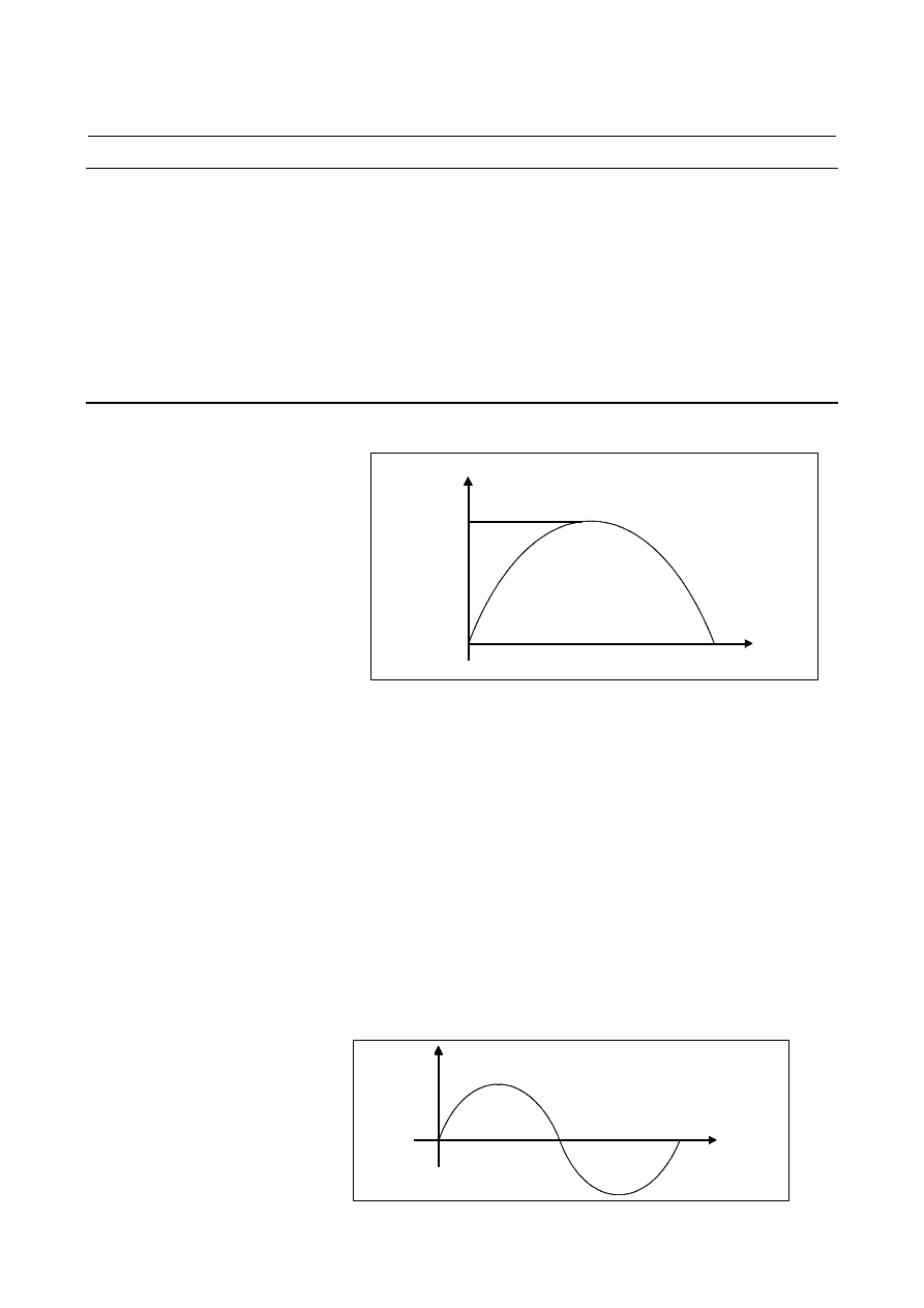
 - Sine interpolation 

Y

Z

20.0

0

10.0


N001  G07  X0  ; 
N002  G91  G17  G03  X-20.0  Y0.0  I-10.0  Z20.0  F100 ; 
N003  G01  X10.0 ; 
N004  G07  X1 ;  
From the N002 to N003 blocks, the X-axis is set to a hypothetical axis. 
The N002 block specifies helical cutting in which the Z-axis is the 
linear axis. Since no movement takes place along the X axis, 
movement along the Y-axis is performed while performing sine 
interpolation along the Z-axis. 
In the N003 block, there is no movement along the X-axis, and so the 
machine dwells until interpolation terminates. 
 

  - Changing the feedrate to form a sine curve 

(Sample program) 
G07Z0 ;       

The Z-axis is set to a hypothetical axis. 

G02X0Z0I10.0F4. ;  The feedrate on the X-axis changes sinusoidally.   
G07Z1 ;  

  The use of the Z-axis as a hypothetical axis is 

canceled.  

F

4.0

Xt


B-63944EN/03

 PROGRAMMING 

4.INTERPOLATION FUNCTIONS


- 133 - 

4.16 

VARIABLE LEAD THREADING (G34) 

 
Specifying an increment or a decrement value for a lead per screw 
revolution enables variable lead threading to be performed. 


Fig. 4.16 (a)    Variable lead screw 


Format 

G34 

IP

_ F_ K_ Q_ ; 

IP

_ : End point 

F_  : Lead in longitudinal axis direction at the start point 
K_  : Increment and decrement of lead per spindle revolution
Q_  : Shift amount of starting angle of thread cutting


Explanation 

Address other than K are the same as in straight/taper thread cutting 
with G32. 
The K value depends on the increment system of the reference axis, as 
indicated in Table 4.16 (a). 
If the specified K value exceeds the range indicated in Table 4.16 (a), 
if the maximum lead is exceeded after a change due to the K value, or 
if the lead value is negative, an alarm PS0313 will be issued. 
 

Table 4.16 (a)    Range of valid K values 

Increment system 

of reference axis

Metric input (mm/rev) 

Inch input (inch/rev) 

IS-A  


±

0.001 to 

±

500.000  

±

0.00001 to 

±

50.00000 

IS-B  

±

0.0001 to 

±

500.0000  

±

0.000001 to 

±

50.000000 

IS-C  

±

0.00001 to 

±

50.00000  

±

0.0000001 to 

±

5.0000000 

IS-D  

±

0.000001 to 

±

5.000000  

±

0.00000001 to 

±

0.50000000

IS-E  

±

0.0000001 to 

±

0.5000000  

±

0.000000001 to 

±

0.050000000


 CAUTION 


The "thread cutting cycle retract" is not effective for 
G34. 


Example 

Lead at the start point: 8.0 mm 
Lead increment: 0.3 mm/rev 
 

G34 Z-72.0 F8.0 K0.3 ; 

4.INTERPOLATION FUNCTIONS

 PROGRAMMING 

B-63944EN/03


- 134 - 

4.17 

CIRCULAR THREADING (G35, G36) 

 
Using the G35 and G36 commands, a circular thread, having the 
specified lead in the direction of the major axis, can be machined. 
 

L

L:  Lead


Fig. 4.17 (a)    Circular threading 


Format 

A sample format for the G18 plane (Z-X plane) is indicated below.  
When using the format for the G17 plane (X-Y plane), change the 
addresses Z, X, K, and I to X, Y, I, and J respectively. When using the 
format for the G19 plane (Y-Z plane), change the addresses Z, X, K, 
and I to Y, Z, J, and K respectively. 
 

M


G35 I_ 

K_ 

G36 

X_ Z_   

R_ 

F_ Q_ ; 

 
G35  : Clockwise circular threading command 
G36  : Counterclockwise circular threading command 
 
X, Z  : Specify the arc end point (in the same way as for 

G02, G03). 

I, K  : Specify the arc center relative to the start point, using 

relative coordinates (in the same way as for G02, 
G03). 

: Specify the arc radius. 

: Specify the lead in the direction of the major axis. 

: Specify the shift of the threading start angle 


  (0° to 360°, with least input increment of 0.001) 


  (The value can be programmed with a decimal point.) 


B-63944EN/03

 PROGRAMMING 

4.INTERPOLATION FUNCTIONS


- 135 - 

T


G35 I_ 

K_ 

G36 

X(U)_ Z(W)_ 

R_ 

F_ Q_ ; 

 
G35  : Clockwise circular threading command 
G36  : Counterclockwise circular threading command 
 
X(U), Z(W) : Specify the arc end point (in the same way as 

for G02, G03). 

 
I, K  : Specify the arc center relative to the start point, using 

relative coordinates (in the same way as for G02, 
G03). 

: Specify the arc radius. 

: Specify the lead in the direction of the major axis. 

: Specify the shift of the threading start angle 


  (0° to 360°, with least input increment of 0.001) 


  (The value cannot be programmed with a decimal 

point.) 


F

X

Z

K

R

I

End point (Z, X)

Arc center

Start point


Explanation 
  - Specifying the arc radius 

If R is specified with I and K, only R is effective. 
 

 - Shift angle 

If an angle greater than 360

°

 is programmed, it is set to 360

°


M


  - Specifying shift angle Q 

To specify the shift angle Q, set bit 0 (GQS) of parameter No. 3451 to 
1. 

4.INTERPOLATION FUNCTIONS

 PROGRAMMING 

B-63944EN/03


- 136 - 

T


  - Automatic tool compensation 

 
The G36 command is used to specify the following two functions:  
Automatic tool compensation X and counterclockwise circular 
threading. The function for which G36 is to be used depends on bit 3 
(G36) of parameter No. 3405. 


When parameter G36 is set to 0, the G36 command is used for 
automatic tool compensation X. 


When parameter G36 is set to 1, the G36 command is used for 
counterclockwise circular threading. 

G37.1 can be used to specify automatic tool compensation X and 
G37.2 can be used to specify automatic tool compensation Z. 
 (Specification 

method) 


G37.1  X_ 


G37.2  Z_ 


  G code when parameter G36 (bit 3 of No. 3405) is set to 1 

G code 

G code group

Function 

G35 

Clockwise circular threading 

G36 

01 

Counterclockwise circular threading 

G37 

Automatic tool compensation Z 

G37.1 

Automatic tool compensation X 

G37.2 

00 

Automatic tool compensation Z 


B-63944EN/03

 PROGRAMMING 

4.INTERPOLATION FUNCTIONS


- 137 - 

Limitation 
  - Range of specifiable arc 

An arc must be specified such that it falls within a range in which the 
major axis of the arc is always the Z-axis or always the X-axis, as 
shown in Fig. 4.17 (b), and (c).    If the arc includes a point at which 
the major axis changes from the X-axis to Z-axis, or vice versa, as 
shown in Fig. 4.17 (d), an alarm PS5058 is issued. 


X

45

°

Start point

End point


Fig. 4.17 (b)    Range in which the Z-axis is the major axis 


X

45

°

Start point 

End point 


Fig. 4.17 (c)    Range in which the X-axis is the major axis 


X

45

°

Z

Start point

End point

The major axis changes at this point.


Fig. 4.17 (d)    Example of arc specification which causes an alarm 


4.INTERPOLATION FUNCTIONS

 PROGRAMMING 

B-63944EN/03


- 138 - 

  - End point not on an arc 

If the end point is not on an arc, a movement on an axis is made to a 
position of which coordinate matches the corresponding coordinate of 
the end point. Then, a movement is made on another axis to reach the 
end point. 
 

Start point

Center

End point

r

Center

End point

r

Start point


Fig. 4.17 (e)    Movement when the end point is not on an arc 


B-63944EN/03

 PROGRAMMING 

4.INTERPOLATION FUNCTIONS


- 139 - 

4.18 

SKIP FUNCTION (G31) 

 
Linear interpolation can be commanded by specifying axial move 
following the G31 command, like G01. If an external skip signal is 
input during the execution of this command, execution of the 
command is interrupted and the next block is executed. 
The skip function is used when the end of machining is not 
programmed but specified with a signal from the machine, for 
example, in grinding. It is used also for measuring the dimensions of a 
workpiece. 
 

Format 

G31 

IP

 ; 

G31 : One-shot G code (If is effective only in the block in 

which it is specified) 


Explanation 

The coordinate values when the skip signal is turned on can be used in 
a custom macro because they are stored in the custom macro system 
variable #100151 to #100182, as follows. For systems with up to 20 
axes, FS16-compatible system variables (#5061 to #5080) may also be 
used. 
 

#100151  (#5061)  :  First axis coordinate value 


#100151  (#5062)  :  Second axis coordinate value 

  : 
 

#100170  (#5080)  :  20th axis coordinate value 


#100171   

:  21st axis coordinate value 


#100172   

:  22nd axis coordinate value 

  : 
 

#100182   

:  32nd axis coordinate value 


 CAUTION 


Disable feedrate override, dry run, and automatic 
acceleration/deceleration (however, these become 
available by setting bit 7 (SKF) of parameter   
No.6200 to 1.) when the feedrate per minute is 
specified, allowing for an error in the position of the 
tool when a skip signal is input. These functions are 
enabled when the feedrate per rotation is specified. 


NOTE 


If G31 command is issued while tool radius/tool 
nose radius compensation is applied, an alarm 
PS0035 is displayed. Cancel the tool radius 
compensation with the G40 command before the 
G31 command is specified. 


Content      ..     20      21      22      23     ..