FANUC Series 30i/300i/300is-MODEL A. Machining Center System. User's manual - page 19
 

  Index      Manuals     FANUC Series 30i/300i/300is-MODEL A. Machining Center System. User's manual (B-63944EN/03)


Search            copyright infringement  


Content      ..     17      18      19      20     ..


FANUC Series 30i/300i/300is-MODEL A. Machining Center System. User's manual - page 19


4.INTERPOLATION FUNCTIONS

 PROGRAMMING 

B-63944EN/03


- 108 - 

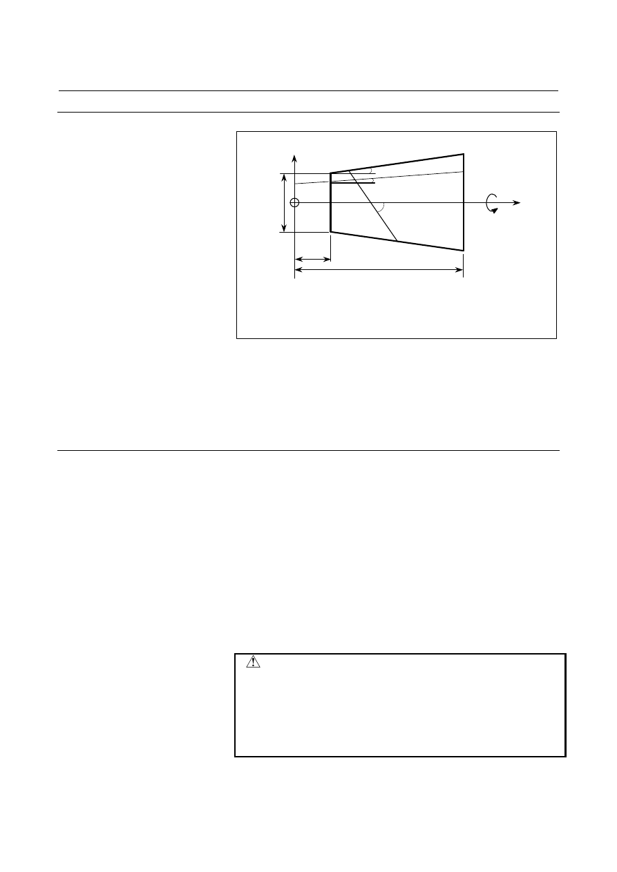
Example 

N10 G90 G01 X5.0 Z1.575 ;
N20 G02.3 X25.0 Z2.273 I3.0 J-45.0 K1.0 R1.238
F1000 Q1000 ;

Z

A

X

r = 3.0

Z(0) = 1.4

J = 45

°

I = 3.0

°

U = 5.0

X = 25.0

B = 2.0

°

Xe

Xs

Xs: Start point on the

X-axis

Xe: End point on the

X-axis


The start point and end point of the Z-axis and the constant R are 
obtained from the following expressions: 

Start point on the Z-axis 

(0)

*

)

tan(

Z

Xs

B

+

=


End point on the Z-axis 

(0)

*

)

tan(

Z

Xe

B

+

=


)

tan(

*

/2

I

U

r

R

=


Limitation 
  - Cases where linear interpolation is performed 

Even when the G02.3 or G03.3 mode is set, linear interpolation is 
performed in the following cases: 

  When the linear axis specified in parameter No. 5641 is not 

specified, or the amount of movement on the linear axis is 0 

  When the rotary axis specified in parameter No. 5642 is specified 

  When the amount for dividing the linear axis (span value) is 0 


 - Tool compensation 

The tool compensation functions (tool length compensation, tool 
radius/tool nose radius compensation, and 3-dimensional cutter 
compensation) cannot be used in the G02.3 or G03.3 mode. 


 CAUTION 


The amount for dividing the linear axis for 
exponential interpolation (span value) affects figure 
precision. However, if an excessively small value is 
set, the machine may stop during interpolation. Try 
to specify an optimal span value depending on the 
machine being used. 


B-63944EN/03

 PROGRAMMING 

4.INTERPOLATION FUNCTIONS


- 109 - 

4.12 

SMOOTH INTERPOLATION (G05.1) 

 
Either of two types of machining can be selected, depending on the 
program command. 


For those portions where the accuracy of the figure is critical, 
such as at corners, machining is performed exactly as specified 
by the program command.   


For those portions having a large radius of curvature where a 
smooth figure must be created, points along the machining path 
are interpolated with a smooth curve, calculated from the 
polygonal lines specified with the program command (smooth 
interpolation). 

In this manner, high-speed, high-precision machining can be 
performed. 
 

Format 

G05.1Q2X0Y0Z0 ; 

Starting of smooth interpolation mode

      : 
G05.1Q0 ; 

Cancellation of smooth interpolation mode


Explanation 
  - Characteristics of smooth interpolation 

To machine a part having sculptured surfaces, such as metal moldings 
used in automobiles and airplanes, a part program usually 
approximates the sculptured surfaces with minute line segments. As 
shown in the following figure, a sculptured curve is normally 
approximated using line segments with a tolerance of about 10 

µ

m. 

Enlarged 

10

µ

: Specified point 


4.INTERPOLATION FUNCTIONS

 PROGRAMMING 

B-63944EN/03


- 110 - 

When a program approximates a sculptured curve with line segments, 
the length of each segment differs between those portions that have 
mainly a small radius of curvature and those that have mainly a large 
radius of curvature. The length of the line segments is short in those 
portions having a small radius of curvature, while it is long in those 
portions having a large radius of curvature. Because linear 
interpolation controls the tool movement exactly as programmed so as 
not to let the tool depart from the path specified by a part program, 
machining is performed exactly along line segments with which a 
sculptured curve is approximated. Consequently, when a curve with a 
large radius of curvature and a moderate curvature change is machined, 
the corners of line segments may become apparent. Such concave and 
convex portions, produced as a result of machining performed exactly 
as specified, are found troublesome when a smooth surface must be 
obtained by finishing. 

Profile  

Portions having mainly 
a small radius of 
curvature 

Portions having mainly 
a large radius of 
curvature 

Example of machined 
parts 

Automobile parts 

Decorative parts, such 
as body side moldings

Length of line segment 

Short 

Long 

Resulting surfaces 
produced using 
high-precision contour 
control 

Smooth surface even 
when machining is 
performed exactly as 
specified by a program 

Uneven surfaces may 
result when machining 
is performed exactly as 
specified by a program


Example of uneven surfaces (polygon) resulting from machining that precisely follows the line segments. 


In smooth interpolation mode, the CNC automatically determines, 
according to the program command, whether an accurate figure is 
required, such as at corners, or a smooth figure is required where the 
radius of curvature is large. If a block specifies a travel distance or 
direction which differs greatly from that in the preceding block, 
smooth interpolation is not performed for that block. Linear 
interpolation is performed exactly as specified by the program 
command. Programming is thus very simple. 
 
Specifying G5.1 Q2 also enables AI contour control to be turned on at 
the same time. The automatic velocity control by AI contour control 
reduces impacts on the machanical system. Specifying G5.1 Q0 
cancels the smooth interpolation mode. The AI contour control mode 
is also canceled at the same time. 

B-63944EN/03

 PROGRAMMING 

4.INTERPOLATION FUNCTIONS


- 111 - 


Interpolated by smooth curve

Interpolated by smooth curve

(Example) 

N17 

N16 

N1 

N2 

N15

N14

N13

N12

N11

N10 

N9 

N3 

N4

N5

N6

N7

N8

Linear interpolation

Linear interpolation 

N17 

N16 

N1 

N2 

N15

N14

N13

N12

N11

N10 

N9 

N3 

N4

N5

N6

N7

N8


  - Conditions for performing smooth interpolation 

Smooth interpolation is performed when all the following conditions 
are satisfied. If any of the following conditions is not satisfied for a 
block, that block is executed without smooth interpolation then the 
conditions are checked for the next block. 
(1)  The machining length specified in the block is shorter than the 

length specified with parameter No. 8486. 

(2)  The machining length is other than 0. 
(3)  The modes are:     
 G01 

 : 

Linear 

interpolation 


G13.1 

:  Polar coordinate interpolation cancel 


G15  

:  Polar coordinate command cancel 


G40  

:  Tool radius/tool nose radius compensation cancel   


(except for 3-dimensional cutter compensation) 

 G64 

 : 

Cutting 

mode 

 G80 

 : 

Canned 

cycle 

cancel 

 G94 

 : 

Feed 

per 

minute 

(4)  Machining is specified only along the axes specified with 

G05.1Q2.  

(5)  The block is judged to be unsuitable for smooth interpolation, as 

performed with the internal algorithm of the CNC.     


  - Commands which cancel smooth interpolation 

(1)  Auxiliary and second auxiliary functions 
(2)  M98, M99 :  Subprogram call 

M198 

 :  Calling a subprogram in external memory 

4.INTERPOLATION FUNCTIONS

 PROGRAMMING 

B-63944EN/03


- 112 - 


  - Checking the smooth interpolation mode 

Diagnostic data (No. 5000#0) indicates whether the smooth 
interpolation mode is enabled in the current block. 
If the smooth interpolation mode is enabled, "smooth interpolation on" 
bit is set to 1. 
 

Limitation 
 - Controlled axes 

Smooth interpolation can be specified only for the X-, Y-, and Z-axes 
and any axes parallel to these axes (up to three axes at one time). 
 

Example 

<Example program for smooth interpolation> 


N10  X-1000  Z350  ;  

   .  

N11  X-1000  Z175  ;  

   .  

N12  X-1000  Z25  ;    

G91  ;   

N13  X-1000  Z- 50  ;  

G05. 1  Q2  X0  Y0  Z0  ;  N14  X-1000  Z- 50  ;  
N01  G01  X1000  Z-300  ;  N15  X-1000  Z50  ;    
N02  X1000  Z-200  ;   

N16  X-1000  Z200  ;  

N03  X1000  Z-50  ;   

N17  X-1000  Z300  ;  

N04  X1000  Z50  ;  

G05. 1  Q0  ;    

N05  X1000  Z50  ;   

   .    

N06  X1000  Z-25  ;   

   .    

N07  X1000  Z-175  ;    


N08  X1000  Z-350  ;   


N09  Y1000  ;    


Interpolated by smooth curve 

Interpolated by smooth curve 

(Example) 

N17 

N16 

N1 

N2 

N15

N14

N13

N12

N11

N10 

N9 

N3 

N4

N5

N6

N7

N8

Linear interpolation


B-63944EN/03

 PROGRAMMING 

4.INTERPOLATION FUNCTIONS


- 113 - 

4.13 

NANO SMOOTHING 


Overview 

When a desired sculptured surface is approximated by minute 
segments, the nano smoothing function generates a smooth curve 
inferred from the programmed segments and performs necessary 
interpolation. 
The nano smoothing function infers a curve from a programmed 
figure approximated with segments within tolerance. If the spacing 
between adjacent inflection points or programmed points is not 
constant, this function can generate a smoother curve than the 
conventional smooth interpolation function. 
The interpolation of the curve reduces the segment approximation 
error, and the nano-interpolation makes the cutting surface smoother. 
The interpolation of the curve reduces the segment approximation 
error, and the nano interpolation makes the cutting surface smoother. 
Nano smoothing 2 allows the basic three axes (X, Y, and Z) or their 
parallel axes as well as two rotation axes to be specified. This enables 
five-axis machining (including rotation axes) to produce very smooth 
finished surfaces and so finds applications such as machining of 
smooth workpiece side faces. 
In addition, this function can be used with tool center point control 
(type 1 (G43.4)). This eliminates the necessity of modifying a 
program when the tool length is changed. 
For this function, the AI contour control option is required. 
For nano smoothing 2, the nano smoothing option is required. 
 

Format 

G5.1 Q3 Xp0 Yp0 Zp0 [

α

0] [

β

0] ;  : 

Nano smoothing mode on


G5.1 Q0 ; 

Nano smoothing mode off


Xp  : X-axis or an axis parallel to the X-axis 
Yp  : Y-axis or an axis parallel to the Y-axis 
Zp  : Z-axis or an axis parallel to the Z-axis 

α

β

 :  Rotary axis 


NOTE 

1  Specify G5.1 alone in a block. (Avoid specifying 

any other G code in the same block.) 

2  Specify position 0 for the axis programmed in the 

nano smoothing mode on block. The specified axis 
is subjected to nano smoothing, but no movement 
is made even in the absolute programming mode. 


4.INTERPOLATION FUNCTIONS

 PROGRAMMING 

B-63944EN/03


- 114 - 

Nano smoothing 2 enables specification of the basic three axes (X-, Y-, 
and Z-axes) or their parallel axes as axes on which to perform nano 
smoothing, as well as two rotary axes. 
If executing nano smoothing 2 simultaneously with tool center point 
control (type 1 (G43.4)), enable tool center point control (G43.4) first 
and then enable nano smoothing 2 (G5.1 Q3). To cancel them, cancel 
nano smoothing 2 (G5.1 Q0) first and then cancel tool center point 
control (G49). 
 
Example : 

O0010 
… 
G43.4 H1 P0; 
G5.1 Q3 X0 Y0 Z0 B0 C0; 
… 
G5.1 Q0; 
G49; 
… 
M30; 

Nano smoothing 2 

Tool center point control 


  - Nano smoothing mode 

Specifying G5.1 Q3 selects the nano smoothing mode. An axis of 
nano smoothing is specified in the same block. The basic three axes 
(X, Y, and Z) and their parallel axes can be specified as the axis of 
nano smoothing. In the nano smoothing mode, nano smoothing is 
performed in a block which satisfies the conditions described below.   
Nano smoothing is cancelled in a block which does not satisfy the 
conditions. 
Specifying G5.1 Q3 also enables AI contour control. The automatic 
velocity control by AI contour control reduces impacts on the 
mechanical system. 
Specifying G5.1 Q0 cancels the nano smoothing mode. The AI 
contour control mode is also cancelled at the same time. 
Making a reset also cancels the nano smoothing mode. 

B-63944EN/03

 PROGRAMMING 

4.INTERPOLATION FUNCTIONS


- 115 - 

  - Conditions to enable nano smoothing 

Nano smoothing is enabled when the following conditions are 
satisfied. Nano smoothing is cancelled in a block which does not 
satisfy the conditions. A decision is made to perform nano smoothing 
from the next block. 
In the programmed block length and the difference in angle between 
adjacent programmed blocks in the conditions listed below, only the 
basic three axes (or their parallel axes) are considered, and the rotation 
axes are excluded. When the nano smoothing mode is canceled in a 
block when these conditions are satisfied, nano smoothing for the 
rotation axes is not performed, either. 
 
<1>  The programmed block length is shorter than the length specified 

in parameter No. 8486. 

<2>  The programmed block length is longer than the length specified 

in parameter No. 8490. 

<3> The difference in angle between adjacent programmed blocks is 

smaller than the value specified in parameter No. 8487. 

<4>  The current mode is one of the following: 

 Linear interpolation 

  Feed per minute 

  Tool radius compensation cancel 

  Canned cycle cancel 

 Scaling cancel 

  Macro modal call cancel 

  Constant surface speed control cancel 

 Cutting mode 

  Coordinate system rotation / 3-dimensional coordinate system 

conversion cancel 

  Polar coordinate cancel 

  Normal-direction control cancel 

  Polar coordinate interpolation cancel 

  Programmable mirror image cancel 

  Polygon turning cancel 

<5>  No one-shot G code is specified in the block. 
<6>  Buffering is not suppressed in the block. 
<7> A movement just on the axis of nano smoothing is specified in 

the block. 


  - Checking the nano smoothing mode 

Diagnostic data (No. 5000) indicates whether the nano smoothing 
mode is enabled in the current block. 
If the nano smoothing mode is enabled, the "smoothing on" bit is set 
to 1. 


Content      ..     17      18      19      20     ..