FANUC Series 0i-MODEL F Plus. CONNECTION MANUAL (FUNCTION) - page 380
 

  Index      Manuals     FANUC Series 0i-MODEL F Plus. CONNECTION MANUAL (FUNCTION) B-64693EN-1/01


Search            copyright infringement  


Content      ..     378      379      380      381     ..


FANUC Series 0i-MODEL F Plus. CONNECTION MANUAL (FUNCTION) - page 380


B-64693EN-1/01


APPENDIX


- 2997 - 

D. PARAMETER TUNING FOR 

ENHANCEMENT OF 
MACHINING QUALITY 

2 Tuning if there is problem 

2-1 Tuning of AI contour control 

Tune the parameter according to priority for each purpose (Reducing vibration, Reducing machining error, 
Enhancing machining quality, Reducing cycle time). 
 

Tuning priority 

Priority  High : 

◊◊

 / Middle : 

 / Low : None 

Purpose 

Machining 

Tuning item (Upper : Parameter number / Lower : Tuning rage) 

Acc. rate for 

Acc./Dec. 

before 

interpolation 


(No.1660) 

Time const. 

for bell-type 

Acc./Dec. 

before 

interpolation 

(No.1772) 

Time const. 

for Acc./Dec. 

after 

interpolation 


(No.1769) 

Corner feed 

rate 

difference 


(No.1783) 

Allowable 

acc. rate for 

circular 

interpolation 


(No.1735) 

Allowable 

acc. rate for 

small line 

blocks 


(No.1737) 

Parts 

250 to 5000 

16 to 64 

8 to 48 

150 to 1000 

200 to 3750 

200 to 3750 

Die-mold 

8 to24 

Reducing 

vibration 

Parts 

Decrease 


Increase 


Increase 

◊◊


Decrease 


Decrease 

Decrease 

Die-mold 

Increase 

Reducing 

machining 

error 

Parts 

Decrease 

Increase 

Decrease 

◊◊


Decrease 


Decrease 


Decrease 

Die-mold 

Decrease 

Decrease 

Decrease 


Enhancing 

machining 

quality 

Parts 

Decrease 

Increase 

Increase 

◊◊


Decrease 

Decrease 

Decrease 

Die-mold 

Increase 


Decrease 

◊◊


Decrease 


Reducing 

cycle time 

Parts 

Increase 


Decrease 

◊◊


Decrease 

Increase 


Increase 

Increase 

Die-mold 

-   

In case that the priority of parameter is same, tune the parameter with high effect 
after confirming the effect of each parameter. 


2-2 Countermeasure of vibration for lower frequency 

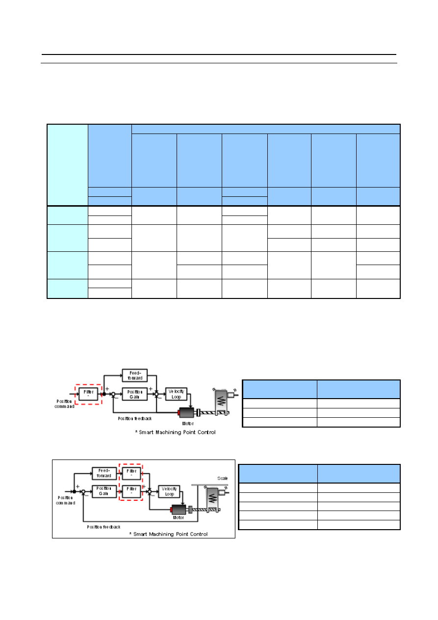
Avoidance of machining point vibration (below 50Hz) after Acc./Dec. by Smart machining point control. 
 
Semi-closed system 


Full-closed system 


Parameter 

number 

Recommended 

value 

No.2564#1 

No.2638[0.1Hz] 

Vibration freq.[Hz]×10 

No.2639 

10 

Parameter 

number 

Recommended 

value 

No.2570#4 

No.2571#3 

No.2647[0.1Hz] 

Vibration freq.[Hz]×10 

No.2648 

30 

No.2649 

2510 


APPENDIX


B-64693EN-1/01 

- 2998 - 

D. PARAMETER TUNING FOR 

ENHANCEMENT OF 
MACHINING QUALITY 

D.2 

SUPPLEMENT 

Supplement A. Details of AI contour control 

AI contour control is the function to possible high speed and high precision machining with low machine 
vibration and low machining error by following four functions. 
The following four functions can be easily understood as the comparison to driving a car. 


B-64693EN-1/01


APPENDIX


- 2999 - 

D. PARAMETER TUNING FOR 

ENHANCEMENT OF 
MACHINING QUALITY 

Acc./Dec. before interpolation, Bell-type Acc./Dec. before interpolation, 
Acc./Dec. after interpolation 

Acc./Dec. before interpolation is function to accelerate or decelerate for command feed-rate before CNC 
interpolates machining program command. Acc./Dec. after interpolation is function to accelerate or 
decelerate for each axis feed-rate after CNC interpolates. 
In Acc./Dec. before interpolation, set acceleration rate (No.1660), and it is possible to produce smooth 
feed-rate curve by bell-type Acc./Dec. before interpolation (No.1772). 
Acc./Dec. before interpolation achieve Acc./Dec. without machining error because CNC interpolates 
smoothed feed-rate curve with Acc./Dec. before interpolation. 
It is possible to more smooth feed-rate curve by using Acc./Dec. after interpolation (No.1769), but 
Acc./Dec. after interpolation makes machining error because it makes after CNC interpolation. 


APPENDIX


B-64693EN-1/01 

- 3000 - 

D. PARAMETER TUNING FOR 

ENHANCEMENT OF 
MACHINING QUALITY 

Difference between Acc./Dec. before interpolation and Acc./Dec. after interpolation 

Acc./Dec. before interpolation achieve Acc./Dec. without machining error, but feed-rate of each axis is 
not continuous in the corner and it might cause machine vibration or shock. 
It is possible to smooth the discontinuous feed-rate point by using Acc./Dec. after interpolation that 
accelerate or decelerate for each axis feed-rate after CNC interpolates, but the smoothing of feed-rate by 
Acc./Dec. after interpolation occurs machining error as described above. 
So, both Acc./Dec. before interpolation and Acc./Dec. after interpolation are necessary functions and it is 
important to use well-balance. 


B-64693EN-1/01


APPENDIX


- 3001 - 

D. PARAMETER TUNING FOR 

ENHANCEMENT OF 
MACHINING QUALITY 

Corner feed rate difference 

In the corner, tangential feed-rate curve is smooth, but feed-rate change of each axis is large, so it might 
cause machine vibration. In this case, machine vibration can be reduced by deceleration with corner 
feed-rate difference (No.1783) in the corner. 
Deceleration feed-rate is decided so that there is no difference of setting value of corner feed-rate 
difference for each axis or more. 
Feed-rate difference under the value of setting corner feed-rate difference in the corner can be smooth by 
Acc./Dec. after interpolation. And machining error is reduced by reducing feed-rate difference in the 
corner. 


Feed-rate in the corner is decided by parameter setting value of corner feed-rate difference and corner 
angle. 
In case of the same parameter setting value of corner feed-rate difference, if corner angle is smaller, 
feed-rate difference of each axis is made below parameter setting value by more deceleration in the 
corner. 
In case of the same corner angle, if parameter setting value of corner feed-rate difference is smaller, 
machine vibration and machining error are reduced by more deceleration in the corner. 


APPENDIX


B-64693EN-1/01 

- 3002 - 

D. PARAMETER TUNING FOR 

ENHANCEMENT OF 
MACHINING QUALITY 

Allowable acceleration rate for curved surface 

In the curved surface, tangential feed-rate curve is smooth, but feed-rate change (=acceleration rate) of 
each axis is large, so it might cause machine vibration. Corner deceleration is not effective in the curved 
surface. Even if the curved surface is composed of small line segment blocks, corner deceleration is not 
effective because feed-rate difference between blocks is small. 
In this case, machine vibration can be reduced by limiting acceleration rate with allowable acceleration 
rate (No.1735, No.1737) in the curved surface. 
Moreover, as corner deceleration, machining error caused by Acc./Dec. after interpolation is reduced by 
deceleration in the curved surface. 
Different allowable acceleration rate value can be set for small line segment blocks (No.1737) and 
circular interpolation (No.1735). 


Feed-rate in the curved surface is decided by parameter setting value of allowable acceleration and curved 
rate. 
In case of the same parameter setting value of allowable acceleration, if curved rate is larger, acceleration 
rate of each axis is made below parameter setting value by more deceleration in the curved surface. 
In case of the same curved rate, if parameter setting value of allowable acceleration is smaller, machine 
vibration and machining error are reduced by more deceleration in the curved surface. 


B-64693EN-1/01


APPENDIX


- 3003 - 

D. PARAMETER TUNING FOR 

ENHANCEMENT OF 
MACHINING QUALITY 

Supplement B. Servo tuning for higher response 

Tuning for higher servo stiffness and for improvement of machining accuracy. 
 

Tuning of velocity Loop gain and filter 

Measure frequency response by SERVO GUIDE and increase velocity loop gain with keeping the 
following three conditions. 
 
(1)  Open loop gain below -6dB 

where phase = -180 deg 

(2)  Open loop phase above -150 deg 

where gain = 0dB 

(3)  Closed loop gain below +5dB 
 

-180deg

0dB

(1)

(2)

(3)

-150deg

-6dB

5dB

Red 

Open loop

Blue

Closed loop


When vibration occurs, refer to the following table. 

Vibration frequency 

Method of tuning 

Standard parameter range of filter 

Lower 200Hz 

Decrease velocity loop gain 


200 to 400Hz 

Apply resonance elimination filter 

Attenuation bandwidth  : 60 to 100Hz 
Damping              : 0 to 50% 

400 to 1000Hz 

Apply resonance elimination filter 

Attenuation bandwidth  : 100 to 200Hz 
Damping              : 0 to 10% 

Upper 1000Hz 

Apply resonance elimination filter 

Attenuation bandwidth  : 300 to 600Hz 
Damping              : 0 to 10% 


Tuning of velocity feed-forward 

Setting of feed-forward coefficient calculated by following formula 

Parameter 

number 

Inertia information 

No inertia information 

No.2069 

100 × 


100 

No.2145 


APPENDIX


B-64693EN-1/01 

- 3004 - 

D. PARAMETER TUNING FOR 

ENHANCEMENT OF 
MACHINING QUALITY 


Tuning of Smart Backlash Comp. 

Tuning of Smart Backlash Compensation with DBB and SERVO GUIDE 
1. 

Measure backlash by DBB and measure length of ball screw and estimated load torque by SERVO 
GUIDE 

2. 

Set measured backlash (Backlash is able to be measured by dial gauge etc. instead of DBB.) 

3. 

Set length of ball screw and change value of estimated load torque when axis reversing 


Content      ..     378      379      380      381     ..