FANUC Series 0i-MODEL F Plus. CONNECTION MANUAL (FUNCTION) - page 353
 

  Index      Manuals     FANUC Series 0i-MODEL F Plus. CONNECTION MANUAL (FUNCTION) B-64693EN-1/01


Search            copyright infringement  


Content      ..     351      352      353      354     ..


FANUC Series 0i-MODEL F Plus. CONNECTION MANUAL (FUNCTION) - page 353


18. DIAGNOSIS FUNCTION


B-64693EN-1/01


- 2778 - 

- Change of displayed page 

Displayed page is switched by pressing page key 


  / 


- Change of displayed axis 

Displayed axis is switched by pressing cursor key 


  / 


- Preservation of data when alarm is occurred 

When status display is in the state of [SAMPLING], and servo alarm/spindle alarm is occurred newly, 
"Data at the latest alarm occurrence" and "Data of 1-4 immediately before occurrence of the alarm" of the 
alarm occurrence axis are preserved. 
As a result, [SAMPLING] of status display on the right of the screen changes into [LATCHED]. 
 

NOTE 


As for both servos and spindles, when the alarm as two or more axes at the 
same time is occurred, only the data of the axis of the least index of an axis is 
preserved. 


- Clear of preserved data 

After  releasing all servo/spindle alarm, clear "Data at the latest alarm occurrence"  and  "Data of 1-4 
immediately before occurrence of the alarm". 
As a result, [LATCHED]  of status display on the right of the screen changes into [SAMPLING]. 
Moreover, the waveform  data (various data of each axis) displayed on the trouble diagnosis graphic 
screen is cleared at the same time. 
 

Clear operation procedure of preserved data (for 8.4/10.4-inch display unit) 

Procedure 

The soft  key display changes as follows if soft  key  [(OPER)]  is  pressed on the trouble diagnosis 
monitor screen, the trouble diagnosis graphic screen or the trouble diagnosis parameter screen. 
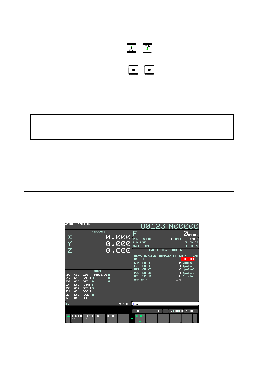
(The below figure is a trouble diagnosis monitor screen.) 


Fig.18.4.4 (d) Trouble diagnosis monitor screen (10.4-inch display unit) 


B-64693EN-1/01


18. DIAGNOSIS FUNCTION


- 2779 - 

Press the soft key [CLEAR]. 
The soft key display changes as follows. 
Press the soft key [CAN] when you cancel the clear operation. 


Fig.18.4.4 (e) Trouble diagnosis monitor screen (10.4-inch display unit) 


Press the soft key [EXEC]. 
[LATCHED] of status display on the right of the screen changes into [SAMPLING] 


Fig.18.4.4 (f) Trouble diagnosis monitor screen (10.4-inch display unit) 


18. DIAGNOSIS FUNCTION


B-64693EN-1/01


- 2780 - 

Clear operation procedure of preserved data (for 15/19-inch display unit) 

Procedure 

The horizontal soft key [CLEAR] deletion is displayed on the trouble diagnosis monitor screen, the 
trouble diagnosis graphic screen or the trouble diagnosis parameter screen. 

Press the horizontal soft key [CLEAR]. 
Press the horizontal soft key [CAN] when you cancel the clear operation. 

Press the horizontal soft key [EXEC]. 
[LATCHED] of status display on the right of the screen changes into [SAMPLING] 


18.4.5 

Trouble diagnosis graphic screen 

Outline 

The waveform data immediately before occurrence of the alarm necessary for the diagnosis when the 
servo alarm / spindle alarm is occurred is displayed. 
 

Trouble diagnosis graphic screen 

The servo data / spindle data for a few seconds immediately before occurrence of the alarm is displayed 
by waveform on the screen. The data of maximum 4 kinds can be displayed at the same time. 
The displayed data is set on the trouble diagnosis parameter screen. 
 

Display procedure of trouble diagnosis graphic screen (for 8.4/10.4-inch display 
unit) 

Procedure 

Press function key 


Press the continuous menu key 


  until soft key [W.GRPH] appears. 

Press soft key [W.GRPH]. 

Press soft key [G-ADJ.]. 


Fig.18.4.5 (a) Trouble diagnosis graphic screen (10.4-inch display unit) 


- Contents of display 

(1)  Red vertical line shows the position (time) in which the alarm is occurred.. 
(2)  The date when the alarm was occurred is displayed. 

(1) 

(2) 

B-64693EN-1/01


18. DIAGNOSIS FUNCTION


- 2781 - 

Display procedure of trouble diagnosis graphic screen (for 15/19-inch display unit) 

Procedure 

Press function key 


Press the vertical soft key [NEXT PAGE] until vertical soft key [W.GRPH] appears. 

Press the vertical soft key [W.GRPH]. 

Press the vertical soft key [G-ADJ.]. 


Operation 

- Change of position and magnification 

When Soft key [G-ADJ.] is pressed, the following soft keys appear. 
 

[<] [W.PRM ] [G-ADJ.] [TRB_LV] [      ]  [(OPRT)] [  ] 


[<] [H-DOBL] [H-HALF] [

←TIME]  [TIME→]  [      ]  [


[<] [ CH-1 ] [ CH-2 ] [ CH-3 ] [ CH-4 ] [      ]  [


[<] [WAV.EX] [WAV.RE] [

WAV.↑]  [WAV.↓]  [      ]  [  ] 


Soft key [H-DOBL] 

: The length of the time base is expanded. 

Soft key [H-HALF] 

: The length of the time base is reduced. 

Soft key [TIME

: The time base is moved to the left side. 

Soft key [TIME

: The time base is moved to the right side. 

Soft key [CH-1] 

: The operation to the waveform of channel 1 is selected. 

Soft key [CH-2] 

: The operation to the waveform of channel 2 is selected. 

Soft key [CH-3] 

: The operation to the waveform of channel 3 is selected. 

Soft key [CH-4] 

: The operation to the waveform of channel 4 is selected. 

Soft key [WAV.EX] 

: The length of the spindle is expanded to the selected waveform. 

Soft key [WAV.RE] 

: The length of the spindle is reduced to the selected waveform. 

Soft key [WAV.

: The selected waveform is moved for above. 

Soft key [WAV.

: The selected waveform is moved below. 


The time scale is a common scale for the channel 1,2,3 and 4.


The position and magnification of the height scale can be set for each channel.


18. DIAGNOSIS FUNCTION


B-64693EN-1/01


- 2782 - 

Parameter setting for waveform display on the trouble diagnosis graphic 
screen 

The data kind and the data unit of the waveform data displayed on the trouble diagnosis graphic screen 
are displayed and set on the trouble diagnosis parameter screen. 
 

Display procedure of trouble diagnosis parameter screen (for 8.4/10.4-inch display 
unit) 

Procedure 

Press function key 


Press the continuous menu key 


  until soft key [W.GRPH] appears. 

Press soft key [W.GRPH]. 

Press soft key [W.PRM]. 


Fig. 18.4.5 (b) Trouble diagnosis parameter screen (10.4-inch display unit) 


Display procedure of trouble diagnosis parameter screen (for 15/19-inch display 
unit) 

Procedure 

Press function key 


Press the vertical soft key [NEXT PAGE] until vertical soft key [W.GRPH] appears. 

Press the vertical soft key [W.GRPH]. 

Press the vertical soft key [W.PRM]. 


B-64693EN-1/01


18. DIAGNOSIS FUNCTION


- 2783 - 

Explanation 

- Contents of display 

CHANNEL


Channel for waveform display. Maximum 4 channels can be used.  Set data from the first channel 
sequentially. 

 
AXIS : 

Axis for waveform display. Manual setting is available. In some cases Axis data is set automatically 
for diagnosis in trouble diagnosis guidance screen. 

 
DATA KIND : 

Data kind for waveform display. Manual setting is available. In some cases data kind is set 
automatically for diagnosis in trouble diagnosis guidance screen. 

 
DATA UNIT : 

Unit of display data. This data is set automatically according to data kind. Manual setting is invalid. 

 
FORECAST LV : 

This data decides boundary value to output trouble forecast signal. Manual setting is available. 

 
Guidance of setting each item : 

The guidance to the above setting each item is displayed. 


Operation 

- Data Setting 

Move cursor by Cursor key to the setting item. 

Input number by MDI key and press input key 


  to set data.   

The content of the following each items can be input by the above operation. 
 
AXIS : 

In case of servo axis, input control axis number. 
  (Example) Set "1" for first servo axis. 
In case of spindle axis, input "100 + spindle number". 
  (Example) Set "101" for first spindle axis. 


NOTE 


Set the index of an axis in the path system to the control axis number and the 
control spindle number for the multi path system. 

 
DATA KIND : 

Input data number value according to the following table. 


Table 18.4.5 (a) Data of Servo motor 

Data number 

Data kind 

Accumulated command pulse (pulse) 

Accumulated feedback pulse (pulse) 

Position error (pulse) 

Reference counter (pulse) 

Actual speed (1/min) 

Command current (%) 

Thermal simulation data (%) 

Torque (%) 

18. DIAGNOSIS FUNCTION


B-64693EN-1/01


- 2784 - 

Data number 

Data kind 

Disturbance level (%) 

10 

Optional data 

11 

R-phase current (%) 

12 

Effective current (%) 

13 

Pulse coder AMR data 

14 

Optional data 2 

20 

SV U CURRENT (A) 

21 

SV V CURRENT (A) 

22 

PS L1-L2 VOLT. (V) 

(NOTE 3) 

23 

PS L2-L3 VOLT. (V) 

(NOTE 3) 

24 

PS L3-L1 VOLT. (V) 

(NOTE 3) 

25 

PS L1 CURRENT (A) 

(NOTE 3) 

26 

PS L2 CURRENT (A) 

(NOTE 3) 

27 

PS L3 CURRENT (A) 

(NOTE 3) 

28 

PS DC LINK VOLT. (V)  (NOTE 3) 


Table 18.4.5 (b) Data of Spindle motor 

Data number 

Data 

15 

Actual speed (1/min) 

16 

Load meter (%) 

17 

Position error (pulse) 

18 

Actual speed (1/min)/(80msec) 

19 

Load meter (%)/(80msec) 

30 

SP U CURRENT (A) 

31 

SP V CURRENT (A) 

32 

PS L1-L2 VOLT. (V) 

(NOTE 3) 

33 

PS L2-L3 VOLT. (V) 

(NOTE 3) 

34 

PS L3-L1 VOLT. (V) 

(NOTE 3) 

35 

PS L1 CURRENT (A) 

(NOTE 3) 

36 

PS L2 CURRENT (A) 

(NOTE 3) 

37 

PS L3 CURRENT (A) 

(NOTE 3) 

38 

PS DC LINK VOLT. (V)  (NOTE 3) 


NOTE 

1  Each data kind is classified as follows as the combination to which the 

waveforms can be displayed at the same time. 
-  Data number :1 – 17 
-  Data number :18, 19 
-  Data number :20, 21, 30, 31 
-  Data number :22 - 28, 32 – 38 


Therefore, if the values other than the same combination as the data kind of 
another channel are set when the data number is input to the data kind, Warning 
"DATA SETTING ERROR" is displayed. 

2  The emergency must stop when the set point displays the data kind of 

waveforms of 20 or more number. 

3  The displayed values as Voltage and Current are approximate value and they 

have some error. If you want to know the precise values, measure them by 
exclusive equipments. 


B-64693EN-1/01


18. DIAGNOSIS FUNCTION


- 2785 - 

18.4.6 

Trouble forecast level setting screen 

Trouble forecast level of the servo motor is set in this screen. 
The breakdown level at the thermal simulation and disturbance level can be set. 
 

Explanation 


Thermal simulation 

The calorific value of the motor and the amplifier is simulated based on a real current of the servo motor. 
The alarm of "SOFTTHERMAL(OVC)" is occurred so that the motor or the amplifier might cause over 
heat when this thermal simulation data reaches 100%. 
Data value increases in the following cases. 
1) 

Operating that frequency of acceleration and deceleration is high. 

2) 

Operating to which state with very large cutting load continues. 

3) 

The machine did not work according to the instruction though the motor output a full torque by the 
contact etc. of the machine and work. 


Disturbance level 

The disturbance level shows the torque that the motor receives from the machine excluding the torque to 
accelerate/decelerate the motor and the machine inertia in the output torque of the motor. 
1) 

The machine came in contact with work. 

2) 

The cutting load has increased. 

 
An increase in these values is observed by this function, and warning can be occurred before the accident 
to the machine and occurrence of the alarm. 
 

Display procedure of trouble forecast level setting screen (for 8.4/10.4-inch display unit) 

Procedure 

Press function key 


Press the continuous menu key 


  until soft key [W.GRPH] appears. 

Press soft key [W.GRPH]. 

Press soft key [TRB LV]. 


Fig.18.4.6 (a) Trouble forecast level setting screen (10.4-inch display unit) 

(3) 

(2) 

(1) 


Content      ..     351      352      353      354     ..