FANUC Series 0i-MODEL F Plus. CONNECTION MANUAL (FUNCTION) - page 230
10. SPINDLE SPEED FUNCTION
B-64693EN-1/01
- 1794 -
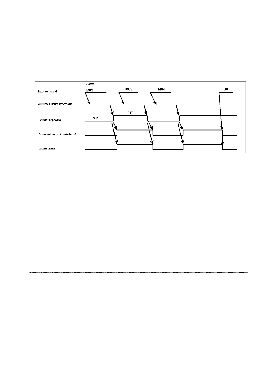
Spindle stop signal *SSTP<Gn029.6>
[Classification] Input signal
[Function] This signal stops the command output to the spindle.
[Operation] When this signal becomes 0, the command output to the spindle becomes 0, resulting in
the enable signal becoming 0. So, M05 is not output. When this signal becomes 1, the
command output to the spindle resumes its previous value, resulting in the enable signal
becoming 1.
The timing chart above is illustrative only. To be more precise, follow a timing chart that
meets the specification of the speed control unit for the spindle motor in use.
-
Keep this signal set to 1 unless it is used.
-
The CNC uses the commands M03, M04, and M05 to send only code and strobe
signals.
Individual spindle stop signals
*SSTP1<Gn027.3> *SSTP2<Gn027.4> *SSTP3<Gn027.5> *SSTP4<Gn026.6>
[Classification] Input signal
[Function] These signals are usable only during multi-spindle control.
They cause the respective spindles to stop.
*SSTP1 1: Does not make the output to the first spindle 0 min
-1
.
0: Makes the output to the first spindle 0 min
-1
.
*SSTP2 1: Does not make the output to the second spindle 0 min
-1
.
0: Makes the output to the second spindle 0 min
-1
.
*SSTP3 1: Does not make the output to the third spindle 0 min
-1
.
0: Makes the output to the third spindle 0 min
-1
.
*SSTP4 1: Does not make the output to the fourth spindle 0 min
-1
.
0: Makes the output to the fourth spindle 0 min
-1
.
Spindle speed override signals SOV0 to SOV7<Gn030>
[Classification] Input signal
[Function] These signals enable an override of 0% to 254% of the S command value sent to the CNC
to be applied to the spindle in 1% increments.
[Operation] Specify an override value in binary, using the 8 bits SOV0 to SOV7.
The spindle speed override specified with these signals becomes disabled, and an override
of 100% is applied to the spindle speed during:
-
Tapping cycle (for the M series, G84 and G74 or, for the T series, G84 and G88)
-
Threading mode (for the M series, G33 or, for the T series, G32, G92, and G76)
→ Specify an override of 100% unless this function is used.
(An override of 0% is applied, preventing spindle rotation.)