FANUC Series 0i-MODEL F Plus. CONNECTION MANUAL (FUNCTION) - page 228
 

  Index      Manuals     FANUC Series 0i-MODEL F Plus. CONNECTION MANUAL (FUNCTION) B-64693EN-1/01


Search            copyright infringement  


Content      ..     226      227      228      229     ..


FANUC Series 0i-MODEL F Plus. CONNECTION MANUAL (FUNCTION) - page 228


10. SPINDLE SPEED FUNCTION


B-64693EN-1/01


- 1778 - 

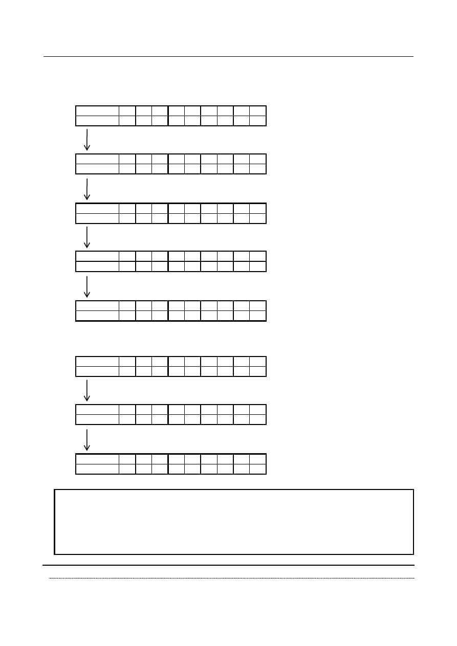
G25 mode, valid state of the parameters of spindle speed fluctuation detection is held. After that, when 
mode is change into G26 mode again, this valid state is applied. Examples are shown below. 


NOTE 


Alarm PS1305 is issued because value of specified address P, Q, R, I in the 
machining program is out of valid data range. At this time, about address of 
value out of valid data range, if type of parameters Nos. 4921 to 4924 (dp, dq, 
dr, di) are valid before machining program, type of parameters Nos. 4921 to 
4924 (dp, dq, dr, di) are still valid. 


Signal 

Spindle speed fluctuation detection alarm signal SPAL <Fn035.0> 

    [Classification]  Output signal 

G25 mode 


G26 mode 


dp 


dq 


dr 


di 


  G26 Rr Ii ;


G25 mode 


G26 mode 


dp 


dq 


dr 


di 


(Example 4) 


clear


(bit 0 (G26) of parameter No.4902 is set to 1)


G25 mode 


G26 mode 


dp 


dq 


dr 


di 


  G25 ;


G25 mode 


G26 mode 


dp 


dq 


dr 


di 


  G26 ;


G25 mode 


G26 mode 


dp 


dq 


dr 


di 


G25 mode 


G26 mode 


dp 


dq 


dr 


di 


  G25 ;


G25 mode 


G26 mode 


dp 


dq 


dr 


di 


G25 mode 


G26 mode 


dp 


dq 


dr 


di 


(Example 3) 


clear


(bit 0 (G26) of parameter No.4902 is set to 1)


B-64693EN-1/01


10. SPINDLE SPEED FUNCTION


- 1779 - 


  [Function]  This signal indicates that the actual spindle speed is not within a tolerance to the specified 

speed. 


[Output cond.]  The signal becomes logical “1” when: 

The actual spindle speed goes out of tolerance to the specified speed. 

The signal becomes logical “0” when: 

No alarm OH0704 condition has been detected for spindle speed fluctuation. 

An alarm condition is cleared by resetting the NC when the signal is logical 1. 


Signal address 


#7 

#6 

#5 

#4 

#3 

#2 

#1 

#0 

Fn035 


SPAL 


Parameter 


#7 

#6 

#5 

#4 

#3 

#2 

#1 

#0 

4900 


FDTs 

UDPs 


FDEs 


FLRs 


[Input type]  Parameter input 


[Data type]  Bit spindle 


#0  FLRs

  When the spindle speed fluctuation detection function is used, the unit of parameters No. 

4911(q),  No. 4912(r),  No. 4921(dq),  No. 4922(dr) and diagnoses  No.  1591,  No.  1592 
(allowable ratio and fluctuation ratio) is: 
0: 

1%. 

1: 

0.1%. 


#4  FDEs

  Spindle speed fluctuation detection function is: 

0: 

Enabled. 

1: 

Disabled. 

If the position coder selection signal is selected for a spindle for which this parameter is 1, 
the target spindle of spindle speed fluctuation detection remains unchanged. Spindle 
speed fluctuation detection  stays enabled for the spindle for which spindle speed 
fluctuation detection was enabled before the selection of the position coder selection 
signal. 
An example is given below. 
[Example] 
 

Bit 4 (FDE) of parameter No.4900 (Workpiece spindle) = 0 


Bit 4 (FDE) of parameter No.4900 (Tool spindle) = 1 


Even when the position coder selection signal is switched from the workpiece 
spindle to the tool spindle, the target spindle of spindle speed fluctuation detection 
remains unchanged, that is, the function stays enabled for the workpiece spindle. 


Workpiece 

spindle 

Tool spindle 

Selected-

spindle 

PCS 

Workpiece 

spindle 

Tool spindle 

Selected-

spindle 

PCS 


Spindle speed fluctuation 

detection is enabled for the 

workpiece spindle. 

Spindle speed fluctuation 

detection is enabled for the 

workpiece spindle. 


Note) The selected spindle varies depending on the state of the position coder selection 

signal. 


10. SPINDLE SPEED FUNCTION


B-64693EN-1/01


- 1780 - 

NOTE 

1  If bit 4 (FDE) of parameter No.4900 is 0 for all spindles, spindle 

speed fluctuation detection is enabled for the spindle selected with 
the position coder selection signal as is conventionally. If the bit 4 
(FDE) of parameter No.4900 is 1 for all spindles, spindle speed 
fluctuation detection is enabled for the spindle selected with the 
position coder selection signal. 

2  When the bit 4 (FDE) of parameter No.4900 is 0 for all spindles, 

setting the bit 4 (FDE) of parameter No.4900 for the spindle 
selected with the position coder selection signal to 1 does not 
cause an immediate change to the target spindle, which stays as 
the target until the next position coder selection signal is issued. 

3  If the bit 4 (FDE) of parameter No.4900 for the first spindle is 1 and 

the first spindle is the tool spindle when the power is turned on, 
spindle speed fluctuation detection remains enabled for the first 
spindle until a spindle for which the bit 4 (FDE) of parameter 
No.4900 is 0 is selected. 


#6  UDPs

  About parameters of spindle speed fluctuation detection at power-on: 

0: 

Parameters Nos. 4911 to 4914 (p, q, r, i) are valid. 

1: 

Parameters Nos. 4921 to 4924 (dp, dq, dr, di) are valid. 


NOTE 


This parameter (UDPs) is referenced at only power-on. So, even 
when this parameter (UDPs) is changed after power-on, valid 
parameters about spindle speed fluctuation detection are not 
changed. 


#7  FDTs

  Spindle speed fluctuation detection is started:   

0: 

When the actual spindle speed reaches a specified range or when the time specified 
with valid parameter (p(No.4914) or dp(No.4924)) elapses. 

1: 

When the time specified with valid parameter (p(No.4914) or dp(No.4924)) elapses. 


#7 

#6 

#5 

#4 

#3 

#2 

#1 

#0 

4902 


G26 


[Input type]  Parameter input 


[Data type]  Bit path 


#0  G26

  When power is turned on or when the control is cleared: 

0: 

G25 mode (spindle speed fluctuation detection is disabled) is selected. 

1: 

G26 mode (spindle speed fluctuation detection is enabled) is selected. 


4911 


Allowable speed ratio (q) used to assume that the spindle has reached a specified speed 


[Input type]  Parameter input 


[Data type]  Word spindle 


[Unit of data]  1%, 0.1% 

[Valid data range]  1 to 100, 1 to 1000 

When the spindle speed fluctuation detection function is used, set an allowable speed 
ratio (q) used to assume that the spindle has reached a specified speed. 
 

B-64693EN-1/01


10. SPINDLE SPEED FUNCTION


- 1781 - 

NOTE 


The unit of data is determined by bit 0 (FLR) of parameter No. 
4900. 


4912 


Spindle speed fluctuation ratio (r) for not issuing a spindle speed fluctuation detection alarm 


[Input type]  Parameter input 


[Data type]  Word spindle 


[Unit of data]  1%, 0.1% 

[Valid data range]  1 to 100, 1 to 1000 

When the spindle speed fluctuation detection function is used, set a spindle speed 
fluctuation ratio (r) for not issuing an alarm. 
 

NOTE 


The unit of data is determined by bit 0 (FLR) of parameter No. 
4900. 


4913 


Spindle speed fluctuation width (i) for not issuing a spindle speed fluctuation detection alarm 


[Input type]  Parameter input 


[Data type]  2-word spindle 


[Unit of data]  min

-1


[Valid data range]  0 to 99999 

When the spindle speed fluctuation detection function is used, set an allowable 
fluctuation width (i) for not issuing an alarm. 
 

4914 


Time (p) from the change of a specified speed until spindle speed fluctuation detection is started 


[Input type]  Parameter input 


[Data type]  2-word spindle 


[Unit of data]  msec 

[Valid data range]  0 to 999999 

When the spindle speed fluctuation detection  function is used, set a time (p) from the 
change of a specified speed until spindle speed fluctuation detection is started. In other 
words, spindle speed fluctuation detection is not performed until a set time has elapsed 
after a specified speed is changed. However, when the actual spindle speed is assumed to 
have reached a specified value within a set time (p), spindle speed fluctuation detection is 
started. 
 

4921 


Allowable speed ratio (dq) used to assume that the spindle has reached a specified speed (at 

power-on) 


[Input type]  Parameter input 


[Data type]  Word spindle 


[Unit of data]  1%, 0.1% 

[Valid data range]  1 to 100, 1 to 1000 

When the spindle speed fluctuation detection function is used, set an allowable speed 
ratio (dq) used to assume that the spindle has reached a specified speed. To validate this 
parameter, it is necessary to set bit 6  (UDPs) of parameter No.4900  to  1.   Then, at 
power-on, parameter No.4911 (q) is invalid, and parameter No.4921 (dq) is valid. 
 

10. SPINDLE SPEED FUNCTION


B-64693EN-1/01


- 1782 - 

NOTE 

1  If address Q is specified in the G26 block after power-on, 

parameter No.4921 (dq) becomes invalid, and parameter No.4911 
(q) becomes valid. If address Q is not specified in the G26 block 
after power-on, parameter No.4921 (dq) is still valid. Also, When 
alarm PS1305 is issued because specified address Q value is out 
of valid data range, parameter No.4921 (dq) is still valid. 

2  The unit of data is determined by bit 0 (FLR) of parameter No.4900. 


4922 


Spindle speed fluctuation ratio (dr) for not issuing a spindle speed fluctuation detection alarm (at 

power-on) 


[Input type]  Parameter input 


[Data type]  Word spindle 


[Unit of data]  1%, 0.1% 

[Valid data range]  1 to 100, 1 to 1000 

When the spindle speed fluctuation detection function is used, set a spindle speed 
fluctuation ratio (dr) for not issuing an alarm. To validate this parameter, it is necessary to 
set bit 6 (UDPs) of parameter No.4900 to 1.  Then, at power-on, parameter No.4912 (r) is 
invalid, and parameter No.4922 (dr) is valid. 
 

NOTE 

1  If address R is specified in the G26 block after power-on, 

parameter No.4922 (dr) becomes invalid, and parameter No.4912 
(r) becomes valid. If address R is not specified in the G26 block 
after power-on, parameter No.4922 (dr) is still valid. Also, When 
alarm PS1305 is issued because specified address R value is out 
of valid data range, parameter No.4922 (dr) is still valid. 

2  The unit of data is determined by bit 0 (FLR) of parameter No.4900. 


4923 


Spindle speed fluctuation width (di) for not issuing a spindle speed fluctuation detection alarm (at 

power-on) 


[Input type]  Parameter input 


[Data type]  2-word spindle 


[Unit of data]  min

-1


[Valid data range]  0 to 99999 

When the spindle speed fluctuation detection function is used, set an allowable 
fluctuation width (di) for not issuing an alarm. To validate this parameter, it is necessary 
to set bit 6  (UDPs) of parameter No.4900  to  1.   Then, at power-on  or cleared state, 
parameter No.4913 (i) is invalid, and parameter No.4923 (di) is valid. 
 

NOTE 


If address I is specified in the G26 block after power-on, parameter 
No.4923 (di) becomes invalid, and parameter No.4913 (i) becomes 
valid. If address I is not specified in the G26 block after power-on, 
parameter No.4923 (di) is still valid. Also, When alarm PS1305 is 
issued because specified address I value is out of valid data range, 
parameter No.4923 (di) is still valid. 


B-64693EN-1/01


10. SPINDLE SPEED FUNCTION


- 1783 - 

4924 


Time (dp) from the change of a specified speed until spindle speed fluctuation detection is started (at 

power-on) 


[Input type]  Parameter input 


[Data type]  2-word spindle 


[Unit of data]  msec 

[Valid data range]  0 to 999999 

When the spindle speed fluctuation detection function is used, set a time (dp) from the 
change of a specified speed until spindle speed fluctuation detection is started. In other 
words, spindle speed fluctuation detection is not performed until a set time has elapsed 
after a specified speed is changed. However, when the actual spindle speed is assumed to 
have reached a specified value within a set time (dp), spindle speed fluctuation detection 
is  started. To validate this parameter, it is necessary to set bit 6  (UDPs) of parameter 
No.4900  to  1.   Then, at power-on, parameter No.4914 (p) is invalid, and parameter 
No.4924 (dp) is valid. 
 

NOTE 


If address P is specified in the G26 block after power-on, 
parameter No.4924 (dp) becomes invalid, and parameter No.4914 
(p) becomes valid. If address P is not specified in the G26 block 
after power-on, parameter No.4924 (dp) is still valid. Also, When 
alarm PS1305 is issued because specified address P value is out 
of valid data range, parameter No.4924 (dp) is still valid. 


Diagnosis data 

1590 


The index number of the spindle axis that is subjected to spindle speed fluctuation detection 


[Data type]  2-word path 

The index number of the spindle axis that is subjected to spindle speed fluctuation 
detection is indicated. 
 

1591 


Allowable speed ratio used to assume that the spindle has reached a specified speed


[Data type]  Word path 


[Unit of data]  1%, 0.1% 

[Valid data range]  1 to 100, 1 to 1000 

When the spindle speed fluctuation detection function is used, allowable speed ratio used 
to assume that the spindle has reached a specified speed is indicated. 
 

NOTE 


The unit of data is determined by bit 0 (FLR) of parameter No. 
4900. 


1592 


Spindle speed fluctuation ratio for not issuing a spindle speed fluctuation detection alarm


[Data type]  Word path 


[Unit of data]  1%, 0.1% 

[Valid data range]  1 to 100, 1 to 1000 

When the spindle speed fluctuation detection function is used, spindle speed fluctuation 
ratio for not issuing an alarm is indicated. 
 

10. SPINDLE SPEED FUNCTION


B-64693EN-1/01


- 1784 - 

NOTE 


The unit of data is determined by bit 0 (FLR) of parameter No. 
4900. 


1593 


Spindle speed fluctuation width for not issuing a spindle speed fluctuation detection alarm


[Data type]  2-word path 


[Unit of data]  min

-1


[Valid data range]  0 to 99999 

When the spindle speed fluctuation detection function is used, allowable fluctuation 
width for not issuing an alarm is indicated. 
 

1594 


Time from the change of a specified speed until spindle speed fluctuation detection is started


[Data type]  2-word path 


[Unit of data]  msec 

[Valid data range]  0 to 999999 

When the spindle speed fluctuation detection function is used, time from the change of a 
specified speed until spindle speed fluctuation detection is started is indicated. In other 
words, spindle speed fluctuation detection is not performed until a set time has elapsed 
after a specified speed is changed. However, when the actual spindle speed is assumed to 
have reached a specified value within a set time, spindle speed fluctuation detection is 
started. 
 

NOTE 


Diagnosis data Nos.1590 to 1594 are "0" when spindle speed fluctuation 
detection function is disabled as follows. 
-  G25 mode 
-  There is no spindle selected with the spindle speed fluctuation detection 
-  The specified spindle speed is 0 min

-1

-  A search by program restart is in progress. 
-  Spindle is under other than velocity control 


Alarm and message 

Number 

Message 

Description 

OH0704 

OVERHEAT:SPINDLE 

Spindle is overheated by the spindle speed fluctuation 
detection function. 
<1> For heavy cutting, ease the cutting conditions. 
<2> Check whether the cutter has been blunted. 
<3> Check whether the spindle amplifier is malfunctioning. 


B-64693EN-1/01


10. SPINDLE SPEED FUNCTION


- 1785 - 

Number 

Message 

Description 

PS5305 

ILLEGAL SPINDLE NUMBER 

In a spindle select function by address P for a 
multiple-spindle 
control, 
1)  Address P is not specified. 
2)  Parameter No. 3781 is not specified to the spindle to be 

selected. 

3)  An illegal G code which cannot be commanded with an 

S_P_; command is specified. 

4)  The multi-spindle control cannot be used because the bit 

1 (EMS) of parameter No. 3702 is 1. 

5)  The spindle amplifier number of each spindle is not set in 

parameter No. 3717. 

6)  A prohibited command for a spindle was issued 

(parameter No. 11090). 

7)  An invalid value is set in parameter No. 11090. 


Note 

NOTE 

1  Even if the conditions to start the spindle speed fluctuation detection function are 

satisfied, the spindle speed fluctuation detection function is not performed under 
the following conditions: 


- The specified spindle speed is 0 min

-1


- A search by program restart is in progress. 

2  If the spindle stop signal *SSTP<Gn029.6> is set to “0”, detection is not 

performed. 

3  If any of the spindle stop signals *SSTP1 to *SSTP4<Gn027.3, Gn027.4, 

Gn027.5, Gn026.6> is set to “0”, detection is not performed on the 
corresponding spindle. 

4  If alarm OH0704 "OVERHEAT:SPINDLE" is raised, a single-block stop occurs in 

automatic operation. The spindle overheat alarm is displayed on the screen. In 
addition, the spindle speed fluctuation detection alarm signal SPAL is output (the 
signal is set to “1” in the alarm state). 


This signal is cleared to “0” by a reset.   

5  If the cause of alarm OH0704 is not eliminated by a reset, the alarm will be 

raised again.   

6  Alarm OH0704 can be suppressed across an allowable variation width specified 

in parameter No.4913. If the actual spindle speed continues to be 0 min

-1

 for one 

second or longer, however, an alarm will be raised.   

7  The raising of alarm OH0704 does not automatically cause the spindle to stop. 
8  G25 and G26 must be specified in a predetermined format. Avoid specifying the 

preparatory function, auxiliary functions, and the like together with G25 or G26. 

9  A serial spindle signal that can affect the actual spindle speed should be 

manipulated in the G25 mode. 

10 If a spindle is under velocity control, spindle speed fluctuation detection is carried 

out.   

11 Avoid making a spindle orientation operation while the spindle speed fluctuation 

detection function is enabled. 

12 If address P is used to select a spindle while the multi-spindle control is carried 

out, avoid specifying S_P_; together with G26. If this is attempted, alarm 
PS5305 will be raised. 


Content      ..     226      227      228      229     ..