FANUC Series 0i-MODEL F Plus. CONNECTION MANUAL (FUNCTION) - page 208
 

  Index      Manuals     FANUC Series 0i-MODEL F Plus. CONNECTION MANUAL (FUNCTION) B-64693EN-1/01


Search            copyright infringement  


Content      ..     206      207      208      209     ..


FANUC Series 0i-MODEL F Plus. CONNECTION MANUAL (FUNCTION) - page 208


10. SPINDLE SPEED FUNCTION


B-64693EN-1/01


- 1618 - 

3741 


Maximum spindle speed for gear 1 


3742 


Maximum spindle speed for gear 2 


3743 


Maximum spindle speed for gear 3 


3744 


Maximum spindle speed for gear 4 


[Input type]  Parameter input 


[Data type]  2-word spindle 


[Unit of data]  min

-1


[Valid data range]  0 to 99999999 

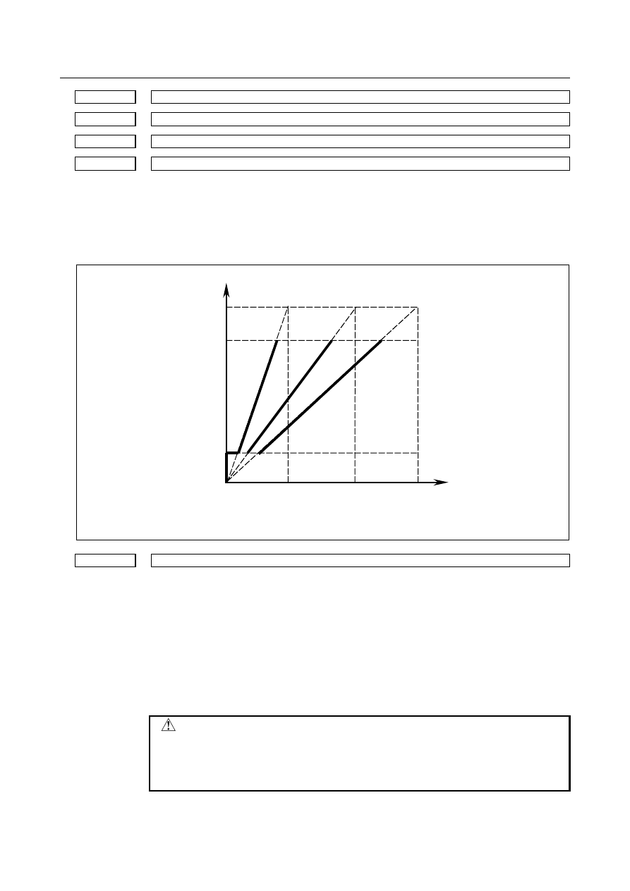
Set the maximum spindle speed corresponding to each gear. 


Spindle motor max. clamp speed   
(Parameter No.3736) 

Spindle speed command   
(S command) 

Max. speed (4095, 10V) 

Spindle motor minimum clamp speed   
(Parameter No.3735) 

Spindle motor speed 

Gear 1   
Max. speed 
(Parameter 
No.3741) 

Gear 2   
Max. speed 
(Parameter 
No.3742) 

Gear 3   
Max. speed 
(Parameter 
No.3743) 


3772 


Maximum spindle speed 


[Input type]  Parameter input 


[Data type]  2-word spindle 


[Unit of data]  min

-1


[Valid data range]  0 to 99999999 

This parameter sets the maximum spindle speed.   
When a command specifying a speed exceeding the maximum speed of the spindle is 
specified , or the speed of the spindle exceeds the maximum speed because of the spindle 
speed override function, the spindle speed is clamped at the maximum speed set in the 
parameter.   
 

  CAUTION 

1  When 0 is set in this parameter, the speed of the spindle is not 

clamped.   

2  When spindle speed command control is applied using the PMC, 

this parameter has no effect, and the spindle speed is not clamped.   


B-64693EN-1/01


10. SPINDLE SPEED FUNCTION


- 1619 - 

NOTE 

1  For M series, this parameter is valid if the function of constant 

surface speed control is enabled(bit 0(SSC) of parameter No.8133 
is 1). 

2  When the constant surface speed control is enabled, the spindle 

speed is clamped at the maximum speed, regardless of whether 
the G96 mode or G97 mode is specified. 


3775 


Default P command value for spindle selection in multi-spindle control 


NOTE 


When this parameter is set, the power must be turned off before 
operation is continued. 


[Input type]  Parameter input 


[Data type]  Word path 

[Valid data range]  0 to 32767 

When bit 3 (MPP) of parameter No. 3703 is set to 1 and bit 2 (MPA) of parameter No. 
3706 is set to 1 in multi-spindle control, set a default P command value applicable if S_P_ 
is not specified even once after power-up. 
 

3781 


P code for selecting the spindle in multi-spindle control 


[Input type]  Parameter input 


[Data type]  Word spindle 

[Valid data range]  0 to 32767 

If bit 3 (MPP) of parameter No. 3703 is set to 1, set the P code to select each spindle 
under multi-spindle control. Specify the P code in a block containing the S command. 


[Example]  If the P code value for selecting the second spindle is set to 2, 

S1000 P2; 
causes the second spindle to rotate at S1000. 
 

NOTE 

1  This parameter is valid if bit 3 (MPP) of parameter No. 3703 is set 

to 1. 

2  If this parameter is set to 0, the corresponding spindle cannot be 

selected by a P code. 

3  Under multi-path control, the P code specified here is valid for each 

path. 


For instance, if the P code to select the first spindle of path 2 is set 
to 21, specifying S1000 P21; in path 1 causes the first spindle of 
path 2 to be rotated at S1000. 

4  Identical P code values cannot be used for different spindles. 

(Identical P code values cannot be used even if the paths are 
different.) 

5  When this parameter is used (when bit 3 (MPP) of parameter No. 

3703 is set to 1), the spindle command selection signal is invalid. 

6  To use this parameter, enable the multi-spindle control function(bit 

1(MSP) of parameter No.8133 is 1). 


10. SPINDLE SPEED FUNCTION


B-64693EN-1/01


- 1620 - 


#7 

#6 

#5 

#4 

#3 

#2 

#1 

#0 

3786 


MPF 


[Input type]  Parameter input 


[Data type]  Bit 


NOTE 


When this parameter is set, the power must be turned off before 
operation is continued. 


#2  MPF

  When M03/M04/M05 is commanded by "M_P_" format in multi-spindle control, 

multi-spindle address P signal <Fn160-Fn161> is: 
0: 

Not output. 

1: 

Output. 


NOTE 


This parameter is valid when bit 3 (MPP) of parameter No.3703 is 
set to 1. 


#7 

#6 

#5 

#4 

#3 

#2 

#1 

#0 

3798 


ESN 


[Input type]  Parameter input 


[Data type]  Bit 


#1  ESN

  When the multi-spindle control is enabled and bit 3 (MPP) of parameter No. 3703 is set 

to 1, a spindle is specified in a program by using: 
0: 

P command. 

1: 

Extended spindle name. 

 
A spindle to be specified is selected as follows: 

Bit 1 (ESN) of 

parameter No. 3798 

Bit 3 (MPP) of 

parameter No. 3703 

Selection method 

Signal selection 

P command (S_P_) 

Signal selection 

Extended spindle name 

or 

P command (S_P_) 


NOTE 


This parameter is valid when bit 0 (EEA) of parameter No. 1000 is 
set to 1. 


When setting this parameter to 1, set also parameter No. 3738 and 
No. 3739 properly. 


11090 


Path number with which the rotation of each spindle is specified 


[Input type]  Parameter input 


[Data type]  Byte spindle 

[Valid data range]  0 to 10 

When a path is specified for spindle commands, this parameter sets a path number with 
which the rotation of a spindle can be specified. 
0: 

Spindle commands can be issued from all paths. 

B-64693EN-1/01


10. SPINDLE SPEED FUNCTION


- 1621 - 

1 to 10:  Spindle commands can be issued from a set path. 
 

NOTE 

1  This parameter is valid when spindle command path specification 

signal SPSP<Gn536.7> is set to "1". 

2  If the setting is illegal, an alarm PS5305, “ILLEGAL SPINDLE 

NUMBER” is issued when a spindle command is issued from any 
one of the paths. 

3  This setting does not apply to spindle commands using the spindle 

select signals SWS1 to SWS4<Gn027.0 to Gn027.2, Gn026.3>. 


Caution 

  CAUTION 

1  If the primary spindle stop signal *SSTP<Gn029.6> for stopping all selected 

(SWS1 to SWS4) spindles’ rotation is cleared, the speed command is restored.   


A spindle not selected by SWS1 to SWS4 and rotating at its previous speed, 
which is stopped using its respective command *SSTP1 to *SSTP4, cannot be 
restored to that speed when the signal is cleared. 

2  While a function using a position coder feedback such as feed per revolution and 

a threading command is being executed, avoid changing the selection of a 
position coder by using position coder selection signals PC2SLC<Gn028.7> , 
PC3SLC<Gn026.0> , and PC4SLC<Gn026.1> . 

3  Type A multi-spindle control differs from Type B in the relationship between the 

SWS1 and SIND signals for the first spindle. In Type A, SIND functions only when 
SWS1 is set to "1". In Type B, SIND functions whether SWS1 is "1" or "0"; each 
spindle is selected by either of its respective SWS1 or SIND signals being set to 
"1".   


Note 

NOTE 

1  The spindle orientation signal SOR<Gn029.5>, spindle speed override signals 

SOV0 to SOV7<Gn030>, and spindle stop signal *SSTP <Gn029.6> only 
function for the selected spindle. 

2  The multi-spindle control allows multiple position coder interfaces to be used. But 

the number of actual speed indications on the CNC screen does not change. 
The speed based on the feedback information of the selected position coder is 
displayed.   

3  An SOR command has priority over S commands and SIND-based rotation 

control from the PMC, and will cause all selected spindles to perform orientation 
rotation.   


Alarm and message 

Number 

Message 

Description 

PS0333 

TOO MANY SPINDLE 
COMMANDS 

Multiple spindle commands could be found in the same block in 
using an expansion spindle name. 
Only one spindle could be commanded in the same block.   

10. SPINDLE SPEED FUNCTION


B-64693EN-1/01


- 1622 - 

Number 

Message 

Description 

PS5305 

ILLEGAL SPINDLE NUMBER 

In a spindle select function by address P for a multiple spindle 
control, 
1  Address P is not specified. 
2  Parameter No. 3781 is not specified to the spindle to be 

selected. 

3  An illegal G code which cannot be commanded with an S_P_; 

command is specified. 

4  The multi-spindle control cannot be used because the bit 1 

(EMS) of parameter No. 3702 is 1. 

5  The spindle amplifier number of each spindle is not set in 

parameter No. 3717. 

6  A prohibited command for a spindle was issued (parameter 

No. 11090). 

7  An invalid value is set in parameter No. 11090. 

SP1202 

SPINDLE SELECT ERROR 

In the multi-spindle control, the spindle number other than the 
valid spindle number was selected by a position coder select 
signal. An attempt was made to select the spindle number of the 
system having no valid spindle. 


B-64693EN-1/01


10. SPINDLE SPEED FUNCTION


- 1623 - 

10.13 

RIGID TAPPING 

Overview 

In a tapping cycle (Machining center system: G84/G74, Lathe system: G84/G88), synchronous control is 
applied to the tapping operation of a tapping axis and the operation of the spindle. 
This capability eliminates the need to use a tool such as a float tapper, thus enabling higher-speed, 
higher-precision tapping. 
Whether a tapping cycle is an ordinary tapping cycle or rigid tapping cycle is determined by the 
miscellaneous function code for rigid tapping M29. (A different M code can be used by setting the 
parameters accordingly, but M29 is used in the description given here.) 
By setting the parameters, G codes for tapping cycles can be changed to G codes for rigid tapping only. In 
this case, the CNC specifies M29 internally. 
To perform rigid tapping, the following must be added to the ordinary connections: 

Connection of a position coder to the spindles 

Addition of a sequence to the PMC 

Setting of related parameters 

 
To avoid duplicate descriptions, assume the following unless noted otherwise: 
 

G code for a tapping cycle 

Machining center system 

Lathe system 

G84/G74 

G84/G88 


Gear selection method 

Machining center system 

Lathe system 

M-type or T-type gear selection method   

T-type gear selection method only 


Parameters used according to the number of gear stages 

No.5221 to No.5224, No.5231 to No.5234, No.5241 to No.5244, 
No.5261 to No.5264, No.5271 to No.5274, No.5281 to No.5284, 
No.5291 to No.5294, No.5321 to No.5324,etc. 


  CAUTION 

1  In the text of this section, a description of up to four-step gears is provided. 

Gears of four steps are used with the lathe system, but gears of up to only three 
steps are used with the machining center system. 

2  When M-type gear selection is used for the machining center system, the 

maximum spindle speed for rigid tapping (specified with parameters Nos. 5241 
to 5243) must also be set for parameter No. 5243 regardless of the number of 
gear steps. (For a system having a single gear step, set the same value as that 
of parameter No. 5241 for parameter No. 5243. For a system having two gear 
steps, set the same value as that of parameter No. 5242 for parameter No. 
5243.) 

 
The descriptions given in this section (such as spindle gear switching and M-type/T-type) are based on 
the explanation given in Section "SPINDLE SPEED CONTROL." 
Refer to Section "SPINDLE SPEED CONTROL" as necessary. 
 

  - 

Specification of machining center system/lathe system 

The differences in the specifications for rigid tapping for the machining center system and  lathe system 
are described below. 
 

10. SPINDLE SPEED FUNCTION


B-64693EN-1/01


- 1624 - 

M


  Rigid tapping of machining center system 

The tapping cycle G84 and the reverse tapping cycle G74 can be used to specify machining center system 
rigid tapping. 
A drilling axis can be arbitrarily selected from the basic axes X, Y, Z, as well as axes parallel to the basic 
axes, by setting the corresponding parameters accordingly (bit 0 (FXY) of parameter No. 5101). 
The spindle operations of G84 and G74 are reversed with respect to each other. 
 

T


  Rigid tapping of lathe system 

The face tapping cycle G84 and the side tapping cycle G88 can be used to specify lathe system  rigid 
tapping. 
Depending on the rigid tapping command, rigid tapping can be performed along the Z-axis (when G84 is 
used) or the X-axis (when G88 is used). 
A reverse tapping cycle, like that supported by machining center system, is not available. 


See "Rigid Tapping with Spindle of Another Path" for explanations about rigid tapping between different 
paths (rigid tapping on a spindle for tool post 2 as directed by a command for tool post 1) in a multi-path 
system. 
 

  - 

Multi-spindle control 

The relationships between rigid tapping and multi-spindle control are described below. 


  Without multi-spindle control 

Rigid tapping can be performed with the first spindle only. 


  With multi-spindle control 

Rigid tapping  can be performed  by selecting the second through fourth spindles in addition to the first 
spindle. 
 

10.13.1 

Connection Among Spindle, Spindle Motor, and Position 
Coder 

As shown in the figures (Fig. 10.13.1 (a) and Fig. 10.13.1 (b)) below a gear ratio can be inserted between 
the spindle and spindle motor (n : m), and between the spindle and position coder (N : M). 


Spindle control 

Spindle 
amplifier 

Spindle motor 

Spindle 

Gear ratio n:m 

Error counter 

Gear ratio N : M 

Position coder 

The number of pulses per position coder revolution is set in parameter No. 3720. 


Fig. 10.13.1 (a) When a position coder is externally attached (on the spindle side)


B-64693EN-1/01


10. SPINDLE SPEED FUNCTION


- 1625 - 


Spindle control 

Spindle 
amplifier 

Spindle motor 

Spindle 

Position coder 

Error counter 

Gear ratio  n : m 
 

N : M 

The number of pulses per position coder revolution is 
  set in parameter No. 3720. 


Fig. 10.13.1 (b) When a position coder is built into a spindle motor 


(1) Gear between spindle and spindle motor 

Up to three gear stages (machining center system) or four gear stages (lathe system) can be provided 
between the spindle and the spindle motor.   
The gear ratio is arbitrary.  The distance of spindle rotation per revolution of spindle motor is different, 
based on the gear ratio. The speed command to the spindle motor will be adjusted.   
 

(2) Gear between spindle and position coder 

The position coder is used to detect the position of the spindle. 
The gear ratio between the spindle and position coder is set in parameters Nos. 5221 to 5224 and 5231 to 
5234. 
When a position coder is externally attached, the gear ratio between the spindle and position coder is not 
changed by a gear change between the spindle  motor  and  spindle. So, set the same number  of teeth in 
parameters Nos. 5221 to 5224 and 5231 to 5234. 
When a position coder is built into a spindle motor, the gear ratio between the spindle and position coder 
is changed by a gear change between the spindle motor and spindle. So, set the number of teeth for each 
gear in parameters Nos. 5221 to 5224 and 5231 to 5234. 
Example of setting for the machining center system) 


Parameter No. 

Set value 

Meaning 

5221 

70 

Number of teeth of the 1st gear for the spindle side 

5222 

50 

Number of teeth of the 2nd gear for the spindle side 

5223 

30 

Number of teeth of the 3rd gear for the spindle side 

5231 

30 

Number of teeth of the 1st gear for the position coder side 


Content      ..     206      207      208      209     ..