FANUC Series 0i-MODEL F Plus. CONNECTION MANUAL (FUNCTION) - page 207
 

  Index      Manuals     FANUC Series 0i-MODEL F Plus. CONNECTION MANUAL (FUNCTION) B-64693EN-1/01


Search            copyright infringement  


Content      ..     205      206      207      208     ..


FANUC Series 0i-MODEL F Plus. CONNECTION MANUAL (FUNCTION) - page 207


10. SPINDLE SPEED FUNCTION


B-64693EN-1/01


- 1610 - 


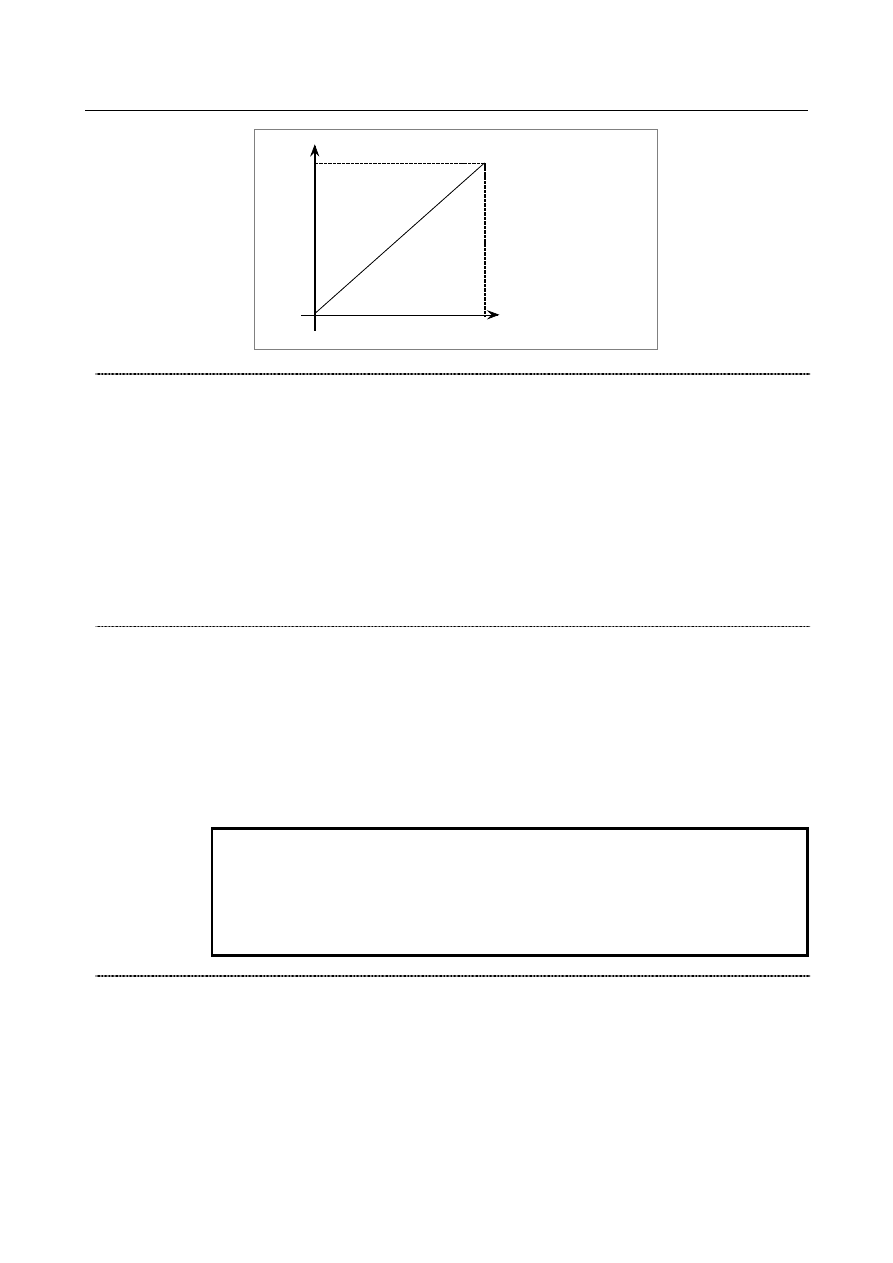
Code signal 

0 min

-1


4095 

Maximum speed 
of spindle motor 

(Spindle motor speed output) 


Address P signals MSP00 to MSP15<Fn160.0 to Fn161.7> 

  [Classification]  Output signal 
 

[Function]  The P value specified last by the S_P_; command is output. 

When extended spindle names are used, the value in parameter No. 3781 corresponding 
to the spindle number of the spindle name specified last is output. 


[Output cond.]  When multi-spindle control by using address P is enabled (bit 3 (MPP) of parameter No. 

3703 is 1), the P value specified in the S_P_; command is output. When no S_P_; 
command has been specified even once since power-up, the initial P value set in 
parameter No. 3775 is output. 
When extended spindle names are used, the value in parameter No. 3781 corresponding 
to the spindle number of the spindle name specified last is output. When no spindle name 
has been specified even once, the value set in parameter No. 3775 is output. 
 

1st spindle speed override signal SOV0 to SOV7<Gn030> 
2nd spindle speed override signal SOV20 to SOV27<Gn376> 
3rd spindle speed override signal SOV30 to SOV37<Gn377> 
4th spindle speed override signal SOV40 to SOV47<Gn378> 

  [Classification]  Input signal 
 

[Function]  If bit 4 (EOV) of parameter No.  3713  =  1, an override of 0% to 254%  of the rotation 

speed specified by the CNC can be applied to individual spindles separately. 


[Operation]  Specify an override value, using an 8-bit binary number. 


  If all bits are 1, however, an override of 0% is assumed. 


NOTE 


If bit 4 (EOV) of parameter No. 3713 = 0, the override signals 
SOV0 to SOV7 are applied to all spindles that receive speed 
commands. 
The signals SOV20 to SOV27, SOV30 to SOV37, and SOV40 to 
SOV47 are invalid. 


Spindle command path specification signal SPSP<Gn536.7> 

  [Classification]  Input signal 
 

[Function]  Turns spindle command path specification ON or OFF. 


[Operation]  If a command based on address P (bit 3 (MPP)  of parameter No. 3703  =  1  and bit 1 

(ESN) of parameter No. 3798 = 0) or a command based on an extended spindle name (bit 
3 (MPP) of parameter No. 3703  =  1,  bit 0 (EEA) of parameter No. 1000  =  1,  and bit 1 
(ESN) of parameter No. 3798 = 1) is used in multi-spindle control: 

B-64693EN-1/01


10. SPINDLE SPEED FUNCTION


- 1611 - 

Setting this signal to 1 enables path specification for spindle commands. 
Spindle commands can be issued from the path specified by parameter No. 11090. 
If  a spindle command is issued from a path other than the path, PS5305 alarm is 
issued. 

Setting this signal to 0 disables path specification for spindle commands. 


Spindle commands can be issued from individual paths no matter what the setting of 
parameter No. 11090. 


Signal address 


#7 

#6 

#5 

#4 

#3 

#2 

#1 

#0 

Gn026 


*SSTP4 


SWS4 


PC4SLC 

PC3SLC 


Gn027 


*SSTP3 

*SSTP2 

*SSTP1 

SWS3 

SWS2 

SWS1 


Gn028 


PC2SLC 


GR2 

GR1 


Gn029 


*SSTP 


GR32 

GR31 

GR22 

GR21 


Gn030 


SOV7 

SOV6 

SOV5 

SOV4 

SOV3 

SOV2 

SOV1 

SOV0 


Gn031 


GR42 

GR41 


Gn032 


R08I 

R07I 

R06I 

R05I 

R04I 

R03I 

R02I 

R01I 


Gn033 


SIND 

SSIN 

SGN 


R12I 

R11I 

R10I 

R09I 


Gn034 


R08I2 

R07I2 

R06I2 

R05I2 

R04I2 

R03I2 

R02I2 

R01I2 


Gn035 


SIND2 

SSIN2 

SGN2 


R12I2 

R11I2 

R10I2 

R09I2 


Gn036 


R08I3 

R07I3 

R06I3 

R05I3 

R04I3 

R03I3 

R02I3 

R01I3 


Gn037 


SIND3 

SSIN3 

SGN3 


R12I3 

R11I3 

R10I3 

R09I3 


Gn272 


R08I4 

R07I4 

R06I4 

R05I4 

R04I4 

R03I4 

R02I4 

R01I4 


Gn273 


SIND4 

SSIN4 

SGN4 


R12I4 

R11I4 

R10I4 

R09I4 


Gn376 


SOV27 

SOV26 

SOV25 

SOV24 

SOV23 

SOV22 

SOV21 

SOV20 


Gn377 


SOV37 

SOV36 

SOV35 

SOV34 

SOV33 

SOV32 

SOV31 

SOV30 


Gn378 


SOV47 

SOV46 

SOV45 

SOV44 

SOV43 

SOV42 

SOV41 

SOV40 


Gn536 


SPSP 


#7 

#6 

#5 

#4 

#3 

#2 

#1 

#0 

Fn001 


ENB 


Fn036 


R08O 

R07O 

R06O 

R05O 

R04O 

R03O 

R02O 

R01O 


Fn037 


R12O 

R11O 

R10O 

R09O 


Fn038 


ENB3 

ENB2 


Fn039 


ENB4 


Fn160 


MSP07 

MSP06 

MSP05 

MSP04 

MSP03 

MSP02 

MSP01 

MSP00 


Fn161 


MSP15 

MSP14 

MSP13 

MSP12 

MSP11 

MSP10 

MSP09 

MSP08 


Fn200 


R08O2 

R07O2 

R06O2 

R05O2 

R04O2 

R03O2 

R02O2 

R01O2 


10. SPINDLE SPEED FUNCTION


B-64693EN-1/01


- 1612 - 

Fn201 


R12O2 

R11O2 

R10O2 

R09O2 


Fn204 


R08O3 

R07O3 

R06O3 

R05O3 

R04O3 

R03O3 

R02O3 

R01O3 


Fn205 


R12O3 

R11O3 

R10O3 

R09O3 


Fn270 


R08O4 

R07O4 

R06O4 

R05O4 

R04O4 

R03O4 

R02O4 

R01O4 


Fn271 


R12O4 

R11O4 

R10O4 

R09O4 


Parameter 

Parameters related to the first spindle and first position coder are the same as those used conventionally. 
The following explains the parameters added in connection with this function and related parameters: 


#7 

#6 

#5 

#4 

#3 

#2 

#1 

#0 

1000 


EEA 


[Input type]  Parameter input 


[Data type]  Bit 


#0  EEA

  An extended axis name and extended spindle name are: 

0: 

Invalid 

1: 

Valid 


#7 

#6 

#5 

#4 

#3 

#2 

#1 

#0 

3106 


SOV 


[Input type]  Setting input 


[Data type]  Bit 


#5  SOV

  A spindle override value is: 

0: 

Not displayed. 

1: 

Displayed. 


NOTE 


This parameter is valid only when bit 2 (DPS) of parameter No. 
3105 is set to 1. 


#7 

#6 

#5 

#4 

#3 

#2 

#1 

#0 

3702 


EMS 


[Input type]  Parameter input 


[Data type]  Bit path 


#1  EMS

  The multi-spindle control is: 

0: 

Used. 

1: 

Not used.   


#7 

#6 

#5 

#4 

#3 

#2 

#1 

#0 

3703 


MPP 


[Input type]  Parameter input 


[Data type]  Bit 

B-64693EN-1/01


10. SPINDLE SPEED FUNCTION


- 1613 - 

NOTE 


When this parameter is set, the power must be turned off before 
operation is continued. 


#3  MPP

  In multi-spindle control, a spindle selection using a programmed  command instead of 

using the signals (SWS1 to SWS4<Gn027.0 to Gn027.2, Gn026.3>) is: 
0: 

Not made. 

1: 

Made. 


NOTE 


When this parameter is set to 1, set parameter No. 3781 at the same 
time. 


#7 

#6 

#5 

#4 

#3 

#2 

#1 

#0 

3706 


MPA 


GTT 


MPA 


[Input type]  Parameter input 


[Data type]  Bit path 


#2  MPA

  If a spindle is to be selected using a P command (with bit 3 (MPP) of parameter No. 3703 

set to 1) in multi-spindle control, and a P command is not specified together with an S 
command: 
0: 

The alarm PS5305, “ILLEGAL SPINDLE NUMBER” is issued. 

1: 

The last P specified by S_ P_; (by S_ P_; specified for the path in case of a 
multi-path system) is used. If P is not specified even once after power-up, the value 
of parameter No. 3775 is used. 


NOTE 


This parameter is valid only when bit 3 (MPP) of parameter No. 
3703 is set to 1. 


#4  GTT

  Spindle gear selection method is: 

0: 

Type M. 

1: 

Type T. 


NOTE 

1  This parameter is effected for M system. 
2  M type 
 

The gear selection signal is not input. The CNC selects a gear 
based on the speed range of each gear set by a parameter 
beforehand according to S codes, and the selected gear is posted 
by outputting the gear selection signal. Moreover, the spindle 
speed matching the gear selected by the output gear selection 
signal is output. 


T type 


The gear selection signal is input. The spindle speed matching the 
gear selected by this signal is output. 

3  When the constant surface speed control is enabled(bit 0(SSC) of 

parameter No.8133 is 1), type T is selected, regardless of whether 
this parameter is specified. 

10. SPINDLE SPEED FUNCTION


B-64693EN-1/01


- 1614 - 

NOTE 

4  When type T spindle gear switching is selected, the following 

parameters have no effect: 
No.3705#2(SGB), No.3751, No.3752,   
No.3705#1(GST), No.3705#3(SGT), No.3761, No.3762, 
No.3705#6(SFA), No.3735, No.3736 
On the other hand, parameter No. 3744 becomes usable. 

5  When multi spindle control is used, select to T type. 


#7 

#6 

#5 

#4 

#3 

#2 

#1 

#0 

3708 


TSO 

SOC 


[Input type]  Parameter input 


[Data type]  Bit path 


#5  SOC

  During constant surface speed control (G96 mode), the speed clamp by the maximum 

spindle speed clamp command (G92 S_; (G50 for G code system A of lathe system)) is 
carried out: 
0: 

Before spindle speed override. 

1: 

After spindle speed override. 

If this parameter is set to 0, the spindle  speed may exceed the maximum spindle speed 
(numeric value following S in G92 S_; (G50 for G code system A of lathe system)). 
If this parameter is set to 1, the spindle speed is limited to the maximum spindle speed. 
The spindle speed is limited to the upper limit of spindle speed specified in parameter No. 
3772, irrespective of the setting of this parameter. 


#6  TSO

  During a threading or tapping cycle, the spindle override is: 

0: 

Disabled (tied to 100%). 

1: 

Enabled. 


NOTE 


During rigid tapping, the override is tied to 100%, irrespective of the 
setting of this parameter. 


#7 

#6 

#5 

#4 

#3 

#2 

#1 

#0 

3709 


MRS 

MSI 


[Input type]  Parameter input 


[Data type]  Bit path 


#2  MSI

  In multi-spindle control, the SIND signal is valid   

0: 

Only when the first spindle is valid (SIND signal for the 2nd, 3rd spindle becomes 
ineffective) (TYPE-A) 

1: 

For each spindle irrespective of whether the spindle is selected (Each spindle has its 
own SIND signal). (TYPE-B) 


#3  MRS

  When the actual spindle speed signals and S 12-bit code signals are output in 

multi-spindle control: 
0: 

The signals common to the first spindle and second spindle are used, and the signals 
for the spindle selected by the spindle selection signal are output. 

1: 

The signals for the first spindle  and the signals for the second spindle are output 
separately. 


B-64693EN-1/01


10. SPINDLE SPEED FUNCTION


- 1615 - 


#7 

#6 

#5 

#4 

#3 

#2 

#1 

#0 

3713 


MPC 


EOV 

MSC 


[Input type]  Parameter input 


[Data type]  Bit 


NOTE 


When at least one of these parameters is set, the power must be 
turned off before operation is continued. 


#3  MSC

  Multi-spindle control TYPE-C is: 

0: 

Not used. 

1: 

Used. 


NOTE 


If parameter MSC and bit 2 (MSI) of parameter No. 3709 for 
multi-spindle control TYPE-B ) are set to 1 at the same time, 
multi-spindle control TYPE-C is enabled. 


#4  EOV

  Each spindle speed override is: 

0: 

Not used. 

1: 

Used. 


NOTE 


Multi-spindle control TYPE-C (bit 3 (MSC) of parameter No. 
3713=1) is necessary to use this function. 


#6  MPC

  When a spindle is selected with address P in a program during multi-spindle control (bit 3 

(MPP) of parameter No. 3703 is set to 1), position coder feedback used for thread cutting, 
feed per revolution, and so forth is: 
0: 

Not changed automatically according to the selected spindle. 

1: 

Changed automatically according to the selected spindle. 


NOTE 


Setting this parameter produces the same effects as when position 
coder select signals PC2SLC<Gn028.7>, PC3SLC<Gn026.0>, and 
PC4SLC<Gn026.1>, inter-path spindle feedback signals 
SLPCA<Gn064.2>, SLPCB<Gn064.3>, SLPCC<Gn403.4>, and 
SLPCD<Gn403.5> are set. 
At this time, even when an attempt to set these signals is made by 
a PMC ladder, these signal operations are ignored. 


3718 


Subscript for display of a serial spindle (main spindle) or analog spindle 


[Input type]  Parameter input 


[Data type]  Byte spindle 

[Valid data range]  0 to 122 

Set a subscript to be added to spindle speed display on a screen such as the position 
display screen. 
Used when the spindle switching function is not used, or used for the main spindle when 
the spindle switching function is used. 
 

10. SPINDLE SPEED FUNCTION


B-64693EN-1/01


- 1616 - 

NOTE 


This parameter is invalid when an extended spindle name is used. 


3719 


Subscript for display of a serial spindle (sub-spindle) 


[Input type]  Parameter input 


[Data type]  Byte spindle 

[Valid data range]  0 to 122 

Set a subscript to be added to spindle speed display on a screen such as the position 
display screen. 
Used for the sub-spindle when the spindle switching function is used. 
 

NOTE 


This parameter is invalid when an extended spindle name is used. 


3720 


Number of position coder pulses 


NOTE 


When this parameter is set, the power must be turned off before 
operation is continued. 


[Input type]  Parameter input 


[Data type]  2-word spindle 


[Unit of data]  Number of pulses 

[Valid data range]  Serial spindle 

  : 

0, 4096    When bit 7 (FBP) of parameter No.3716 is set to 1: 4096

×

2

^14


Spindle control with servo motor 
  : 

0, 4096    When bit 7 (FBP) of parameter No.3716 is set to 1: 4096

×

2

^14


Analog spindle 
  : 

0, 4096    When bit 7 (FBP) of parameter No.3716 is set to 1: from 0 to 400000 


Set the number of position coder pulses. 
In analog spindle, 4096 is set to parameter automatically if parameter No.3720 is set to 0 
or less. 
In serial spindle or spindle control with servo motor, the setting method is changed by 
setting of the bit 7 (FBP) of parameter No.3716. 

When the bit 7 (FBP) of parameter No.3716 is set to 0: 


4096 is set to parameter automatically if parameter No.3720 is set to 0 or less. 

When the bit 7 (FBP) of parameter No.3716 is set to 1: 


4096

×

2

^14

 is set to parameter automatically. 


3721 


Number of gear teeth on the position coder side 


[Input type]  Parameter input 


[Data type]  Word spindle 

[Valid data range]  0 to 9999 

Set the number of gear teeth on the position coder side in speed control (such as feed per 
revolution). 
 

3722 


Number of gear teeth on the spindle side 


[Input type]  Parameter input 


[Data type]  Word spindle 

B-64693EN-1/01


10. SPINDLE SPEED FUNCTION


- 1617 - 

[Valid data range]  0 to 9999 

Set the number of gear teeth on the spindle side in speed control (such as feed per 
revolution). 
 

  CAUTION 

1  Parameter No.3721 and No.3722 can not be used for thread 

cutting. 
If thread cutting was done by setting the any value on these 
parameters, the correct screw can't be cut. 
In the machine to do thread cutting, connect mechanically between 
the spindle and position coder by the gear ratio=1:1. And these 
parameters set the No.3721=0, No.3722=0. 
(It is the setting for the gear ratio 1:1.) 

2  Parameter No.3721 and No.3722 can not be used for Cs contour 

control. If Cs contour control was done by setting the any value on 
these parameters, spindle can’t move as commanded. In the 
machine to do Cs contour control, connect mechanically between 
the spindle and position coder by the gear ratio = 1:1. And these 
parameters set the No.3721=0, No.3722=0. (It is the setting for the 
gear ratio 1:1.) 


3738 


Spindle name 2 of each spindle 


3739 


Spindle name 3 of each spindle 


[Input type]  Parameter input 


[Data type]  Byte spindle 

[Valid data range]  48 to 57, 65 to 90 

The command for a spindle is basically "S". 
When all conditions below are satisfied, however, an extended spindle name can be used. 
An extended spindle name consists of up to three characters starting with "S" as the first 
spindle name. Thus, a command for a spindle can be specified. 

The serial (analog) spindle function is enabled. 

The multi-spindle control is enabled. 

Bit 0 (EEA) of parameter No. 1000 is set to 1. 

Bit 3 (MPP) of parameter No. 3703 is set to 1. 

Bit 1 (ESN) of parameter No. 3798 is set to 1. 

Bit 4 (GTT) of parameter No. 3706 is set to 1. (M series only) 

 
As spindle name 2 (parameter  No. 3738) and spindle name 3 (parameter  No. 3739), 
ASCII codes from 0 to 9 and A to Z can be arbitrary set. However, before spindle name 3 
for a spindle can be valid, spindle name 2 must be set for the spindle. Moreover, when a 
character from 0 to 9 is set as spindle name 2, do not set a character from A to Z as 
spindle name 3. 
 

NOTE 

1  When an extended spindle name is used, a subscript (for a main 

spindle (parameter No. 3718)) and a subscript (for a sub-spindle 
(parameter No. 3719)) are unusable. 

2  When the custom macro function is enabled, the same extended 

spindle name as a reserved word must not be used. Such an 
extended spindle name is regarded as a reserved word. 


Content      ..     205      206      207      208     ..