FANUC Series 0i-MODEL F Plus. CONNECTION MANUAL (FUNCTION) - page 105
 

  Index      Manuals     FANUC Series 0i-MODEL F Plus. CONNECTION MANUAL (FUNCTION) B-64693EN-1/01


Search            copyright infringement  


Content      ..     103      104      105      106     ..


FANUC Series 0i-MODEL F Plus. CONNECTION MANUAL (FUNCTION) - page 105


4. REFERENCE POSITION ESTABLISHMENT


B-64693EN-1/01


- 794 - 

An uncontinuous point of scale data 

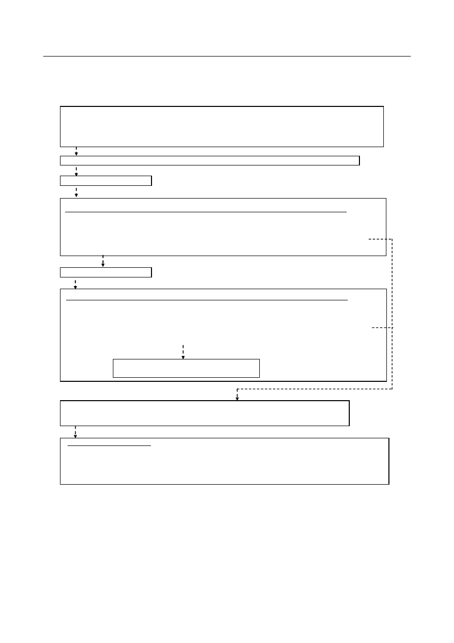
Before using this function, it is necessary to know the position of the uncontinuous point. By the 
following process, the position of the uncontinuous point can be found in the case of an absolute position 
detector (absolute pulse coder) (bit 5 (APC) of parameter No.1815=1). 


1. Perform a reference position return of the rotary axis with the parameter No.1817#3=0. 

 The correspondence between the reference position and position in   

   the absolute-position detector has been established. (parameter No.1815#4=1) 

2. Record machine coordinate value after moving the axis to one side of end of movable range. 

3. Turn the CNC off and on. 


 In the case that the machine coordinate value misses by the amount of one rotation : 

Go to the process 7 because an uncontinuous point of scale data exists within movable range. 

 In the case that the machine coordinate value does not miss and CNC starts normally : 


Record the machine coordinate value after moving to the other side of end of movable range. 

4. The machine coordinate value before and after the power supply turning on are compared. 

5. Turn the CNC off and on. 


 In the case that the machine coordinate value misses by the amount of one rotation : 

Go to the process 7 because an uncontinuous point of scale data exists within movable range. 

 In the case that the machine coordinate value does not miss and CNC starts normally : 

There is not an uncontinuous point within movable range. 

6. The machine coordinate value before and after the power supply turning on are compared. 

It is unnecessary to use this function. 

(No.1817#3=0) 


7. Record the machine coordinate value after moving by a constant interval (10 degree, for 

example) from present position for an inside of movable range. 


8. Turn the CNC off and on. 

 Until exceeding an uncontinuous point, the machine coordinate position is still different by 360 degree. 

 Until exceeding an uncontinuous point, repeat process 7 and 8. 

 After exceeding an uncontinuous point, the CNC starts on correct position. 

By the above process it is possible to know the approximate position of the uncontinuous point. 


In the case of the Fig. 4.12.2 (b) : 
1. 

A reference position return finishing. 

2. 

Moving the axis to one side of movable range (the machine coordinate value -45.000). 

3. 

Turnning the CNC off and on. 

4. 

Moving to the other side of movable range (the machine coordinate value is 45.000) because the 
machine coordinate value at power on is correct. 

5. 

Turnning the CNC off and on. 

6. 

Starting on -315.000 with the machine coordinate missing by 360 degree. 

7. 

Shifting to the inside direction by 10 degree and moving to the machine coordinate -325.000. 

8. 

Turnning the CNC off and on. 

B-64693EN-1/01


4. REFERENCE POSITION ESTABLISHMENT


- 795 - 

9. 

Starting correctly on the machine coordinate 35.000. 

 
Thus an uncontinuous point of scale data is found between 35.000 and 45.000. 
 

Parameter 


#7 

#6 

#5 

#4 

#3 

#2 

#1 

#0 

1815 


APCx 

APZx 


[Input type]  Parameter input 


[Data type]  Bit axis 


NOTE 


When at least one of these parameters is set, the power must be 
turned off before operation is continued. 


#4  APZx

  Machine position and position on absolute position detector when the absolute position 

detector is used   
0: 

Not corresponding 

1: 

Corresponding 

When an absolute position detector is used, after primary adjustment is performed or after 
the absolute position detector is replaced, this parameter must be set to 0, power must be 
turned off and on, then manual reference position return must be performed. This 
completes the positional correspondence between the machine position and the position 
on the absolute position detector, and sets this parameter to 1 automatically. 


#5  APCx

  Position detector 

0: 

Other than absolute position detector 

1: 

Absolute position detector (absolute Pulsecoder) 


NOTE 

1  In case of using FANUC absolute pulsecoder as absolute position 

detector for the rotary axis A type that machine coordinate values 
are rounded in 0 to 360°, set the parameter RON (No.1815#6) to 0. 
If the parameter is not set correctly, the machine coordinates are 
not correctly established at power-on. 

2  In case of using a rotary scale without rotary data made by another 

company as absolute position detector, please refer to 
"CORRESPONDENCE OF ROTARY SCALE WITHOUT ROTARY 
DATA" in the “CONNECTION MANUAL (FUNCTION)” 
(B-64693EN-1) and set an appropriate value corresponding to the 
detector. If the parameter is not set correctly, the machine 
coordinates are not correctly established at power-on. 

3  When the servo axis is disabled (bit 4 (KSVx) of parameter No. 

11802 is set to 1), an absolute position detector cannot be used (bit 
5 (APCx) of parameter No. 1815 cannot be set to 1). If an absolute 
position detector is used, alarm SV0301, "APC ALARM; 
COMMUNICATION ERROR" is issued. 


4. REFERENCE POSITION ESTABLISHMENT


B-64693EN-1/01


- 796 - 


#7 

#6 

#5 

#4 

#3 

#2 

#1 

#0 

1817 


SCRx 


[Input type]  Parameter input 


[Data type]  Bit axis 


NOTE 


When this parameter is set, the power must be turned off before 
operation is continued. 


#3  SCRx

  Specifies whether to convert scale data by using threshold position (parameter No. 1868) 

so that rotary axis B type is available, in the case of the axis B type that use a rotary scale 
without data (the number of rotation), whose movable range is under one rotation: 
0 :  Not to convert. 
1 :  To convert. 
 

NOTE 

1  This parameter is available for only the rotary axis B type with an 

absolute position detector (absolute Pulsecoder) or a rotary scale 
with distance-coded reference marks (serial). This function cannot 
be used for distance coded rotary scale interface (phase A/B). 

2  Don't set this parameter in the case of no uncontinuous point within 

movable range of rotary axis even if the rotary axis B type. 

3  When this parameter is set, machine position and position on 

absolute position detector become uncorresponding. So, establish 
the reference position again. (Consequently, the bit 4 (APZ) of 
parameter No. 1815 (indicating that the correspondence is 
established) is set to 0, and an alarm DS0300, "APC ALARM: 
NEED REF RETURN", occurs. Why the bit 4 (APZ) of parameter 
No. 1815 is set to 0 can be checked using diagnosis data No. 
310#0). 

4  This function cannot be used together with the bit 0 (RVSx) of 

parameter No. 1815 that save rotary data by CNC. 

5  In this function, the amount of one rotation of rotary axis assumes 

360, and the machine position 0 assumes the reference position. It 
is not possible to apply to a rotary axis other than the 
above-mentioned setting. 

6  Set the parameter No. 1240 to 0. 


1868 


Threshold position for converting scale data (each axis) 


NOTE 


When this parameter is set, the power must be turned off before 
operation is continued. 


[Input type]  Parameter input 


[Data type]  Real axis 


[Unit of data]  deg (machine unit) 

[Min. unit of data]  Depend on the increment system of the applied axis 
[Valid data range]  0 or positive 9 digit of minimum unit of data (Refer to the standard parameter setting 

table (B)) 
(When the increment system is IS-B, 0.0 to ++999999.999) 

B-64693EN-1/01


4. REFERENCE POSITION ESTABLISHMENT


- 797 - 

In the case that scale data of a rotary scale without rotary data is larger than the scale data 
of the threshold position (this parameter value), it is converted  to be continuous data in 
movable range by subtracting data of one rotation. The machine coordinate value out of 
movable range (angle from an uncontinuous point) must be set as threshold position. As 
for the axis for which this parameter is set to 0, conversion of scale data is not performed. 
 

NOTE 

1  This parameter is available for only the rotary axis B type with an 

absolute position detector (absolute Pulsecoder) or a rotary scale 
with distance-coded reference marks (serial), for which the bit 3 
(SCRx) of parameter No. 1817 is set to 1. 

2  This function cannot be used for distance coded rotary scale 

interface (phase A/B). 

3  Don't set this parameter in the case of no uncontinuous point within 

movable range of rotary axis even if the rotary axis B type. 

4  When this parameter is set, machine position and position on 

absolute position detector become uncorresponding. So, establish 
the reference position again. (Consequently, the bit 4 (APZ) of 
parameter No. 1815 (indicating that the correspondence is 
established) is set to 0, and an alarm DS0300, “APC ALARM: 
NEED REF RETURN”, occurs. Why the bit 4 (APZ) of parameter 
No. 1815 is set to 0 can be checked using diagnosis data No. 
0310#0). 


1869 


The amount of one rotation of rotary axis B type (each axis) 


NOTE 


When this parameter is set, the power must be turned off before 
operation is continued. 


[Input type]  Parameter input 


[Data type]  Real axis 


[Unit of data]  deg (machine unit) 

[Min. unit of data]  Depend on the increment system of the applied axis 
[Valid data range]  0 or positive 9 digit of minimum unit of data (Refer to the standard parameter setting 

table (B)) 
(When the increment system is IS-B, 0.0 to ++999999.999) 
Normally, the amount of one rotation of rotary axis is 360, and the machine position 0 is 
the reference position.   
In this case, this parameter is set to 0. 
 
For instance, when this parameter is set to 523.000, the amount of one rotation become 
523.000 (in the case of IS-B), if it is necessary to set it arbitrarily. 
 

NOTE 

1  This parameter is available for only the rotary axis B type with an 

absolute position detector (absolute Pulsecoder) or a rotary scale 
with distance-coded reference marks (serial), as for the bit 3 
(SCRx) of parameter No. 1817 is set to 1 or the bit 0 (RVS) of 
parameter No. 1815 is set to 1. 

4. REFERENCE POSITION ESTABLISHMENT


B-64693EN-1/01


- 798 - 

NOTE 

2  In the case that the amount of one rotation of rotary axis is 360, this 

parameter is set to 0.If it is necessary to set an amount of one 
rotation of rotary axis arbitrarily, this parameter is set to the amount 
of one rotation. 

3  When this parameter is set, machine position and position on 

absolute position detector become uncorresponding. So, establish 
the reference position again. (Consequently, the bit 4 (APZ) of 
parameter No. 1815 (indicating that the correspondence is 
established) is set to 0, and an alarm DS0300, “APC ALARM: 
NEED REF RETURN”, occurs. Why the bit 4 (APZ) of parameter 
No. 1815 is set to 0 can be checked using diagnosis data No. 
0310#0). 

4  This parameter No. 1869 is common in movable range that is 

under one rotation (the bit 3 (SCRx) of parameter No. 1817 is set to 
1) and movable range that is over one rotation (the bit 0 (RVS) of 
parameter No. 1815 is set to 1). 

5  Please set 0 to this parameter if the distance coded rotary scale 

interface (phase A/B) is used. 


4.12.3 

In the Case of a Rotary Axis B Type whose Movable Range is 
over One Rotation 

As for an axis whose movable range is over one rotation and its rotary scale which has no rotary data , for 
example, 30.000 degree and 390.000 degree have completely same scale data though their position is 
different from each other by just one rotation. It is possible to set rotary axis B type because CNC saves 
the rotary data by the following parameter even if in this case. 
As attention, a machine coordinate value may get  out over a rotation, in the case of moving over 180 
degree during turning off, because CNC saves a machine coordinate value just before CNC turns off and 
in following turning on get from the value. 
 

Parameter 


#7 

#6 

#5 

#4 

#3 

#2 

#1 

#0 

1815 


RVSx 


[Input type]  Parameter input 


[Data type]  Bit axis 


NOTE 


When this parameter is set, the power must be turned off before 
operation is continued. 


#0


RVSx

  When the scale without rotary data is used: 

0: 

The CNC does not maintain the rotary data. 

1: 

The CNC maintains the rotary data. 

This parameter is effective in the axis that satisfies either of the following conditions. 

The axis is rotary axis B type and the movable range is more than one rotation. 

The parameter RVL(No.11802#6)=1. 


B-64693EN-1/01


4. REFERENCE POSITION ESTABLISHMENT


- 799 - 

NOTE 

1  In the case of a rotary axis B type whose movable range is over 

one rotation, a rotary scale with rotary data had better be used. 
Otherwise, a machine coordinate value may get out over a 
rotation, in the case of moving over 180 degree during turning off. 

2  This parameter is available for the axis that is rotary axis B type or 

the axis whose bit 6 (RVLx) of parameter No.11802 is 1. This 
parameter is available for the axis with an absolute position 
detector (absolute Pulsecoder), a distance coded rotary scale 
interface (phase A/B) or a rotary scale with distance-coded 
reference marks (serial). 

3  If this parameter is available, the machine coordinate value just 

before CNC turns off is saved. In the case of moving over the 
following amounts during turning off or before reference position 
return, a machine coordinate value may get out over a rotation 
because CNC saves a machine coordinate value just before CNC 
turns off and in following turning on get from the value. 
In case of the rotary axis B type : 
 

Over 180 degree 

In case of the linear axis type : 
 

Over 1/4 of values set to parameter No.11810. 

4  If this parameter is changed, the correspondence between the 

machine position and the absolute position detector is lost. So, 
establish the reference position again. (Bit 4 (APZ) of parameter 
No.1815 is set to 0, and an alarm DS0300, “APC ALARM: NEED 
REF RETURN” is issued. The cause that sets bit 4 (APZ) of 
parameter No.1815 to 0 is indicated in diagnosis data No.310#0). 

5  Absolute coordinate value is set by machine coordinate value. 

However, after CNC turns on, the workpiece offset such as G92 
and G52 executed before CNC turns off is not set. 

6  This function cannot be used together with the bit 3 (SCRx) of 

parameter No. 1817 that convert scale data. 

7  In case of the rotary axis B type and the amount of one rotation of 

rotary axis is 360, set the parameter No.1869 to 0. Moreover, set 
the parameter No.1240 to 0 because the reference position must 
be 0 degree. 

8  In case of the rotary axis B type and the amount of one rotation of 

rotary axis is not 360, set the parameter No.1869 to the amount of 
one rotation. Moreover, set the parameter No.1240 to 0 because 
the reference position must be 0 degree. 

9  In case of the linear axis type, set the amount of the movement per 

one motor rotation to the parameter No.11810. 

10 This parameter cannot be used together with the stored stroke limit 

check immediately after power-on (parameter DOT(No.1311#0)). 


4. REFERENCE POSITION ESTABLISHMENT


B-64693EN-1/01


- 800 - 

1869 


The amount of one rotation of rotary axis B type (each axis) 


NOTE 


When this parameter is set, the power must be turned off before 
operation is continued. 


[Input type]  Parameter input 


[Data type]  Real axis 


[Unit of data]  deg (machine unit) 

[Min. unit of data]  Depend on the increment system of the applied axis 
[Valid data range]  0 or positive 9 digit of minimum unit of data (Refer to the standard parameter setting 

table (B)) 
(When the increment system is IS-B, 0.0 to ++999999.999) 
Normally, the amount of one rotation of rotary axis is 360, and the machine position 0 is 
the reference position.   
In this case, this parameter is set to 0. 
 
For instance, when this parameter is set to 523.000, the amount of one rotation become 
523.000 (in the case of IS-B), if it is necessary to set it arbitrarily. 
 

NOTE 

1  This parameter is available for only the rotary axis B type with an 

absolute position detector (absolute Pulsecoder) or a rotary scale 
with distance-coded reference marks (serial), as for the bit 3 
(SCRx) of parameter No. 1817 is set to 1 or the bit 0 (RVS) of 
parameter No. 1815 is set to 1. 

2  In the case that the amount of one rotation of rotary axis is 360, this 

parameter is set to 0.If it is necessary to set an amount of one 
rotation of rotary axis arbitrarily, this parameter is set to the amount 
of one rotation. 

3  When this parameter is set, machine position and position on 

absolute position detector become uncorresponding. So, establish 
the reference position again. (Consequently, the bit 4 (APZ) of 
parameter No. 1815 (indicating that the correspondence is 
established) is set to 0, and an alarm DS0300, “APC ALARM: 
NEED REF RETURN”, occurs. Why the bit 4 (APZ) of parameter 
No. 1815 is set to 0 can be checked using diagnosis data No. 
0310#0). 

4  This parameter No. 1869 is common in movable range that is 

under one rotation (the bit 3 (SCRx) of parameter No. 1817 is set to 
1) and movable range that is over one rotation (the bit 0 (RVS) of 
parameter No. 1815 is set to 1). 

5  Please set 0 to this parameter if the distance coded rotary scale 

interface (phase A/B) is used. 


4.12.4 

In the Case of a Rotary Axis A Type 

In the case of a rotary axis A type with an absolute position detector (absolute pulse coder), when the 
machine coordinate passes 0 degree or the shift value per one rotation (360 degree or the value of 
parameter No.1260), the data for the reference position (parameters Nos.1860 to 1862) is renewed so that 
following up at power on is within one rotation. But as for the absolute position detector (absolute pulse 

B-64693EN-1/01


4. REFERENCE POSITION ESTABLISHMENT


- 801 - 

coder) using a scale without rotary data, the data for the reference position (parameters Nos.1860 to 1862) 
need not be renewed because scale data without rotary data is always read at turning on. 
In this case, be sure to set the following parameters. 
 

Parameter 

1260 


The shift amount per one rotation of a rotary axis 


NOTE 


When this parameter is set, the power must be turned off before 
operation is continued. 


[Input type]  Parameter input 


[Data type]  Real axis 


[Unit of data]  deg 

[Min. unit of data]  Depend on the increment system of the applied axis 
[Valid data range]  0 or positive 9 digit of minimum unit of data (refer to the standard parameter setting table 

(B)) 
(When the increment system is IS-B, 0.0 to +999999.999) 
Set the shift amount per one rotation of a rotary axis. 
For the rotary axis used for cylindrical interpolation, set the standard value. 


#7 

#6 

#5 

#4 

#3 

#2 

#1 

#0 

1815 


RONx 


[Input type]  Parameter input 


[Data type]  Bit axis 


NOTE 


When this parameter is set, the power must be turned off before 
operation is continued. 


#6  RONx

  With a rotary axis A type, an absolute position detector (absolute Pulsecoder) using a 

scale without rotary data is: 
0: 

Not used. 

1: 

Used. 


NOTE 

1  This parameter is available for only the rotary axis A type with an 

absolute position detector (absolute Pulsecoder). This function 
cannot be used for a rotary scale with distance-coded reference 
marks (serial) or for a distance coded rotary scale interface (phase 
A/B). 

2  Set this parameter to 1 for the rotary axis A type using a rotary 

scale without rotary data such as HEIDENHAIN rotary scale RCN 
223F, 727F, etc. 


Set this parameter to 0


in any other case. If the parameter is not set 

correctly, the machine coordinates are not correctly established at 
power-on. 


Content      ..     103      104      105      106     ..