FANUC Series 0i-MODEL F Plus. CONNECTION MANUAL (FUNCTION) - page 86
 

  Index      Manuals     FANUC Series 0i-MODEL F Plus. CONNECTION MANUAL (FUNCTION) B-64693EN-1/01


Search            copyright infringement  


Content      ..     84      85      86      87     ..


FANUC Series 0i-MODEL F Plus. CONNECTION MANUAL (FUNCTION) - page 86


3. MANUAL OPERATION


B-64693EN-1/01


- 642 - 


Specified line


Approach direction


Direction of -

90

°


Direction of 

90

°


Specified line


Approach direction


Direction of 

90

°


Direction of -

90

°


<6>  Specify whether to enable the limit function. (Bit 7 of R975) 


To disable the limit function, set bit 7 of R975 to "0". 


To enable the limit function, set bit 7 of R975 to "1". 


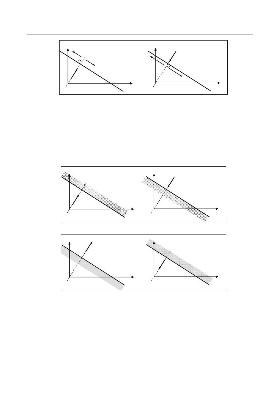
When the limit function is enabled, an area is set where the tool is not allowed to enter. The area is 
delimited with a specified line. When you attempt to bring the tool into the prohibited area, using 
manual handle feed or jog feed, the tool decelerates and  stops. Operation on the specified line is 
possible. 
The prohibited area is set as shown below, according to the setting of the approach direction (R962 
to R965, R966 to R969) and the setting of the prohibited area (Bit 6 of R975). 

 
- When bit 6 of R975 is set to "0" 


Specified line


Prohibited area


Approach direction


Specified line


Prohibited area


Approach direction


- When bit 6 of R975 is set to "1" 


Specified line


Prohibited area


Approach direction


Specified line


Prohibited area


Approach direction


<7>  Set the setting change notification. (R979) 
 

Set R979 to "0". 

 
This completes the straight line definition. 


During linear feed, the distance to the specified line is calculated, using the following equation, and 
output to R980 to R983 (4 bytes). 
The unit of the data is the least input increment for the reference axis. 
    F(X,Y) = p – ( Ix

X + Iy

Y ) 

    (Where X, Y = Current X- and Y-axis positions) 


B-64693EN-1/01


3. MANUAL OPERATION


- 643 - 

  - 

Setting for circular feed 

Specify the data according to the procedure below. 


CCW 

CW 

(X

0

, Y

0


Setting data 

<1> R961                : Circular feed and direction of rotation (CW/CCW) 

<2> R962 to R965 : Center of the circle X

0


<3> R966 to R969 : Center of the circle Y

0


<4> R970 to R973 : Radius R 

<5> R974                : Which side to be machined (inside or outside) 

<6> R975                : Whether the limit function is enabled or disabled 

<7> R979        : Setting change notification 

 
<1>  Specify circular feed and the direction of rotation. (R961) 
 

Set R961 to "2" or "3

".


If R961 is set to "2", the tool moves along the circle clockwise, when the guidance handle is rotated 
in the forward direction.   


If R961 is "3", the tool moves along the circle counterclockwise, when the guidance handle is 
rotated in the forward direction. 

 
<2> <3> Specify the coordinates (X

0

, Y

0

) of the center of the circle. (R962 to R965, R966 to R969) 


NOTE 


X and Y used in this description refer to coordinates in the absolute coordinate 
system. 


R962 to R965 = X

0


R966 to R969 = Y

0


Each coordinate is four bytes. The unit of the data is the least input increment for the reference axis. 

 
<4>  Specify radius R. (R970 to R973) 


R970 to R973 = R 


The radius R is four bytes. The unit of the data is the least input increment for the reference axis. 

 
<5> Specify which side is to be machined, the inside or outside of the circle. (R974) 
 

Set R974 to "0" or "1". 
 

If R974 is 0, the inside of the circle is machined. 


If R974 is 1, the outside of the circle is machined. 


When the approach handle is rotated, the tool moves along a straight line normal to the specified 
circle. The direction of the tool movement is determined according to the setting of R974.   

3. MANUAL OPERATION


B-64693EN-1/01


- 644 - 


When the approach handle is rotated in the forward direction, the direction of the tool movement 
(approach direction) is as follows: 


When the inside of the circle is to be machined (R974 = “0”), the tool moves from the center of 
the circle to the circumference. 


When the outside of the circle is to be machined (R974 = “1”), the tool moves toward the 
center of the circle. 


<6> Specify whether to enable or disable the limit function. (Bit 7 of R975) 


To disable the limit function, set bit 7 of R975 to 0. 


To enable the limit function, set bit 7 of R975 to 1. 


When the limit function is enabled, an area is set where the tool is not allowed to enter. The area is 
either inside or outside of the specified circle. When you attempt to bring the tool into the prohibited 
area, using manual handle feed or jog feed, the tool decelerates and stops. Operation on the specified 
circle is possible. 


Whether the inside or outside of the circle is set as the prohibited area is determined according to the 
setting of R974 that specifies which side (inside or outside of the circle) is to be machined and the 
setting of the prohibited area (Bit 6 of R975). 
- When bit 6 of R975 is set to "0" 

 Y 

Prohibited area


Approach direction 

<Inside to be machined> 

(R974 is “0”) 

Approach direction


<Outside to be machined> 

(R974 is “1”) 


Prohibited area


- When bit 6 of R975 is set to "1" 

 Y 

Prohibited area


Approach direction 

<Inside to be machined> 

(R974 is “0”) 

Approach direction


<Outside to be machined> 

(R974 is “1”) 

Prohibited area


<7> Set the setting change notification. (R979) 


Set R979 to "0". 

 
This completes the circle definition. 


During circular feed, the distance to the specified circle is calculated, using the following equation, 
and output to R980 to R983 (4 bytes). The unit of the data is the least input increment for the 
reference axis. 


When the inside of the circle is to be machined: 


F(X,Y) = R  –  

√ (X – X

0

)

2

 + (Y – Y

0

)

2


When the outside of the circle is to be machined: 


F(X,Y) =√ (X – X

0

)

2

 + (Y – Y

0

)

2

  –  R 


  - 

When neither linear nor circular feed is carried out 

Specify the following data. 
 

B-64693EN-1/01


3. MANUAL OPERATION


- 645 - 

Setting data 

<1> R961                : 0 (Neither linear nor circular feed is carried out) 

<2> R962 to R965 : (Need not be specified) 

<3> R966 to R969 : (Need not be specified) 

<4> R970 to R973 : (Need not be specified) 

<5> R974        : (Need not be specified) 

<6> R975        : (Need not be specified) 

<7> R976        : (Need not be specified) 

<8> R979        : Setting change notification 

 
<1>  Linear or circular feed selection 
 

Reset R961 to "0". 


If R961 is set to 0, both the guidance and approach handles become ineffective. 


The tool will not move, even if these handles are rotated. 

 
<2> to <7> It is unnecessary to set R962 to R976. 
 
<8>  Set the setting change notification. (R979) 
 

Set R979 to "0". 


The values of R980 to R983 (distance to a given line or circle) are output as "0". 


  - 

Manual handle feed 

In manual handle feed, the tool can be moved along a specified axis (X-axis, Y-axis, Z-axis, or N

th

-axis), 

along a rotated straight line (linear feed), or along a circle (circular feed). 
 
(1)  Feed along a specified axis (simultaneous 1-axis control) 
 

A single manual handle operation can move the tool along the desired axis, such as X-axis, Y-axis, 
or Z-axis, on a simultaneous 1-axis control basis. 

  Y 

Path of travel using the Y-axis handle


Path of travel using the X-axis handle


Feed along a specified axis 

 
(2)  Linear feed (simultaneous 2-axis control) 
 

A single manual handle operation can move the tool in parallel to the straight line on a simultaneous 
2-axis control basis. This manual handle is referred to as the "guidance handle". Also, the tool can be 
moved at right angles to a specified straight line on a simultaneous 2-axis control basis. This manual 
handle is referred to as the "approach handle". When the guidance handle or approach handle is 
turned clockwise or counterclockwise, the tool travels forward or backward along the respective 
path. 

3. MANUAL OPERATION


B-64693EN-1/01


- 646 - 


Path of travel using the 

approach handle 

Path of travel using the 

guidance handle 

Specified straight line


Tool 


Linear feed 


(3)  Circular feed (simultaneous 2-axis control) 
 

A single manual handle operation can move the tool from the current position along a concentric 
circle that has the same center as a specified circle on a simultaneous 2-axis control basis. This 
manual handle is referred to as the guidance handle. Also, a single manual handle operation can 
move the tool along a straight line normal to a specified circle on simultaneous 2-axis control. This 
manual handle is referred to as the approach handle. When the guidance handle or approach handle 
is turned clockwise or counterclockwise, the tool travels forward or backward along the respective 
path. 


Specified circle


Path of travel using the 
guidance handle


Path of travel using the 
approach handle 


Tool 


Circular feed 


  - 

Feedrate for manual handle feed 

The feedrate depends on the speed at which a manual handle is turned. The distance to be traveled by the 
tool (along a tangent in the case of linear or circular feed) per manual handle pulse can be selected using 
the manual handle feed travel distance magnification signal MP1<Gn019.4> or MP2<Gn019.5>. 
The approach handle clamp feedrate can be set using parameter No. 7160. The guidance handle clamp 
feedrate can be set using parameter No. 7161. Set the parameter No. 7117 to 0. 
 

  - 

Manual handle selection 

Five manual pulse generator interfaces are provided to allow up to five manual handles to be connected. 
The mode of the manual handles connected to the interfaces (whether to use the manual handle as a 
handle for feed along an axis, as a guidance handle, or as an approach handle) can be selected by the 
manual linear/circular interpolation signal MHLCn<Gn544.0 to Gn544.4>  and manual handle usage 
selection signal MHUSn<Gn545.0 to  Gn545.4>, which are provided for each interface. By switching 
these signals, a single manual handle can be used for multiple purposes. 
 

B-64693EN-1/01


3. MANUAL OPERATION


- 647 - 

  - 

Direction of movement using manual handles 

When the tool is moved along a straight line or circle using the guidance handle or approach handle, the 
direction of the tool movement (for example, whether to make a clockwise or counterclockwise 
movement along a circle) when the handle is turned clockwise or counterclockwise can be specified using 
the interfaces described above. 
 

  - 

Jog feed 

In jog feed, the tool can be moved along a specified axis (X-axis, Y-axis, Z-axis, etc.), along a rotated 
straight line (linear feed), or along a circle (circular feed). 
 
(1)  Feed along a specified axis (simultaneous 1-axis control) 
 

While a feed axis and its direction are specified with the feed axis direction selection signals 
+J1~+J8 <Gn100> and -J1~-J8 <Gn102>, the tool moves in the specified axis direction. 


When feeding the axis of selected plane (R976) of manual linear/circular interpolation in each axis 
direction, feedrate is the value of parameter No.1410 (parameter No.1415 is used when bit 4 (JRV) 
of parameter No.1402 is set to 1). The feedrate can be overridden (0.01% to 655.34%) using the 
manual feedrate override signal *JV0 to *JV15 <Gn010,Gn011>. 


NOTE 

1  Two axes of the selected plane cannot be fed at the same time in each axis 

direction. (When feed axis direction selection signals of two axes are set to "1" 
simultaneously, the two axes decelerate and stop.) 

2  The manual rapid traverse selection signal RT <Gn019.7> is invalid for two 

axes of selected plane. (Even if RT is set to "1", a rapid traverse rate is not 
selected.) 


When the axis excluding the plane axis selected by R976 of manual linear/circular interpolation is 
fed  in each axis direction, the feederate  is the value of parameter No. 1423. The feedrate can be 
overridden (0.01% to 655.34%) using the manual feedrate override signal *JV0~*JV15 <Gn010, 
Gn011>. 

 
(2)  Linear feed (simultaneous 2-axis control) 
 

By defining a straight line, the tool can be moved as follows: 

While a feed axis and its direction are selected using the feed axis direction selection signal 
+Jg<Gn086.0> or –Jg<Gn086.1>, the tool moves along a straight line parallel to the specified 
straight line on a simultaneous 2-axis control basis. 

While a feed axis and its direction are selected using the feed axis direction selection signal 
+Ja<Gn086.2>  or  -Ja<Gn086.3>, the tool moves along a straight line perpendicular to the 
specified straight line on a simultaneous 2-axis control basis. 


The feedrate in the tangential direction is specified in parameter No. 1410  (Parameter No.1415 is 
used when bit 4 (JRV) of parameter No. 1402 is set to 1). The feedrate can be overridden (0.01% to 
655.34%) using the manual feedrate override signal *JV0 to *JV15 <Gn010, Gn011>. The manual 
rapid traverse selection signal RT<Gn019.7>  is invalid.  (Even if RT is set to "1", a rapid traverse 
rate is not selected.) 

 
(3)  Circular feed (simultaneous 2-axis control) 
 

By defining a circle, the tool can be moved as follows: 

While a feed axis and its direction are selected using the feed axis direction selection signal 
+Jg<Gn086.0> or –Jg<Gn086.1>, the tool moves from the current position along the concentric 
circle that has the same center as the specified circle. 

While a feed axis and its direction are selected using the feed axis direction selection signal 
+Ja<Gn086.2>  or  -Ja<Gn086.3>, the tool moves along a straight line normal to the specified 
circle. 

3. MANUAL OPERATION


B-64693EN-1/01


- 648 - 


The feedrate in the tangential direction is specified in parameter No. 1410  (Parameter No.1415 is 
used when bit 4 (JRV) of parameter No. 1402 is set to 1). The feedrate can be overridden (0.01% to 
655.34%) using the manual feedrate override signal *JV0 to *JV15<Gn010,  Gn011>. The manual 
rapid traverse selection signal RT<Gn019.7>  is invalid.  (Even if RT is set to "1", a rapid traverse 
rate is not selected.) 


  - 

Manual handle feed in JOG mode 

Even in JOG mode, manual handle feed can be enabled using bit 0 (JHD) of parameter No. 7100. In this 
case, however, manual handle feed is enabled only when the tool is not moved using jog feed. 
 

Basic procedure 

(1)  Select the manual operation mode. 

To perform manual handle feed, select manual handle feed mode. To perform jog feed, select jog 
feed mode. 

(2)  Define a line or circle. 

See the "Line/circle definition" in the Explanations section. 

(3)  Move the tool using manual handle feed or jog feed. 


To perform the manual handle feed 


First, select either single-axis feed along the X-, Y-  or Z-axis, or simultaneous two-axis feed 
along a specified line or circle in the specified plane, using manual linear/circular interpolation 
signal MHLCn. 


To execute single-axis feed along the X-, Y- or Z-axis, select the axis along which the tool will 
move when  the manual handle is turned, using the manual handle feed axis selection signals 
HSnA, HSnB, HSnC, HSnD, and HSnE. 


To execute simultaneous two-axis feed in the specified plane, select either approach handle or 
guidance handle, using the manual handle usage selection signal (MHUSn). By selecting the 
plane, the two axes along which the tool will move when the manual handle is turned are 
selected. 


Turning the manual handle will move the tool along the selected axis. The feedrate varies with 
the speed at which the manual handle is turned. 


The amount the tool will be moved when the manual handle is turned by one pulse can be 
specified using manual handle feed amount selection signals MP1 and MP2. 

 
To perform the jog feed 
 

Select the feed axis and the direction in which the tool is to be moved, using the feed axis and 
direction selection signals +Jg, -Jg, +Ja, -Ja. While the feed axis is specified, the tool is moved 
along the specified axis or specified line or circle at the parameter-set feedrate (jog feedrate). 


The manual feedrate override signals *JV0 to *JV15 can be used to apply an override to the 
feedrate. The manual rapid traverse selection signal RT is invalid. 

 
To stop the feed of manual linear/circular interpolation 
 

When jog feed is performed without  carrying out the feed of manual linear/circular 
interpolation, specify the following data. 


-  Specify the R area in the PMC which is describe in the above-mentioned "When neither 
 

linear nor circular feed is carried out" 


-  Set Feed axis and direction selection signal +Jg, -Jg, +Ja, -Ja to “0” 


-  Set Manual linear/circular interpolation signal MHLC1 to MHLC5 to “0” 


Limitations 

  - 

Mirror image 

The mirror image function is not available during the manual operation. (Operate when the mirror image 
signal MI1 to MI3<Fn108> is set to "0" and the mirror image setting is off.) 
 

B-64693EN-1/01


3. MANUAL OPERATION


- 649 - 

NOTE 


If the tool is operated with the mirror image function activated, the normal 
operation will not be guaranteed. 


  - 

Rotation direction 

When this function is effective, bit 0 (HNGx) of parameter No. 7102 is invalid which is used to change 
the axis movement direction with respect to the rotation direction of the manual pulse generator. (The 
rotation direction of the manual pulse generator is always the same as the axis movement direction; that is, 
the operation is the same as when bit 0 (HNGx) of parameter No. 7102 is set to 0.) 
 

  - 

The amount of the shift for manual handle feed 

When this function is effective, parameters No. 12350 and No. 12351 used to determine the magnification 
of manual handle feed for each axis are invalid and the values of parameter No. 7113 and No. 7114 are 
used. (Parameters No. 7131 and No. 7132 are used for the second manual pulse generator, parameters No. 
7133 and No. 7134 for the third, parameters No. 7135 and No. 7136 for the fourth, and parameters No. 
7137 and No. 7138 for fifth.) 
 

  - 

Incremental feed 

This function is invalid for the incremental feed. 
 

  - 

Synchronous/composite control 

If the axis is set as the synchronous/composite control axis, this function is invalid. 
 

Note 

NOTE 

    When using this function, please enable "Manual handle feed (bit 0 (HPG) of 

parameter No.8131 is 1)". When using the fourth or fifth manual pulse generator, 
the function "Manual handle feed 4/5-unit" is needed. 


Signal 

The following signals are related to jog feed and manual handle feed. 
 

Feed axis and direction selection signal +Jg, -Jg, +Ja, -Ja <Gn086.0 to Gn086.3> 

  [Classification]  Input signal 
 

[Function]  Selects a desired feed axis and direction in jog feed. The sign (+ or -) in the signal name 

indicates the feed direction. "g" and "a" after J indicates Guidance JOG and Approach 
JOG, respectively. 


[Operation]  For operation, these signals are the same as feed axis and direction selection signal +J1 to 

+J8, -J1 to –J8 <Gn100, Gn102>. 
Refer to section "JOG FEED/ INCREMENTAL FEED". 


Manual linear/circular interpolation signal MHLC1 to MHLC5 <Gn544.0 to Gn544.4> 


[Classification]  Input signal 


[Function]  Each of these signals selects the manual linear/circular interpolation function for the n-th 

manual pulse generator. 


[Operation]  0: 

Manual linear/circular interpolation is disabled. The manual handle is used for axis 


direction feed. 

1: 

Manual linear/circular interpolation is enabled. The manual handle is used for the 
purpose selected by the usage selection of manual linear/circular interpolation signal 
(MHUSn). 


Content      ..     84      85      86      87     ..