FANUC Series 0i-MODEL F Plus. CONNECTION MANUAL (FUNCTION) - page 22
 

  Index      Manuals     FANUC Series 0i-MODEL F Plus. CONNECTION MANUAL (FUNCTION) B-64693EN-1/01


Search            copyright infringement  


Content      ..     20      21      22      23     ..


FANUC Series 0i-MODEL F Plus. CONNECTION MANUAL (FUNCTION) - page 22


1. AXIS CONTROL


B-64693EN-1/01


- 130 - 

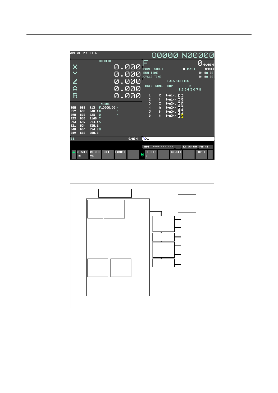
<1>  On the axis setting screen, enter 1 in M1 for the X-axis, 2 in M2 for the Y-axis, 1 in M2 for the 

Z-axis, 2 in M1 for the B-axis, and 3 in M2 for the C-axis. 


<2>  Press the soft key [SETTING] to perform FSSB automatic setting. 


  -  Example 3    Cs contour control 


X


Y


Z


B


Axis


1


X


2


Y


3


Z


4


A  (Cs contour 

controlled axis)


5


B


CNC


SV(2 axes)


SV(2 axes)


SV: Servo amplifier 

SP: Spindle amplifier


Controlled 

axis 

number 

Program 

axis name 

No.1020


SP


SP


S1


S2


Spindle 

number


1


2


Spindle 

name


S1 (Cs contour 

controlled axis)


S2


Fig. 1.4.3.2 (g) Setting example (Cs contour control) 


B-64693EN-1/01


1. AXIS CONTROL


- 131 - 

<1>  On the servo amplifier setting screen, enter 1, 2, 3, and 5 for AXIS. 


<2>  On the spindle amplifier setting screen, enter 1 and 2 for SP NUM. 


1. AXIS CONTROL


B-64693EN-1/01


- 132 - 

<3>  On the axis setting screen, enter 1 in Cs for the A-axis. 


<4>  Press the soft key [SETTING] to perform FSSB automatic setting. 


  -  Example 4  Tandem control 


X


A


Y


B


Z


C


Axis


1


X (tandem master)


2


Y


3


Z


4


A (tandem slave)


5


B


6


C


CNC


SV(2 axes)


SV(2 axes)


Controlled 

axis 

number 

Program 

axis name 

No.1020


SV(2 axes)


SV: Servo amplifier


Fig. 1.4.3.2 (h) Setting example (tandem control) 


B-64693EN-1/01


1. AXIS CONTROL


- 133 - 

<1>  On the servo amplifier setting screen, enter 1, 4, 2, 5, 3, and 6 for AXIS. 


<2>  On the axis setting screen, enter 1 in M/S for the X-axis and 2 in M/S for the A-axis. 


<3>  Press the soft key [SETTING] to perform FSSB automatic setting. 


1. AXIS CONTROL


B-64693EN-1/01


- 134 - 

  -  Example 5    Electronic gear box 


X 

Y 

Z 

A 

Axis 


1 

X (EGB slave) 

2 

Y 

3 

Z 

4 

A 

5 

B (EGB dummy) 

Controlled 

axis 

number 

Program axis 

name 

No.1020


CNC 

SV(2 axes) 

SV(2 axes) 

SV: Servo amplifier


Fig. 1.4.3.2 (i) Setting example (electronic gear box) 


<1>  For the X- and B-axes, set bit 0 (SYN) of parameter No. 2011 to 1. 

<2>  On the servo amplifier setting screen, enter 1, 2, 3, and 4 for AXIS. 


B-64693EN-1/01


1. AXIS CONTROL


- 135 - 

<3>  On the axis setting screen, enter 1 in M/S for the X-axis and 2 in M/S for the B-axis. 


<4>  Press the soft key [SETTING] to perform FSSB automatic setting. 


Parameter 

1023 


Number of the servo axis for each axis 


NOTE 

  When this parameter is set, the power must be turned off before 

operation is continued. 


[Input type]  Parameter input 


[Data type]  Byte axis 

[Valid data range]  0 to 78 

This parameter associates each control axis with a specific servo axis. Usually, set the 

same number as a controlled axis number and its corresponding servo axis number. 

The control axis number is the order number that is used for setting the axis-type 

parameters or axis-type machine signals 

Any multiple of 8 and the value obtained by subtracting 1 from a multiple of 8 cannot be 

set, however. When the number of controlled axes is 7 or more, set numbers with 

skipping any multiple of 8 and the value obtained by subtracting 1 from a multiple of 8. 


•


Example of setting when the number of controlled axes is 6 or less 

Parameter No.1023 

Setting value 

(1st axis) 

1 

(2nd axis) 

2 

(2rd axis) 

3 

(4th axis) 

4 

(5th axis) 

5 

(6th axis) 

6 


1. AXIS CONTROL


B-64693EN-1/01


- 136 - 

•


Example of setting when the number of controlled axes is 7 or more 

Parameter No.1023 

Setting value 

(1st axis) 

1 

(2nd axis) 

2 

(2rd axis) 

3 

(4th axis) 

4 

(5th axis) 

5 

(6th axis) 

6 

(7th axis) 

9 

(8th axis) 

10 

(9th axis) 

11 

(10th axis) 

12 

(11th axis) 

13 

(12th axis) 

14 

(13th axis) 

17 

(14th axis) 

18 


•


With an axis for which Cs contour control/spindle positioning is to be performed, set 

-(spindle number) as the servo axis number. 

Example) 

When exercising Cs contour control on the fourth controlled axis by using the 

first spindle, set -1. 

•


For tandem controlled axes or electronic gear box (EGB) controlled axes, two axes 

need to be specified as one pair. So, make a setting as described below. 

Tandem axis: For a master axis, set an odd (1, 3, 5, ...) servo axis number. For a 

slave axis to be paired, set a value obtained by adding 1 to the value 

set for the master axis. 

EGB axis:  For a slave axis, set an odd (1, 3, 5, ...)  servo axis number. For a 

dummy axis to be paired, set a value obtained by adding 1 to the value 

set for the slave axis. 


#7 

#6 

#5 

#4 

#3 

#2 

#1 

#0 

1902 


ASE 

FMD 


[Input type]  Parameter input 


[Data type]  Bit 


NOTE 

  When at least one of these parameters is set, the power must be 

turned off before operation is continued. 


#0  FMD

  The FSSB setting mode is: 

0:  Automatic setting mode. 

(When the relationship between an axis and amplifier is defined on the FSSB setting 

screen, parameters Nos. 1023, 2013#0, 2014#0, 3717, 11802#4, 24000 to 24103 are 

automatically set. 

1:  Manual setting 2 mode. 

(Parameters Nos. 1023, 2013#0, 2014#0, 3717, 11802#4, 24000 to 24103 are to be 

manually set.) 


#1  ASE

  When automatic setting mode is selected for FSSB setting (when the bit 0 (FMD) 

parameter No. 1902 is set to 0), automatic setting is: 

0:  Not completed. 

1:  Completed. 

B-64693EN-1/01


1. AXIS CONTROL


- 137 - 

This bit is automatically set to 1 upon the completion of automatic setting. 


#7 

#6 

#5 

#4 

#3 

#2 

#1 

#0 

3716 


A/Ss 


[Input type]  Parameter input 


[Data type]  Bit spindle 


NOTE 

  When this parameter is set, the power must be turned off before 

operation is continued. 


#0  A/Ss

  Spindle motor type is : 

0:  Analog spindle. 

1:  Serial spindle. 


NOTE 

1  When FSSB setting is used, the setting of serial spindle is required. 

2  When a serial spindle is used, enable the spindle serial output (bit 5 

(SSN) of parameter No.8133 is 0). 


3717 


Spindle amplifier number of each spindle 


NOTE 

  When this parameter is set, the power must be turned off before 

operation is continued. 


[Input type]  Parameter input 


[Data type]  Byte spindle 

[Valid data range]  0 to Maximum number of controlled axes 

Set a spindle amplifier number to be assigned to each spindle. 

0:  No spindle amplifier is connected. 

1:  Spindle motor connected to amplifier number 1 is used. 

2:  Spindle motor connected to amplifier number 2 is used. 

to 

n:  Spindle motor connected to amplifier number n is used. 


Content      ..     20      21      22      23     ..