Kawasaki Robot Controller F Series. Installation and Connection Manual (2016) - page 4
 

  Index      Manuals     Kawasaki Robot Controller F Series. Installation and Connection Manual (2016)


Search            copyright infringement  


Content      ..     2      3      4     


Kawasaki Robot Controller F Series. Installation and Connection Manual (2016) - page 4


F Series Controller 

6 Connection Instructions 

Kawasaki Robot  Installation and Connection Manual 

44 


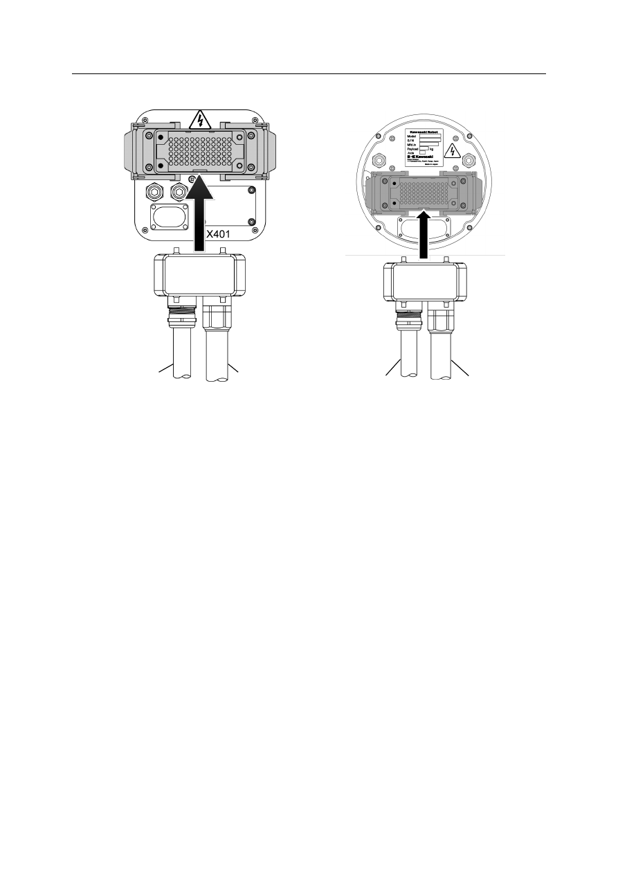
MC (Backside connector spec.


MC/MS (Base connector spec.) 


Signal harness 

Motor harness 

Signal harness 

Motor harness 

F Series Controller 

6 Connection Instructions 

Kawasaki Robot  Installation and Connection Manual 

45 

6.2  Connection between Controller and TP 

Connect the TP cable to the controller. 
 
1.  Insert the TP cable to the connector (XTP). 
2.  Turn right/left hand-cranked screws in a clockwise direction, and lock them securely. 


3.  In case of the sealed specification, read the precautions for connecting the harnesses for 

the sealed chassis controller given in “6.1 Connection between Controller and Robot” 
carefully before connecting the cables. 


CAUTION 


1.  If the hand-cranked screws on the right and left side of the XTP 

connector are loose, a TP screen display error or other failure can 
result. 

2.  Do not attempt to insert or pull out the XTP connector when it is alive. 

Damage to the board can result. 

Hand-cranked screw 

F Series Controller 

7 Connection of External Power 

Kawasaki Robot  Installation and Connection Manual 

46 

7  Connection of External Power 

Strictly observe the following precautions when connecting the external power. 


1.  Before connecting the external power, confirm that the external power 

supply for the controller is cut off at the source. Connecting 
components while power is supplied may cause electric shock. 

2.  To prevent external power from being turned ON accidentally, tag the 

breaker and indicate clearly that work is in progress. Or, assign a 
supervisor in front of the breaker until the connection is complete. 

DANGER 

WARNING 

1.  Confirm that the connected supplying power to the controller meets 

specifications shown on the rating plate. Supplying 
out-of-specification power will damage electric components in the 
controller. 

2.  Ground the controller to prevent against electrical shock and noise 

without fail. 
(1)  Dedicated ground: 

100 

 or less 

(2)  Recommended power cable size: ground wire which is 2.0 mm

2

 or 

more (AWG #14 or more) 

3.  Never share a ground line with workpiece to be welded or another 

machine (weld machine, etc.). 

4.  Strictly observe the following precautions when conducting the arc 

welding. 
(1)  Connect the minus pole of the weld power supply to a jig or 

directly to workpiece to be welded. 

(2)  Insulate the robot body and controller so that they do not share a 

common ground line. 

5.  Before turning ON the external power to controller, make sure the 

power supply wiring is complete and all the covers are attached 
properly. Failure to do so may cause electric shock. 


F Series Controller 

7 Connection of External Power 

Kawasaki Robot  Installation and Connection Manual 

47 


*


Proximity switch directly connected with power line etc. may suffer from the influence. 


Operating procedure 

Follow the procedure below when connecting the external power. 
 
1.  Turn OFF the external power for the controller. 


2.  Turn OFF the CONTROLLER POWER. 


CAUTION 

1.  Prepare external power that meets the specifications of the controller 

in terms of momentary power interruption, voltage fluctuation, power 
capacity, etc. Supplying out-of-specification power is connected, the 
power monitoring circuit activates cutting off the power, and an error 
may be returned. 

2.  If the external power emits a lot of electrical noise, set up a noise filter 

to reduce the interference. 

3.  Confirm that there are no low noise-resistant devices in the vicinity 

beforehand. PWM noise generated from robot motor lines may cause 
malfunction of the devices via external power line. 

4.  Install a separate external power switch (breaker) for the robot, 

independent and unconnected to the other device such as weld 
machine. 

5.  To prevent shorting or accidental leakage on the external power 

switch, install a time delay type ground leakage breaker (sensitivity of 
100 mA or more.). 

6.  If there is a possibility that surge voltage such as lightning surge 

might be applied from external power line, decrease the surge voltage 
level by mounting a surge absorber, etc. 


48 

3. Process the tip of attached power cable to be connected to F60 controller, and connect it

to your power supply.

* Provided by users.

4. Connect the power cable to the XPOW connector of the controller.

White, black: 

Single-phase power supply (AC200-230V

±

10%)

Green/yellow:  Grouding

CAUTION 


Conduct grounding when the power is connected without fail. Failure to 
do so may cause electric shock when a ground leakage occurs. 

White 

Black 

Green/yellow 

(ground) 

Power

*


Connect 

CAUTION 

Confirm current requirements and select a power cable with adequate 
capacity when using cables other than the attached power cable. For 
details, see “3 Appearance and Specifications of Robot Controller”. 
For 
connector models, see “3.3 F60 Controller Specifications”. 
If the wire is 
too small in diameter, the voltage may drop or the cable may overheat. 


Cable diameter suitable for the packing 

for the F60 sealed specification: 

11.4 mm ± 0.4 mm 

49 

8  Connection of Peripheral Control Equipment 

Refer to “External I/O Manual” for details of the connecting method. 

8.1  Precautions When Connected 


Countermeasures to prevent the controller power from being turned ON
during operations

Target: F60 controller 
Lock by attached plastic bracket and padlock (user arrange). 

1. Before connecting the external I/O, confirm that power supply to the

controller and peripheral equipment are cut off. Connecting
components while power is supplied may cause electric shock.

2. To prevent breaker from being turned ON, tag the breaker and

indicate clearly that work is in progress. Or, assign a supervisor in
front of the breaker until the connection of the external I/O is
complete.

Padlock 

Plastic bracket for lock 

DANGER 


50 

8.2  Connection of General Purpose Signal 

Refer to “External I/O Manual” for details of connection. 
Read the precautions for connecting the separate harness for the sealed specification given in 
“6.1 Connection between Controller and Robot” carefully before connecting a general 
purpose signal to the chassis of the F60 sealed specification. 
Use cables with a diameter of 8.1 mm ± 0.5 mm. 

8.3  Connection of Hardware Dedicated Signal 

It is possible to construct a safety circuit using the hardware circuit by connecting the external 
emergency stop signal or hold signal line to the XES terminal connector on the back board. 
Refer to “External I/O Manual” for details of connection. 

1. Take the necessary countermeasures noise on equipment with external

I/O connections to the controller. Electrical noise that interferes with
the I/O signals may cause malfunction or damage to the electrical
system.

2. Do not mistake pin Nos. on the connectors when connecting external

I/O. Forcing to connect the external I/O connectors wrongly may
damage connectors or cause a break in the electrical system.

3. Prevent people or equipment (forklift etc.) from stepping on or riding

over the external I/O cable. Otherwise, the cable may become
damaged or the electrical system may break.

4. Separate the external I/O cables and power lines by at least 20 cm not

to wire the cables close together or in parallel with the power lines
(either in or outside the controller). Noise may penetrate into the I/O
cables and lead to malfunction.

5. Use a shield cable for the external I/O cable and connect the shield

wire to the controller cabinet.

6. When connecting the external I/O cables to connectors or terminals,

fix them with tying bands in the harness support set on the top of the
controller, preventing them from excessive force.

7. Install the seal connector so that external I/O cables never cause

insulation failure or disconnection at the inlet.

CAUTION 


51 

Read the precautions carefully for connecting the separate harness for the sealed specification 
given in “6.1 Connection between Controller and Robot” before connecting a general purpose 
signal to the chassis of the F60 sealed specification. 
Use cables with a diameter of 8.1 mm ± 0.5 mm. 

8.4  Connection of Personal Computer 

A PC can be used as a terminal for the robot controller when connected. 
Refer to “AS Language Reference Manual” for details. 

Connect a PC loaded with terminal software KRterm/KCwin32 to the RS-232C port in the
accessory panel with RS-232C cable.

Connect a PC loaded with KRterm/KCwin TCPIP to the Ethernet port on the accessory
panel with Ethernet cable.

8.5  Connection of RS-232C Serial Signal (Option) 

Data communication is possible with the host computer when the host computer is connected 
to the RS-232C port in the accessory panel with an RS-232C cable. Refer to the 
“Communication Option Manual” for details. 

8.6  Connection of Ethernet Communication Signal 

It is possible to build an Ethernet LAN of 10BaseT/100BaseTX/1000BaseT using the 
Ethernet port in the accessory panel. Refer to the “Communication Option Manual” for 
details. 

8.7  Connection of Fieldbus (Option) 

Adding the optional fieldbus communication module on the rear XAB connector enables 
communication with peripheral devices such as DeviceNet on the fieldbus. Refer to the 
“General Fieldbus I/O Usage Manual” for details. 


Content      ..     2      3      4