Kawasaki Robot Controller F Series. Installation and Connection Manual (2016) - page 2
 

  Index      Manuals     Kawasaki Robot Controller F Series. Installation and Connection Manual (2016)


Search            copyright infringement  


Content      ..      1      2      3      ..


Kawasaki Robot Controller F Series. Installation and Connection Manual (2016) - page 2


F Series Controller 

1 Safety 

Kawasaki Robot  Installation and Connection Manual 

12 


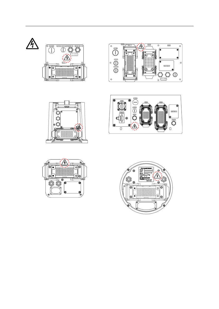
Connector plates on arm base section 


R series: 03N/05N/05L 

R series: 10N/06L 


R series : 07N/07L 

BA 


MC (Backside connector 
spec.) 

MC/MS (Base connector spec.) 


F Series Controller 

1 Safety 

Kawasaki Robot  Installation and Connection Manual 

13 

1.7  Battery and Fuse Use and Disposal 

Batteries are used for data backup in the robot arm and controller. 
If not used and disposed of properly, these batteries may malfunction, ignite, overheat, 
explode, corrode, leak, etc. Strictly observe the following precautions. 


WARNING 

1.  Only use batteries specified by Kawasaki. 
2.  Never re-charge, dismantle, convert and/or overheat batteries. 
3.  Never dispose of batteries into water or fire. 
4.  Batteries with damaged cases may short internally and must not be used. 
5.  Never short the positive and negative poles of a battery with material 

such as wire. 

Never dispose of depleted batteries with garbage that is disposed of in an 
incinerator, land-fill, dumping-ground, etc. When disposing of batteries, 
insulate with tape so as not to contact other metal. Comply with local 
regulations and rules for battery disposal. 

CAUTION 


F Series Controller 

1 Safety 

Kawasaki Robot  Installation and Connection Manual 

14 


Locations of batteries 

Battery locations of 2AA board and 1HG board are as follows: 
 

• 

2AA board 

Location Number:  E1 
Model: 

BR2032 

Manufacturer:    Panasonic 


• 

1HG board (in robot base) 

Location Number:  BAT1 
Model: 

50750-1007 or   


50750-1018 

Manufacturer: 

KHI 

Connector: 

CN3 


–  Replacement method 

Batteries can be replaced only by removing a small plate on which “BATTERY” is 
written. 


Small plate for 

battery 

F Series Controller 

1 Safety 

Kawasaki Robot  Installation and Connection Manual 

15 

1.8  Safety Features 

To safeguard the user, Kawasaki robot systems are equipped with the following features: 
 
1.  All E-stops are hard-wired. 
2.  All robot controllers are equipped with a redundant dual channel safety circuit. 

Both channels of the safety circuit must be closed to allow for robot operation in the teach 
and repeat modes. Refer to the “External I/O Manual” for details. 

3.  Safety circuits of controllers satisfy requirements of PLe in category 4 defined by ISO 

13849-1: Category and Performance level (PL) are determined by the whole system and 
conditions. 

4.  (For the arms which are equipped with servo lamp ON) When servo motor power is 

supplied, the servo ON lamp is illuminated. 

5.  The teach pendant and operation panel are equipped with E-stop switches. 

And all robot controllers have external E-stop inputs. 

6.  The TP is equipped with three-position, enabling devices. The enabling devices must be 

pressed and held down to enable motor power in teach and check modes. 

7.  TCP speeds in teach and check modes are limited to a maximum of 250 mm/s (10.0 in/s). 
8.  The speed limit can be 250 mm/s (10.0 in/s) or more in the Fast Check Mode if an 

optional Fast Check Mode switch is used (defined by ISO 10218-1). 


F Series Controller 

1 Safety 

Kawasaki Robot  Installation and Connection Manual 

16 

1.9  Emergency Movement without Drive Power 

The brake release switches (option) allow the operator to move arm without using motor drive 
power for maintenance and emergency situations. 
 

• 

Brake release switch box (option) 


Precautions 

When no motor drive power is applied to the arm, electromagnetic brakes lock to maintain the 
robot posture. Unsupported axes may fall when pressing the brake release switch. 
Axes which are overhung, particularly JT2 and JT3, will fall down the fastest, depending on 
conditions. Therefore, be careful when operating this switch. 


Operating procedure 

To manually release axes brakes, follow the procedure below. 
 
1.  Press EMERGENCY STOP of the controller and the TP, and cut off the motor power. 
2.  Make sure that the safety measures are followed. 

• 

There are no personnel around the robot. 

• 

Plug of safety fence is inserted. 


WARNING 


Position yourself to observe the entire robot arm and keep your eyes on 
the arm when operating the brake release switch. 


XRLS 

Relay connector 

F Series Controller 

1 Safety 

Kawasaki Robot  Installation and Connection Manual 

17 

3.  Provide suitable support of the robot arm, end-or-arm tooling, and payload if there is a 

risk of personal injury and facilities before using the brake release switch. 
Robot arm can be supported by using a crane and a wire (see figure below). 


4.  Connect the harness from the brake release switch box to the brake release switch 

connection connector. 

• 

Brake release switch connection connector position of F60 controller 


WARNING 


Failure to take measures may lead to an accident or damage on robot. 

CAUTION 

Do not block the front of the XRLS connector so that the connector can be 
connected to the brake release switch immediately in emergency. 

Brake release switch connection connector (XRLS) 


F Series Controller 

1 Safety 

Kawasaki Robot  Installation and Connection Manual 

18 


When connecting the brake release switch box to the sealed chassis, connect the 
wires so that the relay connector is located outside of the chassis as shown in the 
figure below. 


5.  Make sure that the brake is not released by pressing one switch. 

If the brake is released, do not use the switch. 


(1)  Press the brake release switch for the axis to release the brake for a moment. 


(2)  Press and hold the Enable switch. 


6.  Press the brake release switch for the axis to release the brake while pressing the Enable 

switch. 

CAUTION 

Stop using the brake release switch immediately if the electromagnetic brake 
is released by pressing only one switch. The switch may be defective. 

Brake release switch 

Enable switch 


Relay connector 

F Series Controller 

1 Safety 

Kawasaki Robot  Installation and Connection Manual 

19 


7.  The brake remains released until releasing the brake release switch. 

Robot axis to release the brake 


6-axis robot 


CAUTION 


For the safety, release the brake per axis. Pressing more than one switch 
at the same time may lead to an accident or damage on robot. 


F Series Controller 

2 Workflow - Robot Controller Installation and Connection 

Kawasaki Robot  Installation and Connection Manual 

20 

2  Workflow - Robot Controller Installation and Connection 

This workflow describes the robot controller. 
For the robot arms, refer to the separate manuals for them. 


Examine installation place 

(including ground) environment 

Confirm power supply voltage 

and power capacity 

Transport robot controller 

Arrange and install 

robot controller 

Connect TP and separate 

harness 

Connect peripheral control 

devices and equipment 

Connect external power


Turn ON “controller power” and 

confirm 

Turn ON “motor power” and 

confirm 

Confirm operation of robot arm 

and tool (Teach mode) 

Confirm other 

various functions 

Work completed 

Pre
p. 

w

ork


A

ctu

al

 w

ork


W

ork

 a

fte

r c

on

nec
ting


robot
 cont
rol

ler

 wi

th

 th

e r

obo

Refer to “6 Connection Instructions” and 

“Installation and Connection Manual” for 

arm. 

Refer to “External I/O Manual” for external 

control power supply. 

Refer to “3 Appearance and Specifications 

of Robot Controller”

See “4 Transportation of Robot Controller”

Refer to “5 Arrangement of Robot Controller”

Refer to “7 Connection of External Power”

Refer to “8 Connection of Peripheral 

Control Equipment”

Refer to “External I/O Manual” for external 

control power supply. 

Refer to “Operation Manual”. 

Refer to “Operation Manual”. 

Refer to “3 Appearance and Specifications 

of Robot Controller”

This manual only describes procedures from installation place examination 
to connection with external power. 

[

NOTE

F Series Controller 

3 Appearance and Specifications of Robot Controller 

Kawasaki Robot  Installation and Connection Manual 

21 

3  Appearance and Specifications of Robot Controller 

3.1  Controller Appearance 


F60 controller 


Standard open specification 


Connecting ports in the accessory panel 


Rear connecting port 


Left 

Front 

Right 

Rear 

Controller power switch 

Operation panel 

Accessory panel 

RS-232C port 

USB port 

Ethernet port 

(Connectable cable length: max. 30 m) 

TP connector 

Brake release switch connection connector 

Connectors for separate harnesses (See “6.1”.) 

External power input connector (XPOW) 

F Series Controller 

3 Appearance and Specifications of Robot Controller 

Kawasaki Robot  Installation and Connection Manual 

22 


Sealed specification 


Left 


Front 


Right 


Rear 


500 

300 

185


F Series Controller 

3 Appearance and Specifications of Robot Controller 

Kawasaki Robot  Installation and Connection Manual 

23 

3.2  TP Appearance 


Liquid crystal display 

Teach lock switch 

Emergency stop switch 

F Series Controller 

3 Appearance and Specifications of Robot Controller 

Kawasaki Robot  Installation and Connection Manual 

24 

3.3  F60 Controller Specifications 


Controller 

Specification 

Standard open 
specification 

Sealed specification 

Construction 

Open structure, direct 
cooling system 

Sealed structure, indirect 
cooling system 

Mass 

F60: 8.3 kg

*


F60: 15 kg

*


Ambient 

environment 

Temperature 

0 to 45

°

Humidity 

35 to 85 %RH (Non condensing) 

Altitude 

Up to 1000 meters above mean sea level 

Pollution 

degree 

2 or below 

3 or below 

Vibration 

condition 

10 to 57 Hz 

Half amplitude 0.075 mm 

57 to150 Hz 

1 G 

Power source 

AC 200-230 V±10%, 50/60 Hz, Single phase 

Power capacity 

Refer to the table below. 

Grounding 

Dedicated grounding (100 

 or less) 

TP cable length 

5 m/10 m/15 m 

*


Not including optional components 


Power capacity for external power connection and cable specifications 

F60 controller is equipped with a power cable with connector (AWG14, standard 2 m) as 
shown in the figure below. See “7 Connection of External Power” for the connecting method. 


Controller 

model 

Arm model 

Power 

capacity 

Recommended power 

cable size (including 

ground wire) 

Length 

requirement 

F60 controller 


R series 03 to10

*


BA/MC/MS 

*


Excluding 
10L 

2.0 kVA max. 

2.0 mm

2

 or more 

(AWG14 or more) 

200 m or less 


XPOW connector 

Model 

Manufacturer 

Cable side (female) 

1971239-1 

TYCO ELECTRONICS 

Controller side (male) 

1-1318983-2 

TYCO ELECTRONICS 


F Series Controller 

3 Appearance and Specifications of Robot Controller 

Kawasaki Robot  Installation and Connection Manual 

25 


Circuit breaker spec. for external power connection 

Controller model 

Rated current  Rated voltage 

Rated interrupting 

capacity 

F60 controller 

15 A 

AC240 V 

5000 A (UL489) 


CAUTION 


If a cable with an unspecified diameter is used for the sealed specification, 
sealability cannot be ensured, causing failure. Be sure to use cables with the 
specified diameter.


Cable: 

AWG14 (3 cables) 

Cable diameter: 

11.4

±

0.4 mm 

Green/yellow 

White 

Black 

F Series Controller 

4 Transportation of Robot Controller 

Kawasaki Robot  Installation and Connection Manual 

26 

4  Transportation of Robot Controller 

When transporting the controller, follow the procedure below. 


1.  Remove harnesses connected to TP and other external devices. 
2.  Hold the bottom of the controller firmly. 

• 

F60 controller weight: 8.3 kg (Standard open specification)/15 kg (Sealed 
specification) 

3.  Lift up the controller. 


CAUTION 


Be careful not to put an impact on the controller during transportation. 


F Series Controller 

5 Arrangement of Robot Controller 

Kawasaki Robot  Installation and Connection Manual 

27 

5  Arrangement of Robot Controller 

5.1  Horizontal Arrangement of Controller 

Horizontal arrangement is the standard for F60 controller. In order for the controller to 
maintain the proper internal temperature, the installation site must conform to the following. 


Precautions 

• 

In case of horizontal installation, up to three controllers can be stacked. 

• 

It is necessary to remove the object on the top surface of the controller in maintenance. 


Locations 

• 

Arrange the controller on a flat, horizontal stand and adjust its height so that the heights of 
controller power switch and operation switches from the floor are between 0.6 to 1.9 m. 

• 

Provide a clearance of 200 mm or more between the controller rear side and the wall. 


Standard open specification 


Double stack   

arrangement of controllers 


Controller power 

switch 

0.6 to 1.9 m 

200 mm or more 

Airflow direction of fan 

Controller power 

switch 

0.6 to 1.9 m 

200 mm or more 

Airflow direction of fan 


Content      ..      1      2      3      ..