KAWASAKI ROBOTS. ORIGINAL INSTRUCTION (v1.05) - page 4
 

  Index      Manuals     KAWASAKI ROBOTS. ORIGINAL INSTRUCTION (EN) v1.05


Search            copyright infringement  


Content      ..     2      3      4      5     ..


KAWASAKI ROBOTS. ORIGINAL INSTRUCTION (v1.05) - page 4


Additional Software Options 

98 

Update menu 

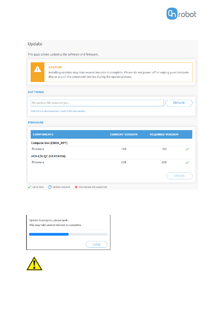
This page can be used to update the software on the Compute Box and the firmware on the devices.  


Start the software update by clicking on the 

Browse

 button to browse for the .cbu software update file.  

Then the 

Browse

  button will turn to 

Update

.  

Click on that 

Update

 button to start the software update process: 


CAUTION: 

During  the update process (takes about 5-10  minutes) DO NOT unplug 
any device or close the browser window. Otherwise the updated device 
could be damaged. 


Additional Software Options 

99 

 
If the update is finished and was successful, the following message is shown: 


Now disconnect the device and use it as usual. 


NOTE: 

If the software update failed, please contact your distributor. 


The firmware update is only required when any of the components 

  is out of date. 

To start the firmware update, click on 

UPDATE

 button in the firmware section of the page. 


CAUTION: 

During  the update process (takes about 5-10  minutes) DO NOT unplug 
any device or close the browser window. Otherwise the updated device 
could be damaged. 


If the update is finished and was successful, the following message is shown: 


Now disconnect the device and use it as usual. 


NOTE: 

If the update is failed, please contact your distributor. 


Additional Software Options 

100 

 Account settings 

This menu can be used to: 


See the currently sign-id user 


Go to 

Account settings


Sign-out 


Account settings

This page has two tabs: 


My profile

 - to see and update the currently logged in users profile (e.g.: change password)  


Users

 - to manage users (e.g.: add/remove/edit) 


On the 

My profile 

tab to change any profile data (e.g.: password) click on the 

Update profile

 button. 


Additional Software Options 

101 

On the 

Users 

tab click on the 

Add new user

 button to add more users: 


There are three user levels: 


Administrator 


Operator 


User 


Fill in the user information and click 

Save

Later on to change any user information just click on the edit 

icon. 

Additional Software Options 

102 


To prevent a user to sign-in either could be: 


deactivated by changing its 

Active

 status in the edit mode 


or removed by clicking the delete 

 icon. 


Additional Software Options 

103 

8.2


EtherNet/IP 

The OnRobot multi-device EtherNet/IP adapter can be accessed via scanner device (e.g. a robot, a PLC 
controller). Class 1 (implicit) and Class 3 (explicit) connections are available. 


NOTE: 

EtherNet/IP EDS file (v1.13 - MAJOR version 1 and MINOR version 13) is 
provided with the devices and can be located on the USB stick. 


8.2.1


Available connections and assembly instances 

Every device and device combination have 3 connections implemented:  


Exclusive Owner - RECOMMENDED to be used 


Input-only 


Listen-only 

Every connection has an [

Input / Target-to-Origin / Producing

 assembly] - [

Output / Origin-to-Target / 

Consuming 

assembly] pair. 

All assemblies are contained in 

Class 4

 and have the single 

Attribute 3

 implemented. 


NOTE: 

There is no Configuration Instance implemented, if required use instance 
number 0 and data size 0. 


The following assembly instances are available for the single devices and device combinations: 


HEX-E/H QC ....................................104 


RG2-FT ...........................................105 


RG2/6.............................................107 


VG10 / VGC10.................................109 


Gecko .............................................111 


HEX-E/H QC + RG2/6 .......................113 


HEX-E/H QC + VG10 / VGC10 ...........116 


HEX-E/H QC + Gecko .......................118 


RG2/6 + VG10 / VGC10....................120 


RG2/6 + Gecko................................124 


VG10 / VGC10 + Gecko ....................128 


Additional Software Options 

104 

HEX-E/H QC 

T->O assembly id: 100 

T->O data size: 24  bytes 

T->O parameters: 

Parameter name 

Bytes  Type 

Comments 

Start bit 


HEX Device connected 

UINT 16 

0: Disconnected 
64: HEX is connected 


HEX Status 

UINT 32  0: No error 

17 


HEX Filter 

UINT 16  See below 

49 


HEX Fx 

INT 16 

1/10 N 

65 


HEX Fy 

INT 16 

1/10 N 

81 


HEX Fz 

INT 16 

1/10 N 

97 


HEX Tx 

INT 16 

1/100  Nm 

113 


HEX Ty 

INT 16 

1/100  Nm 

129 


HEX Tz 

INT 16 

1/100  Nm 

145 


Reserved 


161 


O->T assembly id: 101 

O->T data size: 16  bytes 

O->T parameters: 

Parameter name 

Bytes  Type 

Comments 

Start bit 


HEX Zero 

UINT 16 

0: Ignored 
1: Zero 
2: Unzero 


HEX Filter 

UINT 16 

0: Ignored 
1: No filtering 
2: 500 Hz 
3: 150 Hz 
4: 50 Hz 
5: 15 Hz 
6: 5 Hz 
7: 1.5 Hz 

17 


Reserved 

12 


33 


Additional Software Options 

105 

RG2-FT 

T->O assembly id: 102 

T->O data size: 64  bytes 

T->O parameters: 

Parameter name 

Bytes  Type 

Comments 

Start bit 


RG2-FT Device connected  2 

UINT 16 

0: Disconnected 
34: RG2-FT is Connected 

Left  HEX Status 

UINT 32  0: No error 

17 

Left  HEX Filter 

UINT 16  See below 

49 

Left  HEX Fx 

INT 16 

1/10 N 

65 

Left  HEX Fy 

INT 16 

1/10 N 

81 

Left  HEX Fz 

INT 16 

1/10 N 

97 

Left  HEX Tx 

INT 16 

1/100  Nm 

113 

Left  HEX Ty 

INT 16 

1/100  Nm 

129 

Left  HEX Tz 

INT 16 

1/100  Nm 

145 


Reserved 


161 

Right  HEX Status 

UINT 32  0: No error 

193 

Right  HEX Filter 

UINT 16  See below 

225 

Right  HEX Fx 

INT 16 

1/10 N 

241 

Right  HEX Fy 

INT 16 

1/10 N 

257 

Right  HEX Fz 

INT 16 

1/10 N 

273 

Right  HEX Tx 

INT 16 

1/100  Nm 

289 

Right  HEX Ty 

INT 16 

1/100  Nm 

305 

Right  HEX Tz 

INT 16 

1/100  Nm 

321 


Reserved 


337 

Left  Proximity Distance 

INT 16 

mm 

369 

Left  Proximity Raw Dist. 

INT 16 

mm 

385 

Right  Proximity Distance 

INT 16 

mm 

401 

Right  Proximity Raw Dist. 

INT 16 

mm 

417 


RG Actual width 

INT 16 

1/10 mm 

433 


RG Status 

UINT 16 

0b___1: Busy 
0b__1_: Grip detected 
0b_1__: Left Proximity has error 
0b1___: Right Proximity has error 

449 


Reserved 


465 


Additional Software Options 

106 

O->T assembly id: 103 

O->T data size: 32  bytes 

O->T parameters: 

Parameter name 

Bytes  Type 

Comments 

Start bit 


RG Target Width 

UINT 16  1/10 mm 


RG Target Force 

UINT 16  1/10 N 

17 


RG Control 

UINT 16 

0: Ignored 
1: Move 
2: Stop 

33 


HEX Zero 

UINT 16 

0: Ignored 
1: Zero 
2: Unzero 

49 


HEX Filter 

UINT 16 

0: Ignored 
1: No filtering 
2: 500 Hz 
3: 150 Hz 
4: 50 Hz 
5: 15 Hz 
6: 5 Hz 
7: 1.5 Hz 

65 

Left  Proximity Custom Offset 

UINT 16  mm 

81 

Right  Proximity Custom Offset 

UINT 16  mm 

97 


Proximity Store Offset 

UINT 16 

0: Ignored 
1: Store actual measured value 
2: Store custom offset value 

113 


Reserved 

16 


129 


Additional Software Options 

107 

RG2/6 


NOTE: 

This  assembly instance  can  be  used for  both  single  and  dual  gripper 
configuration. Not only dual RG2 or dual RG6 but mixed configuration is 
also  possible  (RG2+RG6  or  RG6+RG2).   When  used  in  single  gripper 
configuration always use the 

Primary (Prim.)

 values. 


T->O assembly id: 104 

T->O data size: 32  bytes 

T->O parameters: 

Parameter name 

Bytes  Type 

Comments 

Start bit 

Prim.  RG Device connected 

UINT 16 

0: Disconnected 
32: RG2 is connected 
33: RG6 is connected 

Prim.  RG Actual Depth 

INT 16 

1/10 mm 

17 

Prim.  RG Actual Relative Depth  2 

INT 16 

1/10 mm 

33 

Prim.  RG Actual Width 

INT 16 

1/10 mm (with fingertip offset) 

49 

Prim.  RG Status 

UINT 16 

0b______1: 1 when in motion, 0 when not. 
The gripper will only accept new 
commands when 0. 
0b_____1_: Internal- or external grip is 
detected. 
0b____1__: Safety switch 1 is pushed. 
0b___1___: Safety circuit 1 is activated. 
The gripper will not move while this flag is 
high; can only be reset by power cycling 
the gripper. 
0b__1____: Safety switch 2 is pushed. 
0b_1_____: Safety circuit 2 is activated. 
The gripper will not move while this flag is 
high; can only be reset by power cycling 
the gripper. 
0b1______: General safety error. Possible 
cause: the gripper is booted with some 
safety switch pressed or hardware error. 

65 


Reserved 


81 

Sec.  RG Device connected 

UINT 16 

0: Disconnected 
32: RG2 is connected 
33: RG6 is connected 

129 

Sec.  RG Actual Depth 

INT 16 

1/10 mm 

145 

Sec.  RG Actual Relative Depth  2 

INT 16 

1/10 mm 

161 

Sec.  RG Actual Width 

INT 16 

1/10 mm (with fingertip offset) 

177 

Sec.  RG Status 

UINT 16  Same as above 

193 


Reserved 


209 


Additional Software Options 

108 

O->T assembly id: 105 

O->T data size: 32  bytes 

O->T parameters: 

Parameter name 

Bytes  Type 

Comments 

Start bit 

Prim.  RG Target Width 

UINT 16  1/10 mm (corrected with fingertip offset )  1 

Prim.  RG Target Force 

UINT 16  1/10 N 

17 

Prim.  RG Control 

UINT 16 

0: Ignored 
1: Start motion to target 
2: Stop the current motion 

33 

Prim.  RG Custom Fingertip offset  2 

INT 16 

Offset measured from metal (1/10mm) 

49 

Prim.  RG Store Fingertip offset 

UINT 16 

0: Ignored 
1: Store offset 

65 

Prim.  RG Reset Tool Power 

UINT 16 

0: Ignored 
1: Reset 

81 


Reserved 


97 

Sec.  RG Target Width 

UINT 16  1/10 mm (corrected with fingertip offset )  129 

Sec.  RG Target Force 

UINT 16  1/10 N 

145 

Sec.  RG Control 

UINT 16 

0: Ignored 
1: Start motion to target 
2: Stop the current motion 

161 

Sec.  RG Custom Fingertip offset  2 

INT 16 

Offset measured from metal (1/10mm) 

177 

Sec.  RG Store Fingertip offset 

UINT 16 

0: Ignored 
1: Store offset 

193 

Sec.  RG Reset Tool Power 

UINT 16 

0: Ignored 
1: Reset 

209 


Reserved 


225 


Additional Software Options 

109 

VG10 / VGC10 


NOTE: 

This  assembly instance  can  be  used for  both  single  and  dual  gripper 
configuration. When used in single gripper configuration always use the 

Primary (Prim.)

 values. 


T->O assembly id: 106 

T->O data size: 32  bytes 

T->O parameters: 

Parameter name 

Bytes  Type 

Comments 

Start bit 

Prim.  VG Device connected 

UINT 16 

0: Disconnected 
16: VG10 is connected 
17: VGC10 is connected 

Prim.  VG Current limit 

UINT 16  mA 

17 

Prim.  VG CH A actual vacuum 

UINT 16  1/10 % 

33 

Prim.  VG CH B actual vacuum 

UINT 16  1/10 % 

49 


Reserved 


65 

Sec.  VG Device connected 

UINT 16 

0: Disconnected 
16: VG10 is connected 
17: VGC10 is connected 

129 

Sec.  VG Current limit 

UINT 16  mA 

145 

Sec.  VG CH A actual vacuum 

UINT 16  1/10 % 

161 

Sec.  VG CH B actual vacuum 

UINT 16  1/10 % 

177 


Reserved 


193 


O->T assembly id: 107 

O->T data size: 32  bytes 

O->T parameters: 

Additional Software Options 

110 

Parameter name 

Bytes  Type 

Comments 

Start bit 

Prim.  VG CH A Control 

UINT 16 

0: Ignore 
1: Grip 
2: Idle 
3: Release 

Prim.  VG CH B Control 

UINT 16  Same as Channel A 

17 

Prim.  VG CH A Target Vacuum 

UINT 16  % 

33 

Prim.  VG CH B Target Vacuum 

UINT 16  % 

49 

Prim.  VG Current limit 

UINT 16  mA 

65 


Reserved 


81 

Sec.  VG CH A Control 

UINT 16 

0: Ignore 
1: Grip 
2: Idle 
3: Release 

129 

Sec.  VG CH B Control 

UINT 16  Same as Channel A 

145 

Sec.  VG CH A Target Vacuum 

UINT 16  % 

161 

Sec.  VG CH B Target Vacuum 

UINT 16  % 

177 

Sec.  VG Current limit 

UINT 16  mA 

193 


Reserved 


209 


Additional Software Options 

111 

Gecko 


NOTE: 

This  assembly instance  can  be  used for  both  single  and  dual  gripper 
configuration. When used in single gripper configuration always use the 

Primary (Prim.)

 values. 


T->O assembly id: 108 

T->O data size: 32  bytes 

T->O parameters:  

Parameter name 

Bytes  Type 

Comments 

Start bit 

Prim.  Gecko Device connected 

UINT 16 

0: Disconnected 
48: Gecko is connected 

Prim.  Gecko Status 

UINT 16 

0b___1: Part detected 
0b__1_: Pads worn 
0b_1__: Pads OUT 
0b1___: Busy 

17 

Prim.  Gecko Last Error Code 

UINT 16  0: No error 

33 

Prim. 

Actual Gecko Preload 
Force 

INT 16 

1/100  N 

49 

Prim. 

Actual Gecko Ultrasonic 
Sensor Value 

INT 16 

1/100  mm 

65 


Reserved 


81 

Sec.  Gecko Device connected 

UINT 16 

0: Disconnected 
48: Gecko is connected 

129 

Sec.  Gecko Status 

UINT 16  Same as above 

145 

Sec.  Gecko Last Error Code 

UINT 16  0: No error 

161 

Sec. 

Actual Gecko Preload 
Force 

INT 16 

1/100  N 

177 

Sec. 

Actual Gecko Ultrasonic 
Sensor Value 

INT 16 

1/100  mm 

193 


Reserved 


209 


O->T assembly id: 109 

O->T data size: 32  bytes 

O->T parameters: 

Additional Software Options 

112 

Parameter name 

Bytes  Type 

Comments 

Start bit 

Prim.  Gecko Pad Control 

UINT 16 

0: Ignored 
1: Push Pads OUT 
2: Pull Pads IN 

Prim. 

Gecko Preload Force 
Threshold 

UINT 16 

0: Ignored 
1: 50N 
2: 90N 
3: 120N 

17 

Prim.  Gecko Reset Error Logs 

UINT 16 

0: Do not reset, keep logging 
1: Reset and disable logging 

33 


Reserved 

10 


49 

Sec.  Gecko Pad Control 

UINT 16 

0: Ignored 
1: Push Pads OUT 
2: Pull Pads IN 

129 

Sec. 

Gecko Preload Force 
Threshold 

UINT 16 

0: Ignored 
1: 50N 
2: 90N 
3: 120N 

145 

Sec.  Gecko Reset Error Logs 

UINT 16 

0: Do not reset, keep logging 
1: Reset and disable logging 

161 


Reserved 

10 


177 


Additional Software Options 

113 

HEX-E/H QC + 

RG2/6 

T->O assembly id: 150 

T->O data size: 40  bytes 

T->O parameters: 

Additional Software Options 

114 

Parameter name 

Bytes  Type 

Comments 

Start bit 


HEX Device connected 

UINT 16 

0: Disconnected 
64: HEX is connected 


HEX Status 

UINT 32  0: No error 

17 


HEX Filter 

UINT 16  See below 

49 


HEX Fx 

INT 16 

1/10 N 

65 


HEX Fy 

INT 16 

1/10 N 

81 


HEX Fz 

INT 16 

1/10 N 

97 


HEX Tx 

INT 16 

1/100  Nm 

113 


HEX Ty 

INT 16 

1/100  Nm 

129 


HEX Tz 

INT 16 

1/100  Nm 

145 


Reserved 


161 

Prim.  RG Device connected 

UINT 16 

0: Disconnected 
32: RG2 is connected 
33: RG6 is connected 

193 

Prim.  RG Actual Depth 

INT 16 

1/10 mm 

209 

Prim.  RG Actual Relative Depth  2 

INT 16 

1/10 mm 

225 

Prim.  RG Actual Width 

INT 16 

1/10 mm (with fingertip offset) 

241 

Prim.  RG Status 

UINT 16 

0b______1: 1 when in motion, 0 
when not. The gripper will only 
accept new commands when 0. 
0b_____1_: Internal- or external 
grip is detected. 
0b____1__: Safety switch 1 is 
pushed. 
0b___1___: Safety circuit 1 is 
activated. The gripper will not 
move while this flag is high; can 
only be reset by power cycling the 
gripper. 
0b__1____: Safety switch 2 is 
pushed. 
0b_1_____: Safety circuit 2 is 
activated. The gripper will not 
move while this flag is high; can 
only be reset by power cycling the 
gripper. 
0b1______: General safety error. 
Possible cause: the gripper is 
booted with some safety switch 
pressed or hardware error. 

257 


Reserved 


273 


Additional Software Options 

115 

O->T assembly id: 151 

O->T data size: 32  bytes 

O->T parameters: 

Parameter name 

Bytes  Type 

Comments 

Start 
bit 


HEX Zero 

UINT 16 

0: Ignored 
1: Zero 
2: Unzero 


HEX Filter 

UINT 16 

0: Ignored 
1: No filtering 
2: 500 Hz 
3: 150 Hz 
4: 50 Hz 
5: 15 Hz 
6: 5 Hz 
7: 1.5 Hz 

17 


Reserved 

12 


33 

Prim.  RG Target Width 

UINT 16 

1/10 mm (corrected with fingertip offset 

129 

Prim.  RG Target Force 

UINT 16  1/10 N 

145 

Prim.  RG Control 

UINT 16 

0: Ignored 
1: Start motion to target 
2: Stop the current motion 

161 

Prim.  RG Custom Fingertip offset  2 

INT 16 

Offset measured from metal (1/10mm)  177 

Prim.  RG Store Fingertip offset 

UINT 16 

0: Ignored 
1: Store offset 

193 

Prim.  RG Reset Tool Power 

UINT 16 

0: Ignored 
1: Reset 

209 


Reserved 


225 


Additional Software Options 

116 

HEX-E/H QC + VG10 

/ VGC10 

T->O assembly id: 152 

T->O data size: 40  bytes 

T->O parameters: 

Parameter name 

Bytes  Type 

Comments 

Start bit 


HEX Device connected 

UINT 16 

0: Disconnected 
64: HEX is connected 


HEX Status 

UINT 32  0: No error 

17 


HEX Filter 

UINT 16  See below 

49 


HEX Fx 

INT 16 

1/10 N 

65 


HEX Fy 

INT 16 

1/10 N 

81 


HEX Fz 

INT 16 

1/10 N 

97 


HEX Tx 

INT 16 

1/100  Nm 

113 


HEX Ty 

INT 16 

1/100  Nm 

129 


HEX Tz 

INT 16 

1/100  Nm 

145 


Reserved 


161 

Prim.  VG Device connected 

UINT 16 

0: Disconnected 
16: VG10 is connected 
17: VGC10 is connected 

193 

Prim.  VG Current limit 

UINT 16  mA 

209 

Prim.  VG CH A actual vacuum 

UINT 16  1/10 % 

225 

Prim.  VG CH B actual vacuum 

UINT 16  1/10 % 

241 


Reserved 


257 


O->T assembly id: 153 

O->T data size: 32  bytes 

O->T parameters: 

Additional Software Options 

117 

Parameter name 

Bytes  Type 

Comments 

Start bit 


HEX Zero 

UINT 16 

0: Ignored 
1: Zero 
2: Unzero 


HEX Filter 

UINT 16 

0: Ignored 
1: No filtering 
2: 500 Hz 
3: 150 Hz 
4: 50 Hz 
5: 15 Hz 
6: 5 Hz 
7: 1.5 Hz 

17 


Reserved 

12 


33 

Prim.  VG CH A Control 

UINT 16 

0: Ignore 
1: Grip 
2: Idle 
3: Release 

129 

Prim.  VG CH B Control 

UINT 16  Same as Channel A 

145 

Prim.  VG CH A Target Vacuum 

UINT 16  % 

161 

Prim.  VG CH B Target Vacuum 

UINT 16  % 

177 

Prim.  VG Current limit 

UINT 16  mA 

193 

Reserved 


209 


Additional Software Options 

118 

HEX-E/H QC + Gecko 

T->O assembly id: 154 

T->O data size: 40  bytes 

T->O parameters:  

Parameter name 

Bytes  Type 

Comments 

Start bit 


HEX Device connected 

UINT 16 

0: Disconnected 
64: HEX is connected 


HEX Status 

UINT 32  0: No error 

17 


HEX Filter 

UINT 16  See below 

49 


HEX Fx 

INT 16 

1/10 N 

65 


HEX Fy 

INT 16 

1/10 N 

81 


HEX Fz 

INT 16 

1/10 N 

97 


HEX Tx 

INT 16 

1/100  Nm 

113 


HEX Ty 

INT 16 

1/100  Nm 

129 


HEX Tz 

INT 16 

1/100  Nm 

145 


Reserved 


161 

Prim.  Gecko Device connected 

UINT 16 

0: Disconnected 
48: Gecko is connected 

193 

Prim.  Gecko Status 

UINT 16 

0b___1: Part detected 
0b__1_: Pads worn 
0b_1__: Pads OUT 
0b1___: Busy 

209 

Prim.  Gecko Last Error Code 

UINT 16  0: No error 

225 

Prim. 

Actual Gecko Preload 
Force 

INT 16 

1/100  N 

241 

Prim. 

Actual Gecko Ultrasonic 
Sensor Value 

INT 16 

1/100  mm 

257 


Reserved 


273 


O->T assembly id: 155 

O->T data size: 32  bytes 

O->T parameters: 

Additional Software Options 

119 

Parameter name 

Bytes  Type 

Comments 

Start bit 


HEX Zero 

UINT 16 

0: Ignored 
1: Zero 
2: Unzero 


HEX Filter 

UINT 16 

0: Ignored 
1: No filtering 
2: 500 Hz 
3: 150 Hz 
4: 50 Hz 
5: 15 Hz 
6: 5 Hz 
7: 1.5 Hz 

17 


Reserved 

12 


33 

Prim.  Gecko Pad Control 

UINT 16 

0: Ignored 
1: Push Pads OUT 
2: Pull Pads IN 

129 

Prim. 

Gecko Preload Force 
Threshold 

UINT 16 

0: Ignored 
1: 50N 
2: 90N 
3: 120N 

145 

Prim.  Gecko Reset Error Logs 

UINT 16 

0: Do not reset, keep logging 
1: Reset and disable logging 

161 


Reserved 

10 


177 


Additional Software Options 

120 

RG2/6 + VG10 / 

VGC10 

T->O assembly id: 156 

T->O data size: 64  bytes 

T->O parameters:  

Additional Software Options 

121 

Parameter name 

Bytes  Type 

Comments 

Start 
bit 

Prim.  RG Device connected 

UINT 16 

0: Disconnected 
32: RG2 is connected 
33: RG6 is connected 

Prim.  RG Actual Depth 

INT 16 

1/10 mm 

17 

Prim.  RG Actual Relative Depth  2 

INT 16 

1/10 mm 

33 

Prim.  RG Actual Width 

INT 16 

1/10 mm (with fingertip offset) 

49 

Prim.  RG Status 

UINT 16 

0b______1: 1 when in motion, 0 when 
not. The gripper will only accept new 
commands when 0. 
0b_____1_: Internal- or external grip is 
detected. 
0b____1__: Safety switch 1 is pushed. 
0b___1___: Safety circuit 1 is activated. 
The gripper will not move while this 
flag is high; can only be reset by power 
cycling the gripper. 
0b__1____: Safety switch 2 is pushed. 
0b_1_____: Safety circuit 2 is activated. 
The gripper will not move while this 
flag is high; can only be reset by power 
cycling the gripper. 
0b1______: General safety error. 
Possible cause: the gripper is booted 
with some safety switch pressed or 
hardware error. 

65 


Reserved 


81 

Sec.  RG Device connected 

UINT 16 

0: Disconnected 
32: RG2 is connected 
33: RG6 is connected 

129 

Sec.  RG Actual Depth 

INT 16 

1/10 mm 

145 

Sec.  RG Actual Relative Depth  2 

INT 16 

1/10 mm 

161 

Sec.  RG Actual Width 

INT 16 

1/10 mm (with fingertip offset) 

177 

Sec.  RG Status 

UINT 16  Same as above 

193 


Reserved 


209 

Prim.  VG Device connected 

UINT 16 

0: Disconnected 
16: VG10 is connected 
17: VGC10 is connected 

257 

Prim.  VG Current limit 

UINT 16  mA 

273 

Prim.  VG CH A actual vacuum 

UINT 16  1/10 % 

289 

Prim.  VG CH B actual vacuum 

UINT 16  1/10 % 

305 


Reserved 


321 

Sec.  VG Device connected 

UINT 16 

0: Disconnected 
16: VG10 is connected 
17: VGC10 is connected 

385 

Sec.  VG Current limit 

UINT 16  mA 

401 

Sec.  VG CH A actual vacuum 

UINT 16  1/10 % 

417 

Sec.  VG CH B actual vacuum 

UINT 16  1/10 % 

433 


Reserved 


449 

Additional Software Options 

122 


O->T assembly id: 157 

O->T data size: 64  bytes 

O->T parameters: 

Additional Software Options 

123 

Parameter name 

Bytes  Type 

Comments 

Start 
bit 

Prim.  RG Target Width 

UINT 16 

1/10 mm (corrected with fingertip offset 

Prim.  RG Target Force 

UINT 16  1/10 N 

17 

Prim.  RG Control 

UINT 16 

0: Ignored 
1: Start motion to target 
2: Stop the current motion 

33 

Prim.  RG Custom Fingertip offset  2 

INT 16 

Offset measured from metal (1/10mm)  49 

Prim.  RG Store Fingertip offset 

UINT 16 

0: Ignored 
1: Store offset 

65 

Prim.  RG Reset Tool Power 

UINT 16 

0: Ignored 
1: Reset 

81 


Reserved 


97 

Sec.  RG Target Width 

UINT 16 

1/10 mm (corrected with fingertip offset 

129 

Sec.  RG Target Force 

UINT 16  1/10 N 

145 

Sec.  RG Control 

UINT 16 

0: Ignored 
1: Start motion to target 
2: Stop the current motion 

161 

Sec.  RG Custom Fingertip offset  2 

INT 16 

Offset measured from metal (1/10mm)  177 

Sec.  RG Store Fingertip offset 

UINT 16 

0: Ignored 
1: Store offset 

193 

Sec.  RG Reset Tool Power 

UINT 16 

0: Ignored 
1: Reset 

209 


Reserved 


225 

Prim.  VG CH A Control 

UINT 16 

0: Ignore 
1: Grip 
2: Idle 
3: Release 

257 

Prim.  VG CH B Control 

UINT 16  Same as Channel A 

273 

Prim.  VG CH A Target Vacuum 

UINT 16  % 

289 

Prim.  VG CH B Target Vacuum 

UINT 16  % 

305 

Prim.  VG Current limit 

UINT 16  mA 

321 


Reserved 


337 

Sec.  VG CH A Control 

UINT 16 

0: Ignore 
1: Grip 
2: Idle 
3: Release 

385 

Sec.  VG CH B Control 

UINT 16  Same as Channel A 

401 

Sec.  VG CH A Target Vacuum 

UINT 16  % 

417 

Sec.  VG CH B Target Vacuum 

UINT 16  % 

433 

Sec.  VG Current limit 

UINT 16  mA 

449 


Reserved 


465 

Additional Software Options 

124 


RG2/6 + Gecko 


T->O assembly id: 158 

T->O data size: 64  bytes 

T->O parameters: 

Additional Software Options 

125 

Parameter name 

Bytes  Type 

Comments 

Start bit 

Prim.  RG Device connected 

UINT 16 

0: Disconnected 
32: RG2 is connected 
33: RG6 is connected 

Prim.  RG Actual Depth 

INT 16 

1/10 mm 

17 

Prim.  RG Actual Relative Depth  2 

INT 16 

1/10 mm 

33 

Prim.  RG Actual Width 

INT 16 

1/10 mm (with fingertip offset) 

49 

Prim.  RG Status 

UINT 16 

0b______1: 1 when in motion, 0 
when not. The gripper will only 
accept new commands when 0. 
0b_____1_: Internal- or external grip 
is detected. 
0b____1__: Safety switch 1 is pushed. 
0b___1___: Safety circuit 1 is 
activated. The gripper will not move 
while this flag is high; can only be 
reset by power cycling the gripper. 
0b__1____: Safety switch 2 is pushed. 
0b_1_____: Safety circuit 2 is 
activated. The gripper will not move 
while this flag is high; can only be 
reset by power cycling the gripper. 
0b1______: General safety error. 
Possible cause: the gripper is booted 
with some safety switch pressed or 
hardware error. 

65 


Reserved 


81 

Sec.  RG Device connected 

UINT 16 

0: Disconnected 
32: RG2 is connected 
33: RG6 is connected 

129 

Sec.  RG Actual Depth 

INT 16 

1/10 mm 

145 

Sec.  RG Actual Relative Depth  2 

INT 16 

1/10 mm 

161 

Sec.  RG Actual Width 

INT 16 

1/10 mm (with fingertip offset) 

177 

Sec.  RG Status 

UINT 16  Same as above 

193 


Reserved 


209 

Prim.  Gecko Device connected 

UINT 16 

0: Disconnected 
48: Gecko is connected 

257 

Prim.  Gecko Status 

UINT 16 

0b___1: Part detected 
0b__1_: Pads worn 
0b_1__: Pads OUT 
0b1___: Busy 

273 

Prim.  Gecko Last Error Code 

UINT 16  0: No error 

289 

Prim. 

Actual Gecko Preload 
Force 

INT 16 

1/100  N 

305 

Prim. 

Actual Gecko Ultrasonic 
Sensor Value 

INT 16 

1/100  mm 

321 


Reserved 


337 

Sec.  Gecko Device connected 

UINT 16 

0: Disconnected 
48: Gecko is connected 

385 

Additional Software Options 

126 

Sec.  Gecko Status 

UINT 16  Same as above 

401 

Sec.  Gecko Last Error Code 

UINT 16  0: No error 

417 

Sec. 

Actual Gecko Preload 
Force 

INT 16 

1/100  N 

433 

Sec. 

Actual Gecko Ultrasonic 
Sensor Value 

INT 16 

1/100  mm 

449 


Reserved 


465 


O->T assembly id: 159 

O->T data size: 64  bytes 

O->T parameters: 

Additional Software Options 

127 

Parameter name 

Bytes  Type 

Comments 

Start 
bit 

Prim.  RG Target Width 

UINT 16  1/10 mm (corrected with fingertip offset )  1 

Prim.  RG Target Force 

UINT 16  1/10 N 

17 

Prim.  RG Control 

UINT 16 

0: Ignored 
1: Start motion to target 
2: Stop the current motion 

33 

Prim.  RG Custom Fingertip offset  2 

INT 16 

Offset measured from metal (1/10mm) 

49 

Prim.  RG Store Fingertip offset 

UINT 16 

0: Ignored 
1: Store offset 

65 

Prim.  RG Reset Tool Power 

UINT 16 

0: Ignored 
1: Reset 

81 


Reserved 


97 

Sec.  RG Target Width 

UINT 16  1/10 mm (corrected with fingertip offset )  129 

Sec.  RG Target Force 

UINT 16  1/10 N 

145 

Sec.  RG Control 

UINT 16 

0: Ignored 
1: Start motion to target 
2: Stop the current motion 

161 

Sec.  RG Custom Fingertip offset  2 

INT 16 

Offset measured from metal (1/10mm) 

177 

Sec.  RG Store Fingertip offset 

UINT 16 

0: Ignored 
1: Store offset 

193 

Sec.  RG Reset Tool Power 

UINT 16 

0: Ignored 
1: Reset 

209 


Reserved 


225 

Prim.  Gecko Pad Control 

UINT 16 

0: Ignored 
1: Push Pads OUT 
2: Pull Pads IN 

257 

Prim. 

Gecko Preload Force 
Threshold 

UINT 16 

0: Ignored 
1: 50N 
2: 90N 
3: 120N 

273 

Prim.  Gecko Reset Error Logs 

UINT 16 

0: Do not reset, keep logging 
1: Reset and disable logging 

289 


Reserved 

10 


305 

Sec.  Gecko Pad Control 

UINT 16 

0: Ignored 
1: Push Pads OUT 
2: Pull Pads IN 

385 

Sec. 

Gecko Preload Force 
Threshold 

UINT 16 

0: Ignored 
1: 50N 
2: 90N 
3: 120N 

401 

Sec.  Gecko Reset Error Logs 

UINT 16 

0: Do not reset, keep logging 
1: Reset and disable logging 

417 


Reserved 

10 


433 


Additional Software Options 

128 

VG10 / VGC10 + 

Gecko 

T->O assembly id: 160 

T->O data size: 64  bytes 

T->O parameters: 

Parameter name 

Bytes  Type 

Comments 

Start bit 

Prim.  VG Device connected 

UINT 16 

0: Disconnected 
16: VG10 is connected 
17: VGC10 is connected 

Prim.  VG Current limit 

UINT 16  mA 

17 

Prim.  VG CH A actual vacuum 

UINT 16  1/10 % 

33 

Prim.  VG CH B actual vacuum 

UINT 16  1/10 % 

49 


Reserved 


65 

Sec.  VG Device connected 

UINT 16 

0: Disconnected 
16: VG10 is connected 
17: VGC10 is connected 

129 

Sec.  VG Current limit 

UINT 16  mA 

145 

Sec.  VG CH A actual vacuum 

UINT 16  1/10 % 

161 

Sec.  VG CH B actual vacuum 

UINT 16  1/10 % 

177 


Reserved 


193 

Prim.  Gecko Device connected 

UINT 16 

0: Disconnected 
48: Gecko is connected 

257 

Prim.  Gecko Status 

UINT 16 

0b___1: Part detected 
0b__1_: Pads worn 
0b_1__: Pads OUT 
0b1___: Busy 

273 

Prim.  Gecko Last Error Code 

UINT 16  0: No error 

289 

Prim. 

Actual Gecko Preload 
Force 

INT 16 

1/100  N 

305 

Prim. 

Actual Gecko Ultrasonic 
Sensor Value 

INT 16 

1/100  mm 

321 


Reserved 


337 

Sec.  Gecko Device connected 

UINT 16 

0: Disconnected 
48: Gecko is connected 

385 

Sec.  Gecko Status 

UINT 16  Same as above 

401 

Sec.  Gecko Last Error Code 

UINT 16  0: No error 

417 

Sec. 

Actual Gecko Preload 
Force 

INT 16 

1/100  N 

433 

Sec. 

Actual Gecko Ultrasonic 
Sensor Value 

INT 16 

1/100  mm 

449 


Reserved 


465 


Additional Software Options 

129 

O->T assembly id: 161 

O->T data size: 64  bytes 

O->T parameters:  

Parameter name 

Bytes  Type 

Comments 

Start bit 

Prim.  VG CH A Control 

UINT 16 

0: Ignore 
1: Grip 
2: Idle 
3: Release 

Prim.  VG CH B Control 

UINT 16  Same as Channel A 

17 

Prim.  VG CH A Target Vacuum 

UINT 16  % 

33 

Prim.  VG CH B Target Vacuum 

UINT 16  % 

49 

Prim.  VG Current limit 

UINT 16  mA 

65 


Reserved 


81 

Sec.  VG CH A Control 

UINT 16 

0: Ignore 
1: Grip 
2: Idle 
3: Release 

129 

Sec.  VG CH B Control 

UINT 16  Same as Channel A 

145 

Sec.  VG CH A Target Vacuum 

UINT 16  % 

161 

Sec.  VG CH B Target Vacuum 

UINT 16  % 

177 

Sec.  VG Current limit 

UINT 16  mA 

193 


Reserved 


209 

Prim.  Gecko Pad Control 

UINT 16 

0: Ignored 
1: Push Pads OUT 
2: Pull Pads IN 

257 

Prim. 

Gecko Preload Force 
Threshold 

UINT 16 

0: Ignored 
1: 50N 
2: 90N 
3: 120N 

273 

Prim.  Gecko Reset Error Logs 

UINT 16 

0: Do not reset, keep logging 
1: Reset and disable logging 

289 


Reserved 

10 


305 

Sec.  Gecko Pad Control 

UINT 16 

0: Ignored 
1: Push Pads OUT 
2: Pull Pads IN 

385 

Sec. 

Gecko Preload Force 
Threshold 

UINT 16 

0: Ignored 
1: 50N 
2: 90N 
3: 120N 

401 

Sec.  Gecko Reset Error Logs 

UINT 16 

0: Do not reset, keep logging 
1: Reset and disable logging 

417 


Reserved 

10 


433 


Content      ..     2      3      4      5     ..