CLOCK AND WATCH ESCAPEMENT MECHANICS (1997) - page 3
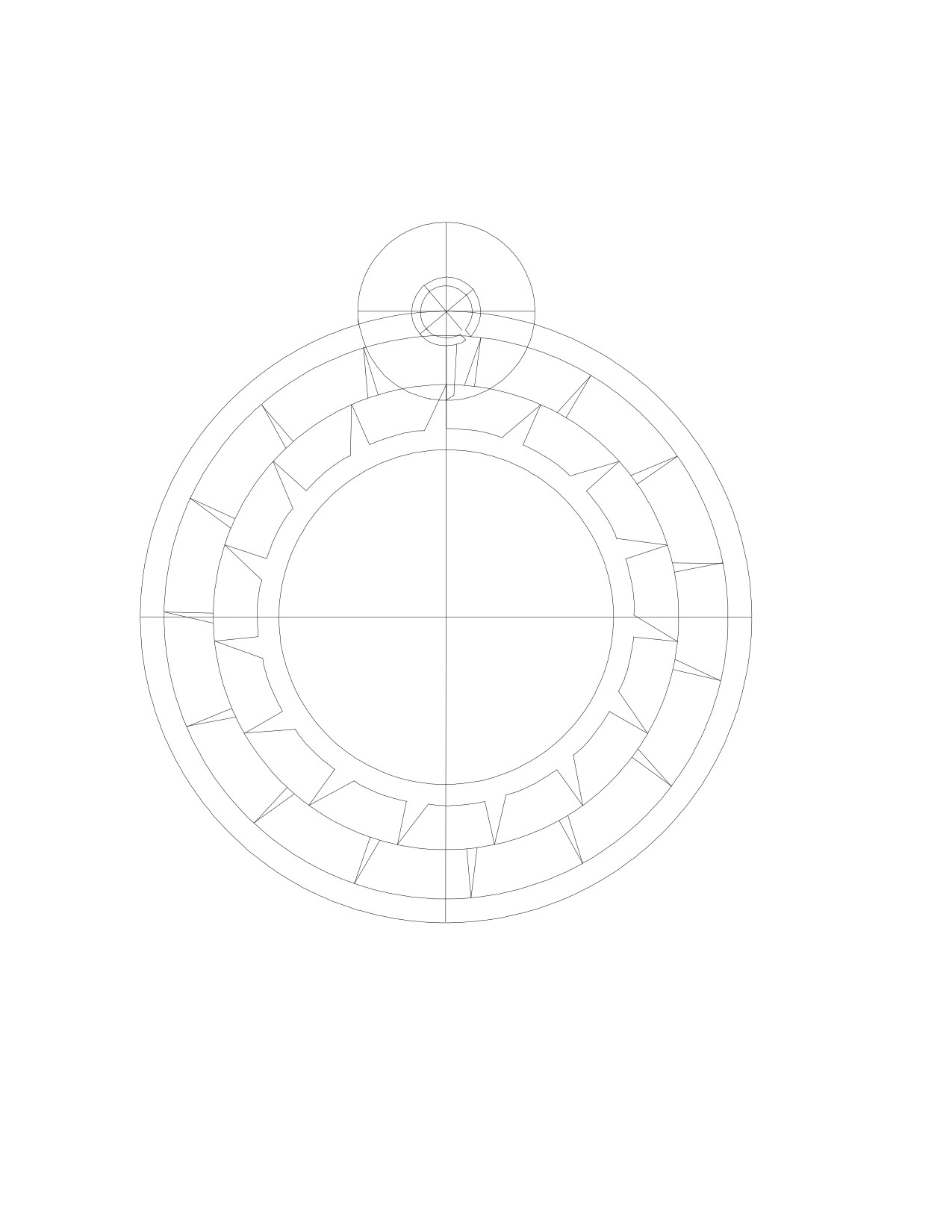
Rotate the escape wheel clockwise by 12º: in other words, 2º after the tooth has been
released by the locking jewel. Rotate the locking jewel until it is at the point where it has
just released the escape wheel's tooth. Then draw the impulse arm next to the inner escape
wheel's tooth in its path.
By analyzing the drawing, you would find that the escape wheel provides a consider-
able impulse during the locking phase, not only during the impulse phase.
In this example, I chose that the locking jewel would rotate by 90º during lock and
the escape wheel by 10º, and that the impulse arm would rotate by 60º during impulse and
the escape wheel by 22º. Try using different angles to determine what effect such changes
would have on the sizes of the locking jewel, the impulse arm, and the inner escape wheel.
66
20: The Chronometer Escapement.
The most important advantage that the Chronometer Escapement has over the Swiss
Lever is that lubrication of the escape wheel teeth is not required: the balance's impulse
pallet and the escape tooth appear to roll together rather than to slide across one another
(as in the Swiss Lever), so there is much less friction in the Chronometer escapement.
Since the lubricant may change viscosity as the temperature changes, and may even dry up
over time, it is preferable not to lubricate the escapement unless necessary: since the
Chronometer escapement has a much lower friction loss, the ability to make it run dry
would result in a more consistent timekeeper.
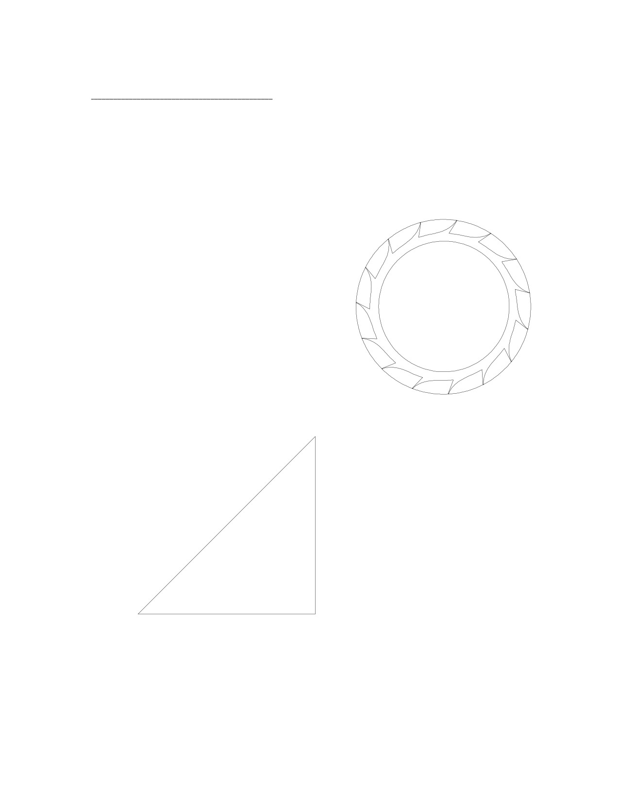
While the principles of this escapement are
straightforward, the drawing is difficult to create,
and there is plenty of math involved. Draw a 15
tooth escape wheel inside a 6 inch diameter circle.
Draw a 3.25 inch line from the center of the es-
cape wheel to the edge of the circle. Then draw a
vertical line, which will represent the detent, a
quarter of an inch away from the edge of the circle.
Rotate this line clockwise by 45º, and place it over
the center of the circle and crossing the detent line
to create a triangle:
balance circle
center
The top right corner
will become the balance's
circle center. To calculate
T
the distance (T) between
detent
the two circle centers:
line
let T = 3.25 / cos 45
circle
= 4.596"
45º
center
3.25 inches
67
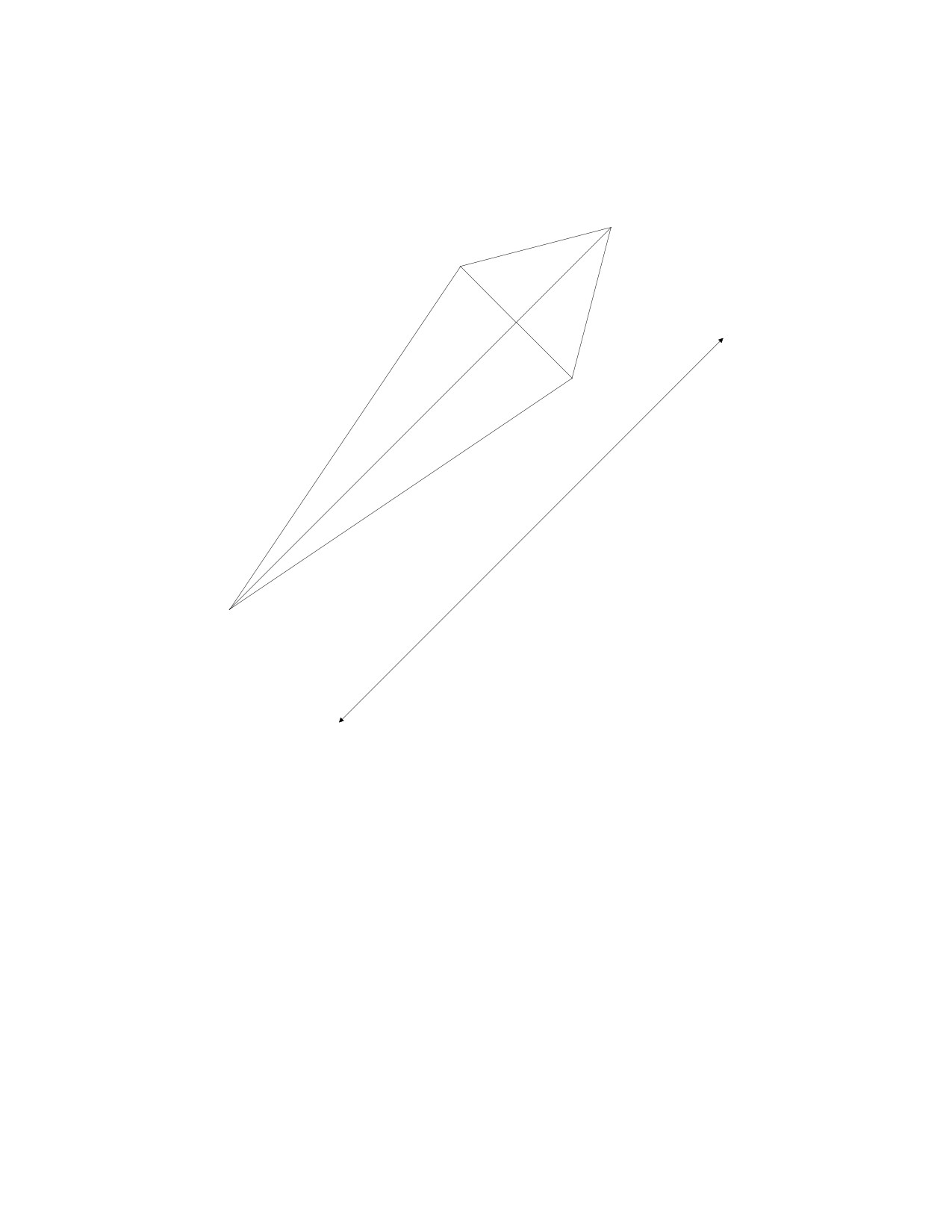
You need to find the radius of the impulse pallet's circle (X), that is, the circle that
will trace the path of the impulse pallet. If the escape wheel rotates by 22º (24º less 2º for
drop) during impulse, you could draw the following triangles:
X
C
A
escape
circle
radius = 3"
B
11º
11º
T = 4.596
= A + B
B = 3 cos 11 = 2.945
T = A + B = 4.596
A = 4.596 - 2.945 = 1.651
C = 3 sin 11 = 0.572
2
2
X2= A2+C2
=1.651
+0.572
X = 1.747
Draw a circle with a radius of 1.747 inches and place its center on the point where the
detent line and the T line meet. Another method could be used to calculate X: it is shown
on page 73.
68
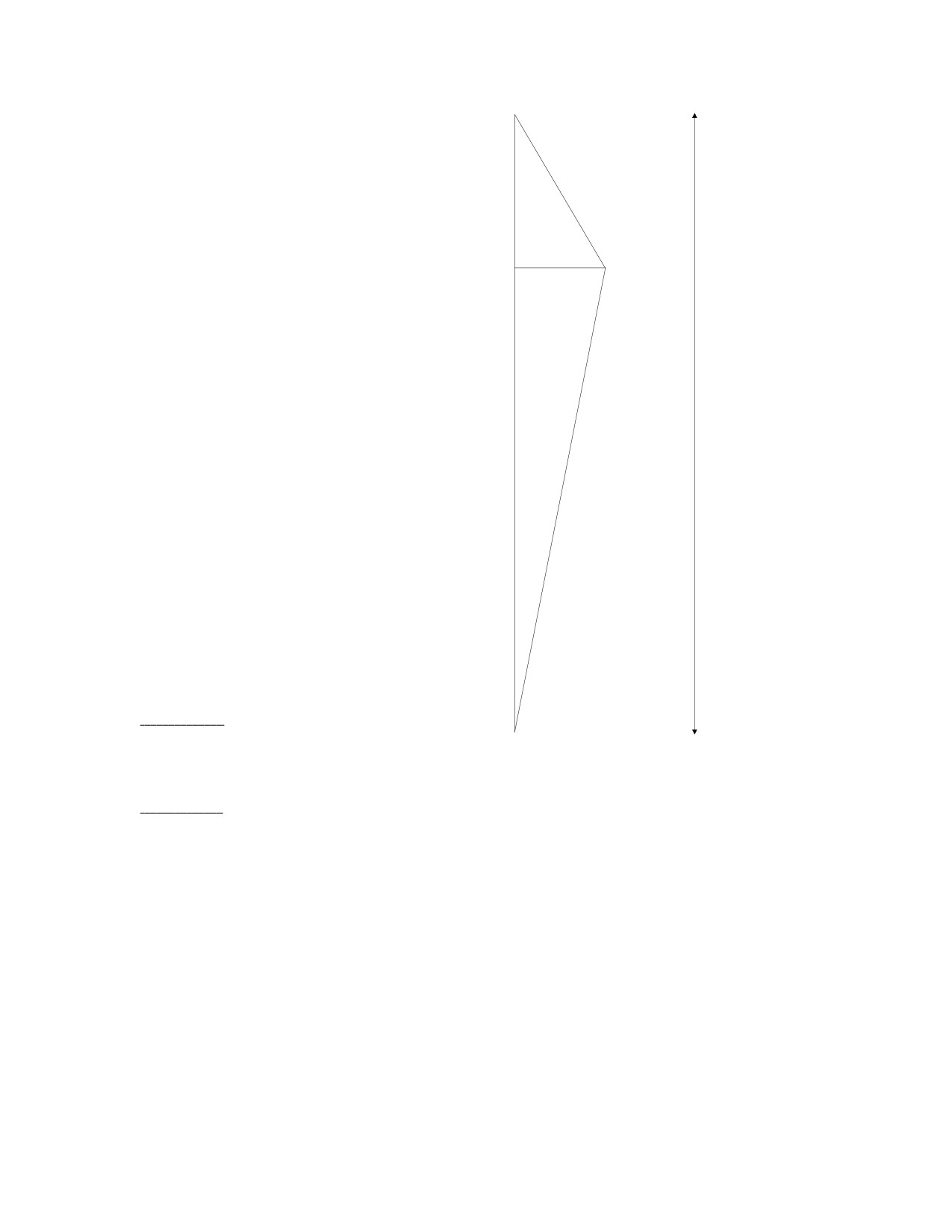
Once the impulse portion of the
escapement it finished, it is necessary to
calculate the dimensions of the discharging
30º
R
pallet's circle and the gold spring's circle for
the detent. If the discharging pallet rotates by
E
30º, and the gold spring rotates by 2º, during
discharge, we get another set of
triangles.
(These are not drawn to scale.)
R cos 30 + G cos 2 = 6.5
R sin 30 = G sin 2
F
D= E + F
...and solve the equations.
= 6.5"
0.5 R = 0.035 G
G
so R = 0.07 G
Substituting:
2º
0.866 R + 0.999 G = 6.5
(0.866 x 0.07) G + 0.999 G = 6.5
1.060 G = 6.5
G = 6.132"
R = 0.07 G = 0.07 x 6.132
R = 0.429"
Draw a circle with a radius of 0.429" and place it such that its center lies on the point
where the detent line and line T intersect. The discharge pallet's circle will then be cen-
tered inside the impulse pallet's circle. Draw the gold spring's line on the detent line and
make it 6.132 inches long from the point about which it would rotate, 6.5 inches below the
center of the impulse pallet's circle. The longer the gold spring's line, the better, because
the locking pallet would have a greater arc relative to the arc of the gold spring's line as it
rotates to discharge the escape wheel. I chose a length of 6.5 inches, or twice the displace-
ment from the horizontal line to the impulse pallet's circle center.
69
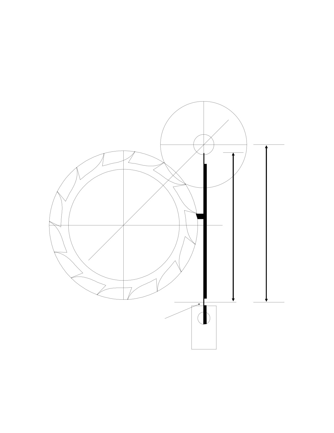
Rotate the escape wheel until the impulse pallet's circle is centered between two
escape teeth. Then draw the detent pallet on the detent arm: place it just below the tooth,
as shown, and with a small amount of lock. The thick line next to the gold spring line
represents the detent arm. The rectangle below represents the base of the detent arm. The
gold spring's circle is not included in this drawing because of its size, but it would be
needed for the simulation.
6.132"
6.5"
gold spring
circle center
70
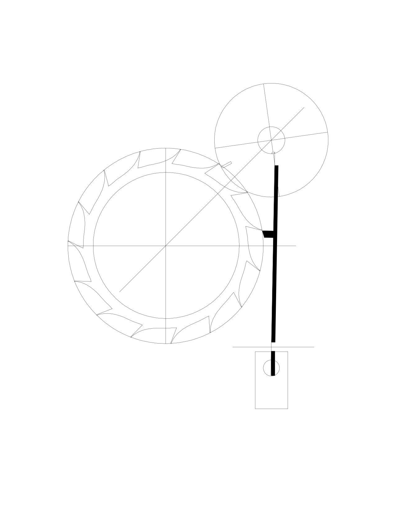
Rotate the detent arm and gold spring assembly clockwise by 1º, until the detent
pallet just releases the escape tooth. Rotate the discharge pallet counterclockwise by 8º.
Draw the impulse pallet at the edge of the impulse pallet's circle, just inside the escape
wheel's circle.
Rotate the detent clockwise by 1º extra, and the discharge and impulse pallets
counterclockwise until the discharge pallet meets the gold spring. Then rotate the escape
wheel until it meets the impulse pallet. The discharge and impulse pallets must rotate by
enough to allow the escape wheel to move forwards until the tooth clears the detent
before the detent is released. Otherwise, there will be some bent escape teeth.
71
21: Daniel's Independent Double-Escape Wheel Escapement.
This escapement brings together the best of the Chronometer and the Swiss Lever.
The Swiss Lever is essentially self-starting. The Chronometer is more efficient and its es-
cape wheel is not lubricated. The combination is the best of both worlds.
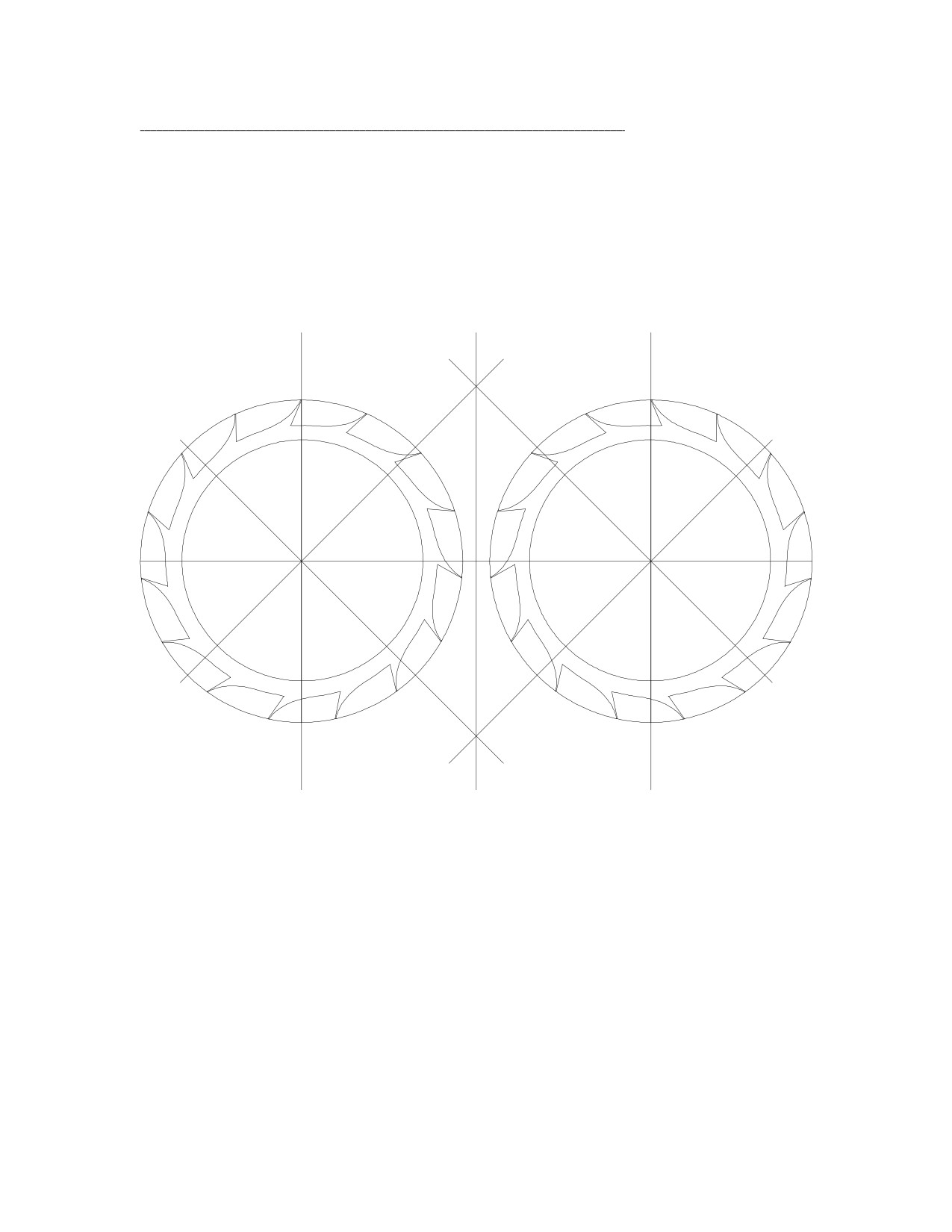
Take the Chronometer's escape wheel, duplicate it, flip it over (to create a mirror-
image of it), and place it next to the other with a gap of half an inch. Draw a horizontal
line, rotate it by 45º, and place it over the center of each escape wheel. Rotate it by 90º,
and place it over the center of each escape wheel.
45º
45º
45º
45º
72
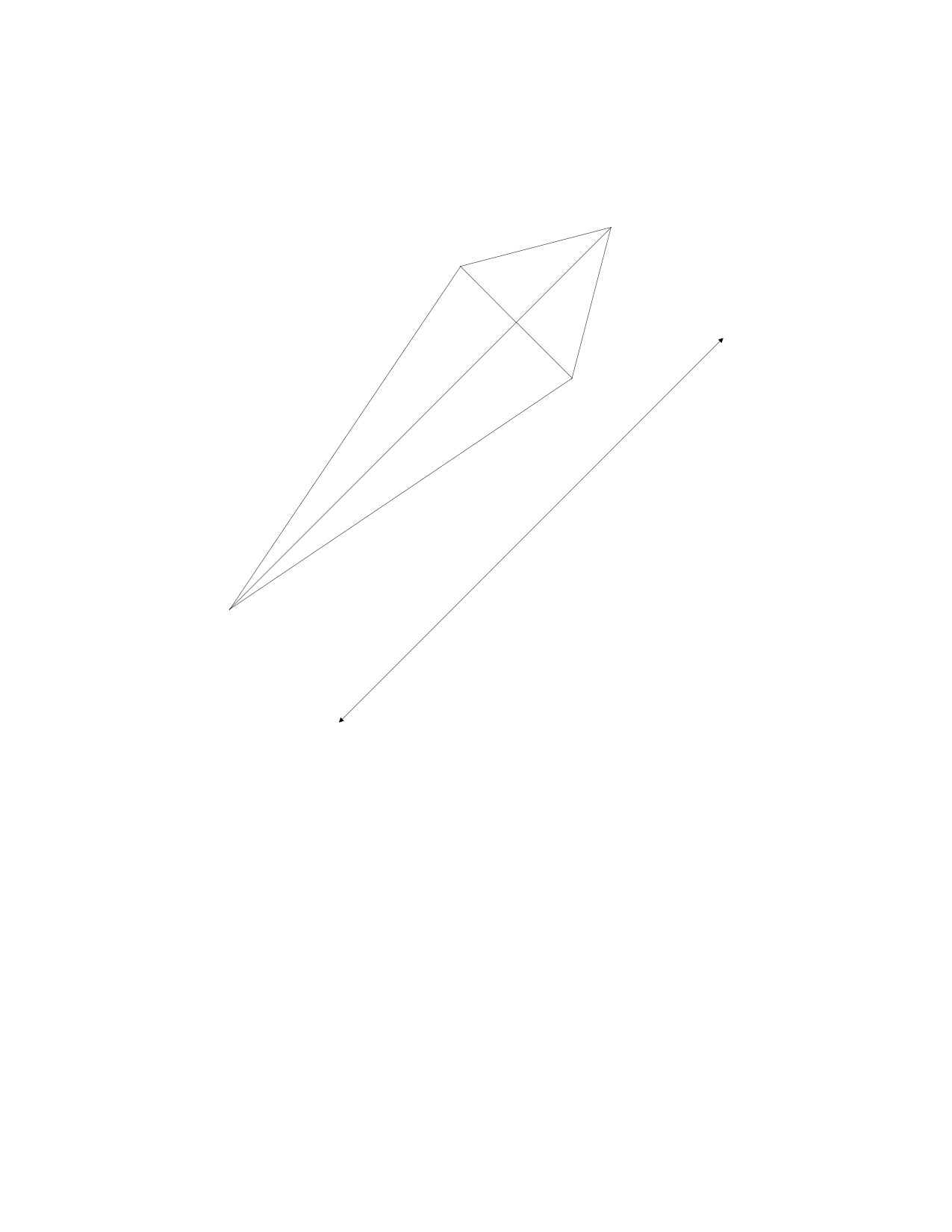
You need to find the radius of the impulse pallet's circle (X), as for the Chronometer.
If the escape wheel rotates 18º (24º less 3º twice for drop) during impulse, you could
draw the following triangles:
X
C
A
escape
circle
radius = 3"
B
9º
9º
T = 4.596
= A + B
This calculation is similar to the one on page 68. It could also be calculated using a
different method, and one formula:
2
2
X2
=3
+4.596
−(2)(
3)(
4.596)(cos
9)
X = 1.699
Draw a circle with a radius of 1.699 inches and place its center on the point where lines
(1) and (2) intersect.
73
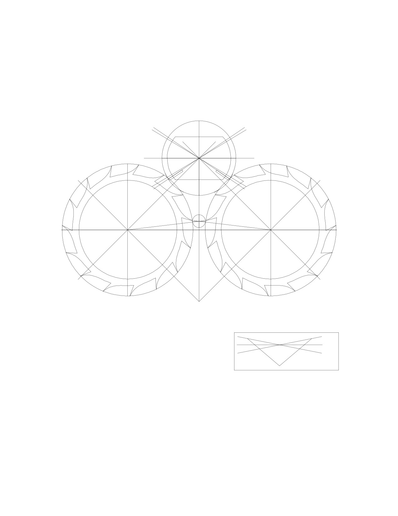
Draw a horizontal line, (3), through the impulse pallet's circle center. Rotate line (3)
counterclockwise by 31º (to the point where the pallet circle and the escape wheel's circle
meet) to get line (4). Rotate line (3) clockwise by 31º to get line (6). In order for the pallet
to be inside the escape circle path, rotate line (4) counterclockwise by 3º to get line (5),
and rotate line (6) clockwise by 3º to get line (7). This way the pallets would rotate by 3º
inside the path of the escape wheel at the moment when the escape wheel is released.
(3)
31º
31º
(4)
(6)
(5)
(7)
3º
3º
(8)
(9)
7º
7º
(1)
(2)
The upper locking pallet should have a width
10º
equal to the gap between the escape wheels and
10º
should have a "V" shape to allow for a draw angle
of 10º. Place the pallet 7º above the horizontal line,
shown by the point where lines
(8) and
(9)
intersect.
74
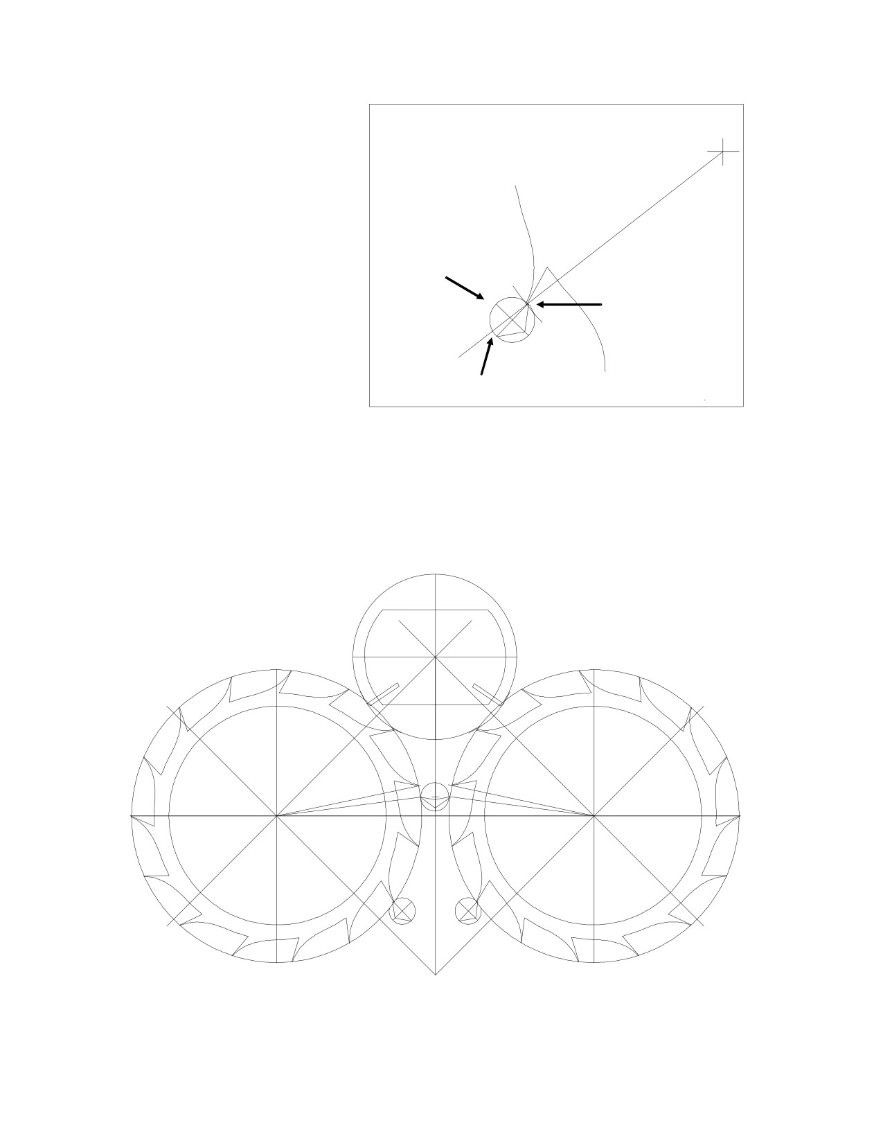
The lower locking
escape wheel
pallets have flat locking
faces, however. Rotate the
circle center
left escape wheel coun-
terclockwise by
4º and
lower
place one lower locking
pallet next to the escape
locking
tooth, below the pallet's
pallet
circle center, giving the
pallet
1º of lock and a
1º lock
draw angle of 8º. Rotate
the right escape wheel
clockwise by 4º and place
the other lower locking
8º draw
pallet next to the escape
tooth, as shown below, giving the pallet 1º of lock and a draw angle of 8º. Notice that
the sum of 10º for upper draw and 8º for lower draw gives 18º for total draw: this is
similar, if only slightly more than the 15º for draw designed into the Swiss Lever
pallets.
4º
4º
75
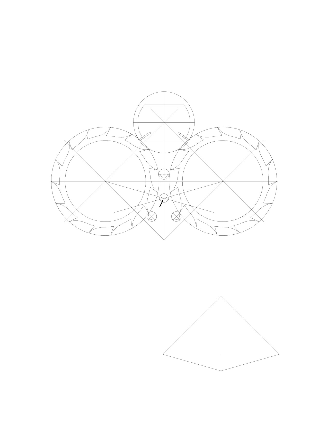
The locking pallets must be placed into position before you could locate their circle
center. The upper locking pallet lies 7º above the horizontal line. The lower locking pallets
each lie 38º below the horizontal line, so there are 45º between the upper and lower
pallets. Place the locking pallet's circle center 16º below the horizontal line, as shown by
the point where lines (10) and (11) intersect. The axis of rotation is important because the
displacement of each pallet should be the same during rotation.
16º
16º
(10)
(11)
locking
pallet
circle center
Before drawing the roller jewel that moves the locking pallets from side to side, you
need to find the distance from the roller jewel's circle center to the locking pallets' circle
center. I will call this distance "D."
D = L + 3.25
= (3.25 tan 16) + 3.25
3.25"
= 4.182 inches
45º
3.25"
3.25"
45º
16º
16º
L
76
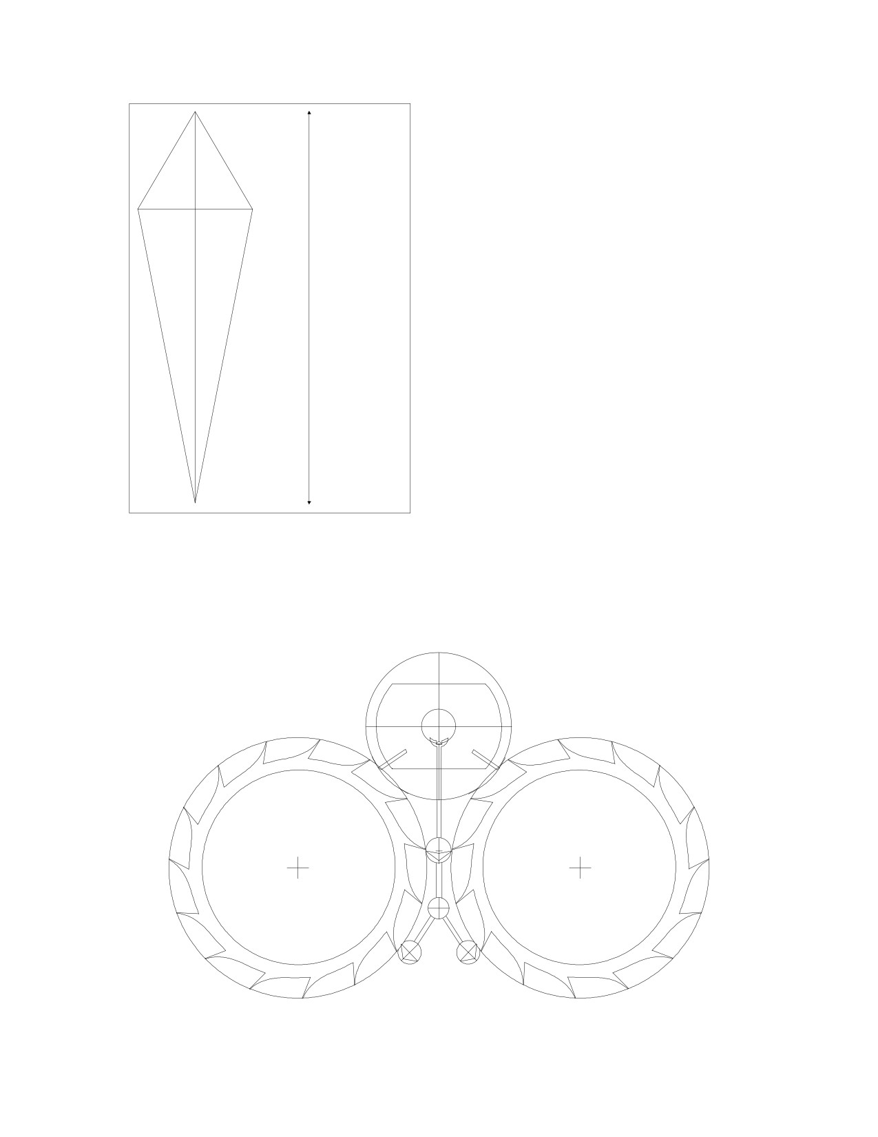
R will be the roller jewel's circle radius.
30º
30º
R sin 30 = G sin 3
(i)
R
E
0.5 R = 0.052 G
R = 0.105 G
F
R cos 30 + G cos 3 = 4.182
(ii)
D= E + F
= 4.182"
0.866 R + 0.999 G = 4.182
G
0.866 (0.105 G) + 0.999 G = 1.089 G = 4.182
3º
3º
G = 3.839
R = 3.839 x 0.105 = 0.402
(3.839 + 0.403) - 4.182 = 0.060
Draw the roller jewel's circle with a radius of 0.402 inches, and place it such that its
center lies on the center of the impulse pallet's circle. Draw the pallet fork with a radius of
3.839 inches from the locking pallets' circle center to the entrance corner of the fork horn:
the roller jewel would have a depth of 0.06 inches inside the pallet fork. I have not
included the locking pallets' circle in this drawing, but it would be needed for a simulation.
77
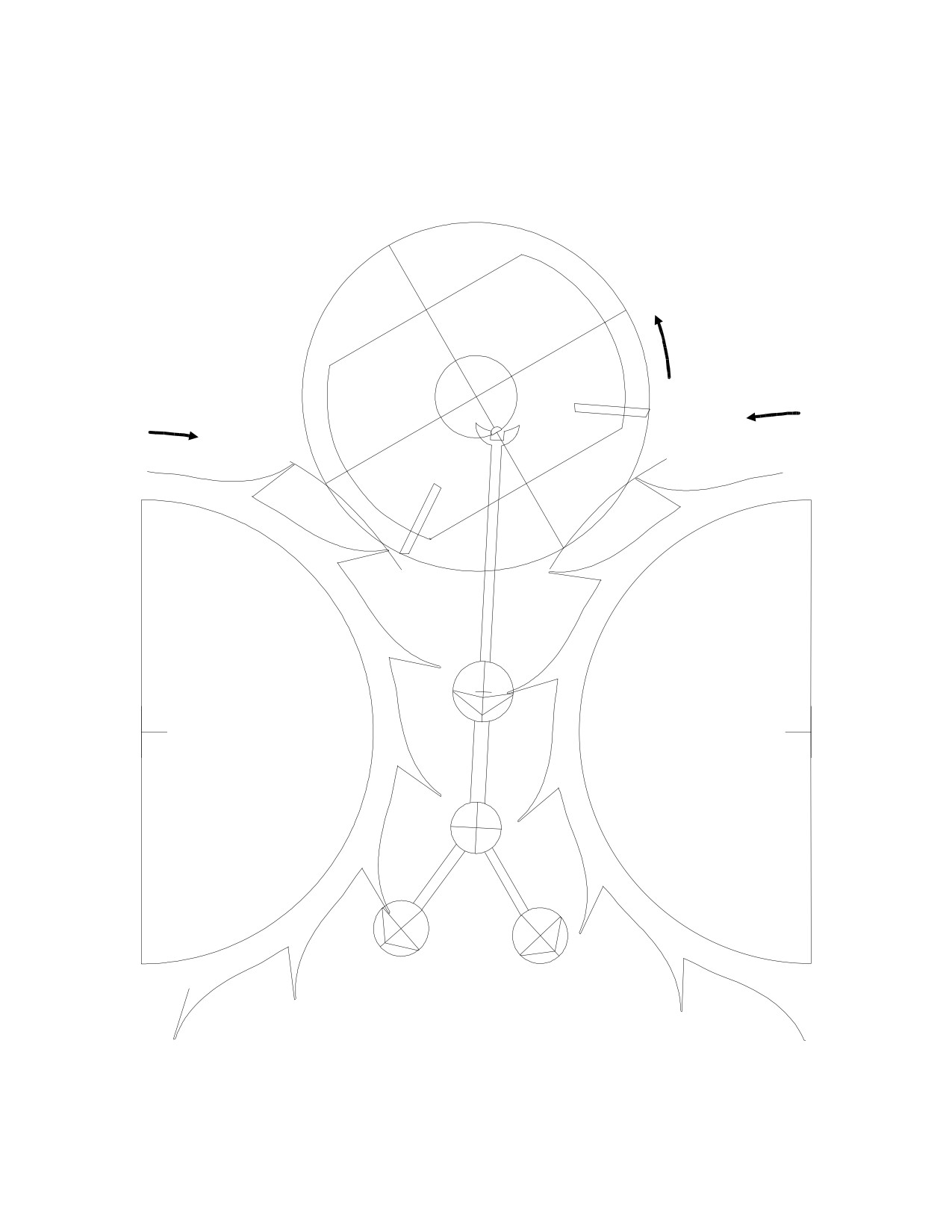
In this drawing, I have rotated the locking pallets clockwise by 3º and the impulse
pallet / roller table assembly counterclockwise by 30º. The left escape wheel has just been
released by the impulse pallet and is detained by a lower locking pallet. The right escape
wheel is detained by the upper locking pallet.
78

The drawing on the previous page reveals how complicated the design is. Notice how
the escape wheel and the impulse pallet appear to roll together, instead of sliding across
one another, and therefore why the escape wheels and the pallets need not be lubricated.
There are several differences between my drawing and the original specifications. I
made these changes in order to enhance the actions of the escapement during the simula-
tion. The gap between the escape wheels was not drawn in proportion to the original, but
the only effects this had were to change the impulse pallet's circle radius and the diameter
of the upper locking pallet. The convenience of using the gap of half an inch, in allowing
me to use the "snap to grid" function in the computer's software, outweighed the compul-
sion to draw it as closely to the original as possible. Furthermore, I chose an angle of 60º
for the rotation of the roller jewel during engagement with the pallet fork. The original
design called for 24º, but increasing the angle also increases the depth of the roller jewel
inside the fork: by exaggerating the actions of the escapement, the actions become more
easily visible during the simulation. Other side effects of increasing this angle from 24º to
60º are that the pallet fork becomes longer and the roller jewel's circle radius becomes
smaller by half. The depth increases by a factor of three.
This example demonstrates how creating your own drawings would allow you to
change the variables and observe the consequences. The idea is not necessarily to create
the drawing as closely to the original specifications as possible, but rather to make changes
and to experiment. You may be able to improve a design or even invent an all-original de-
sign.
22: The Double Roller.
In this chapter, we will design the pallet fork and the double roller for the last draw-
ing of the Swiss Lever Escapement in Chapter 15. Once the drawing with the theoretically
correct impulse face angle of 45º is completed, it must be modified slightly to correct the
1º out-of-angle condition, which could be corrected in two ways. The fork and roller table
could be rotated together by 0.5º using the pallet circle center as the center of rotation.
The second method involves changing the angles of the impulse faces to compensate. If
these angles were changed from 45º to 49º, the amount of lift of each pallet during impulse
could be equalized (though there would be a small efficiency loss of 0.5%):
79
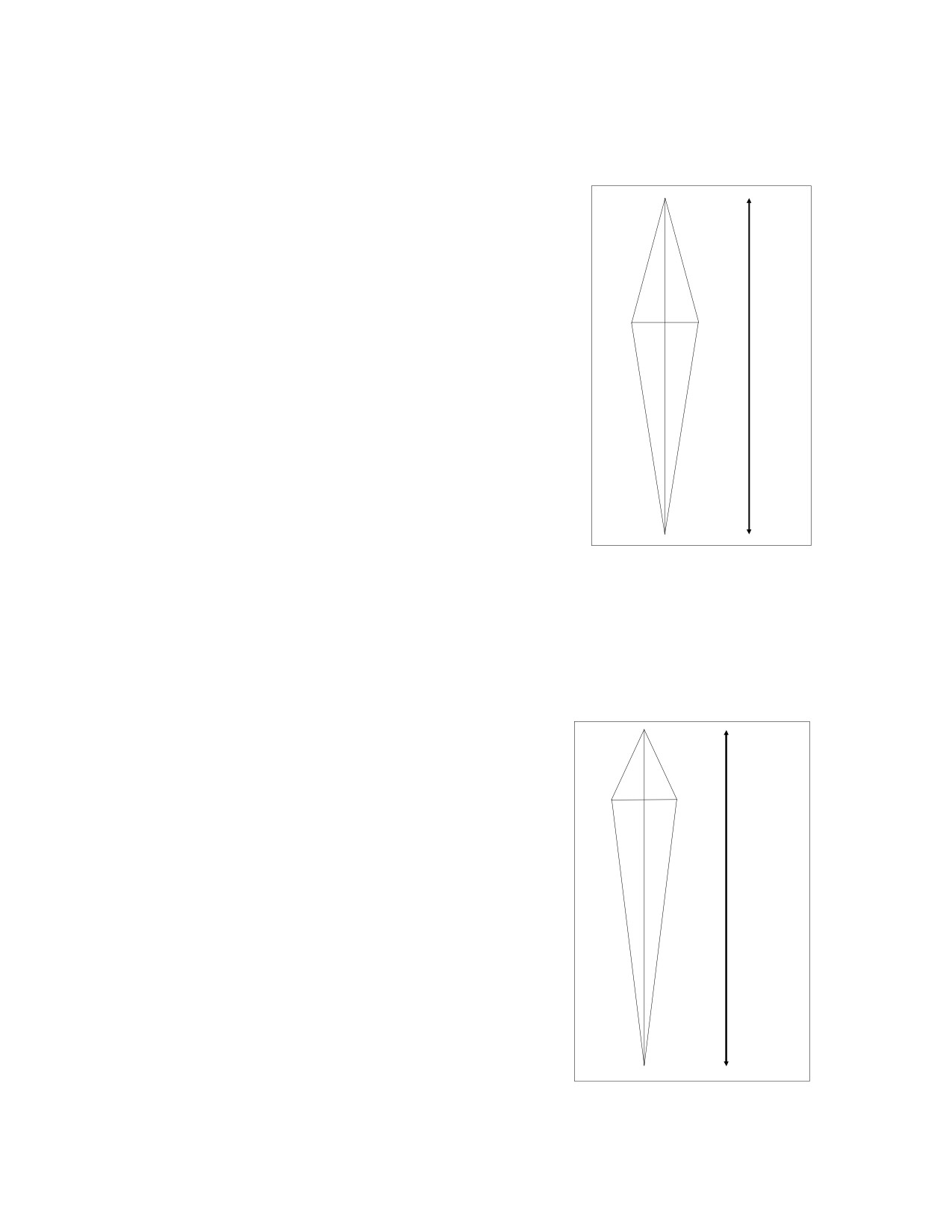
This was not mentioned in Chapter 15 in order to focus attention upon the need to maxi-
mize the efficiency of the impulse face angles. The result is two identical pallets with im-
pulse face angles as close to 45º as possible.
In the drawing, the pallets rotate by 18º in every
beat. If the pallet fork were three inches long and it
were assumed to rotate by 26º in every beat while in
contact with the roller jewel (in order to create plenty
15º
15º
of depthing for the simulation), and the roller jewel
X
X
were assumed to rotate by 30º, we could draw these
Y
triangles, which would be used to calculate the roller
T =
jewel's circle radius (X).
Y + Z
Z
X = 3 sin 13 / sin 15 = 2.607"
3"
3"
13º
13º
The distance between the pallet's circle center and
the roller jewel's circle center is given by T:
T = Y + Z = X cos 15 + 3 cos 13
T = 2.519 + 2.923 = 5.442"
Draw a pallet fork with a distance of 3 inches from the pallet's circle center to the
edge of the fork horn. Draw a roller jewel in a circle with a radius of 2.607 inches and
place it at a distance of 5.442 inches from the pallet's circle center.
The double roller has two roller tables, the larger one for the roller jewel and the
smaller one for the safety action. You need to find what dimensions the smaller table
needs to have to ensure proper safety action.
B sin 25 = C sin 9
(i)
B
25º
25º
B
B = 0.370 C
M
B cos 25 + C cos 9 = 5.442
(ii)
N
T =
M + N
(0.370 C) x 0.906 + 0.990 C = 1.323 C = 5.442
C
C
= 5.442"
9º
9º
C = 4.113
B = 0.370 x 4.113 = 1.522
B + C - T = depth = 1.522 + 4.113 - 5.442 = 0.192"
80
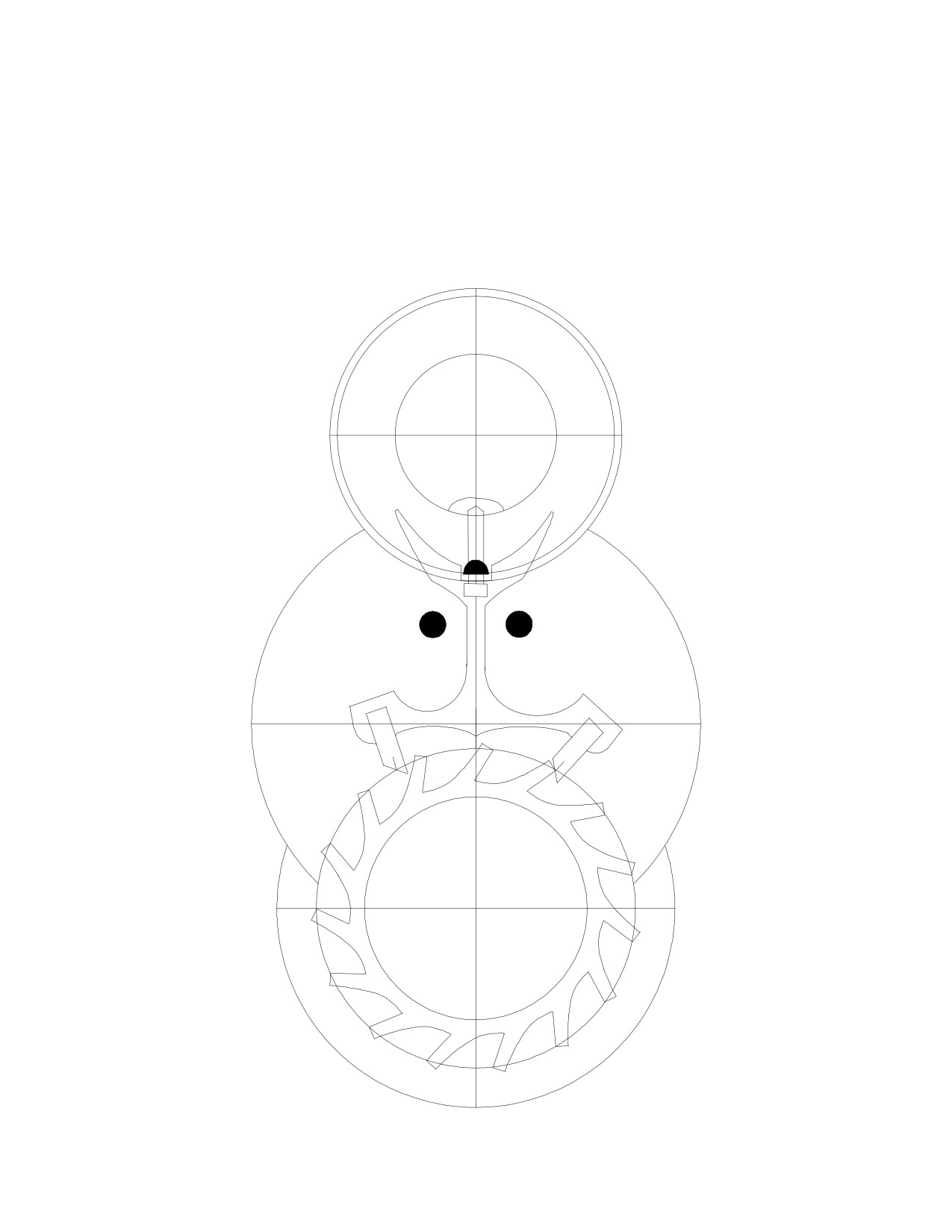
Draw a small roller table with a radius of 1.522 inches and center it inside the roller
jewel's circle. Draw the guard pin with a radius of 4.113 inches from the pallet's circle
center. Draw a notch in the smaller roller table that would allow the guard pin to clear it
because the latter would have a depth of 0.192 inches.
To place the banking pins, rotate the pallets by 9º from the vertical position, or until
the pallet has just released the escape tooth, plus 2º extra for slide, for a total of 11º. Place
a small circle next to the pallet fork in an appropriate position. Repeat on the other side.
81
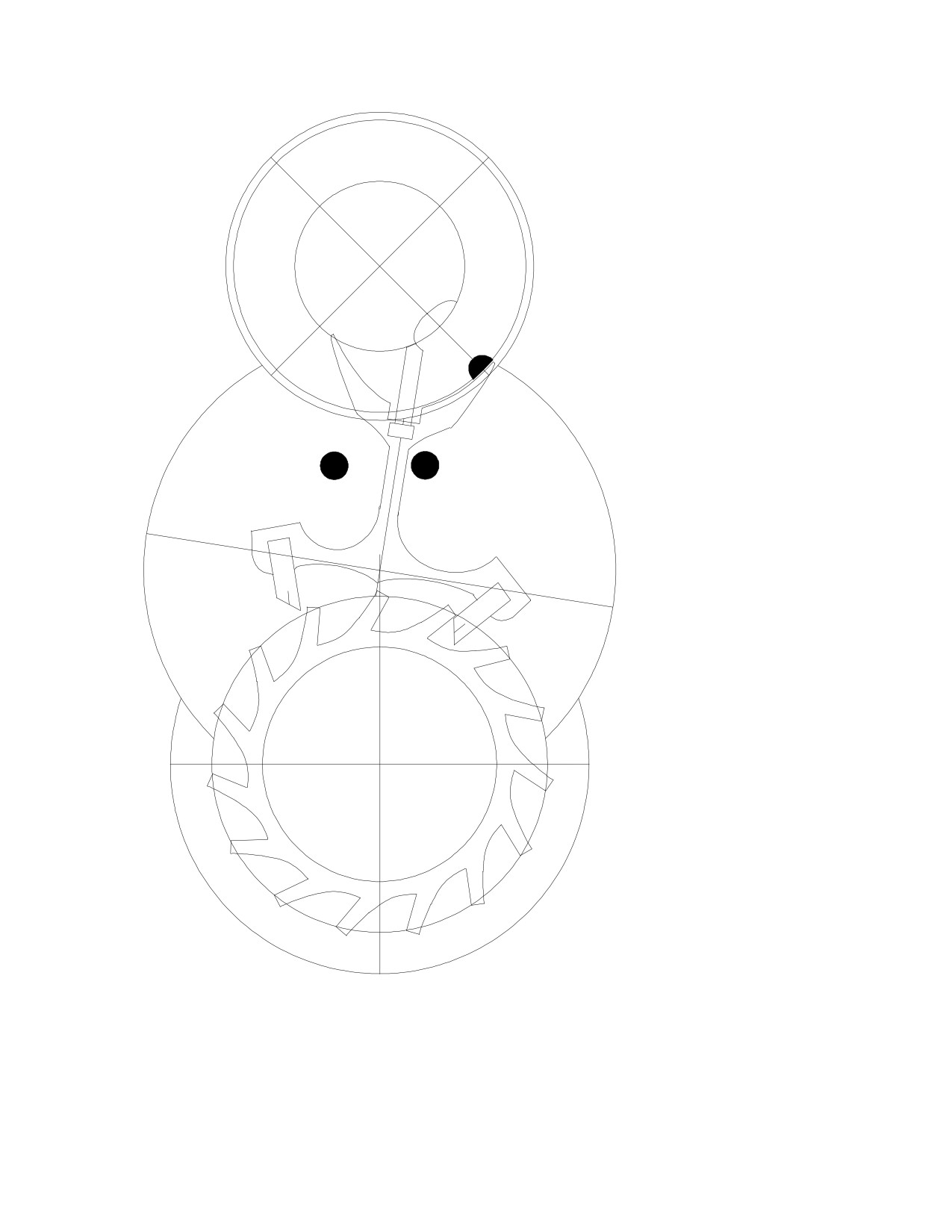
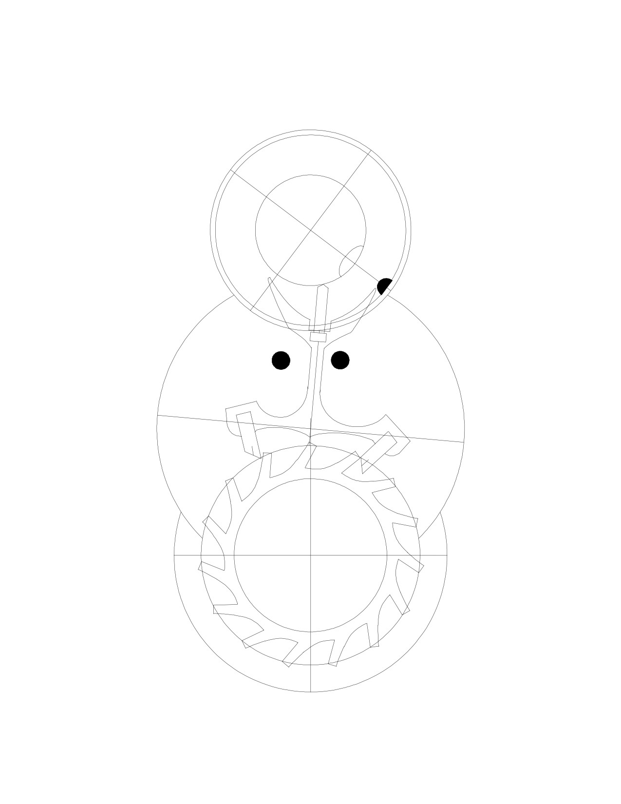
Rotate the pallets
until a tooth is re-
leased: this is the
"drop-lock position."
Rotate the roller table
until the safety notch is
just beyond the guard
pin, which appears to
be pressed against the
safety roller. Draw the
fork horn just outside
the path of the roller
jewel, and extending to
the jewel's other side,
as shown. This design
prevents premature un-
locking. Repeat on the
other side.
The fork rotates
by 18º in each direction
while the guard finger
is in the safety notch.
The fork also rotates
by 18º in each beat.
This way there is lock
whenever the guard
finger is against the
safety roller: if there
were no lock, there
would be no draw to
keep the guard finger
away from the safety
roller.
There is also a
small gap between the
fork and the banking
pin. This slide is neces-
sary to keep the guard
finger away from the
roller table. It also cre-
ates "fork horn freedom," which is the freedom of movement the fork has between the
roller jewel and the banking pin in this position, but notice that the guard finger prevents
the fork horn from touching the roller jewel at this point.
82
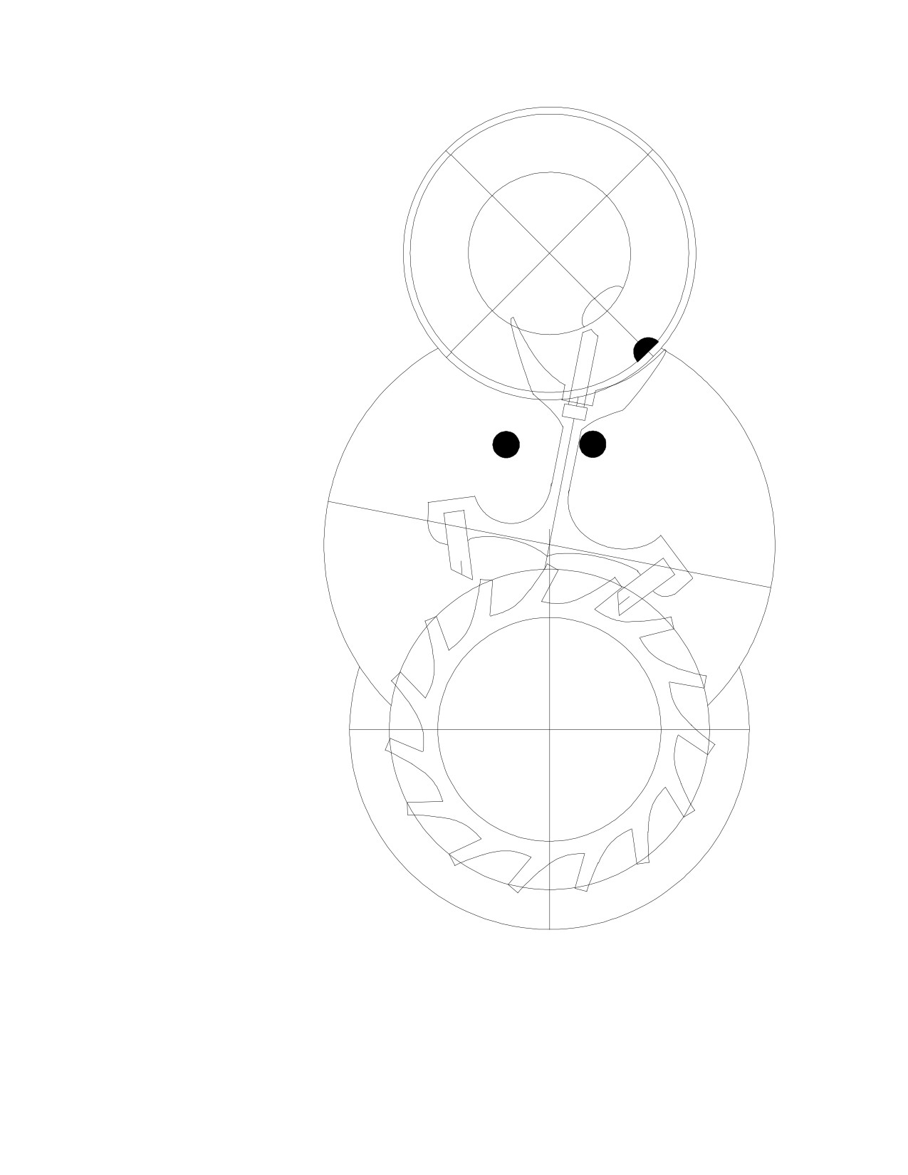
Rotate the pallets
by 2º further, until the
fork is pressed against
the banking pin. By in-
creasing the angle that
the fork is in contact
with the roller jewel
during rotation from
18º to 26º, you create
depthing to make sure
that, when the roller
jewel returns to unlock
the pallets, the roller
jewel would engage the
fork below its entrance
corner. This is the same
as making the fork
longer: if the fork were
too short, there may
not
be
enough
depth-ing.
If the guard finger
were too short, the fork
horn may get in the
way of the roller jewel,
and overbanking may
occur. Guard finger
freedom would be
increased, and if it
increased to the point
where the pallet were
allowed to unlock the
tooth, there would be
binding because the
guard pin would be
pressed against the
roller table as the es-
cape tooth pushes on
the pallet's impulse
face. Conversely, if the
guard finger were too long, there would be no gap between the guard finger and the safety
roller when the fork is pressed against the banking pin. This gap is called "guard finger
freedom."
83
In this drawing, the guard pin is too short. The escape tooth is pressing on the pal-
let's impulse face as the guard pin is pressed against the safety roller, causing severe fric-
tional losses. The fork horn is blocking the path of the roller jewel.
84
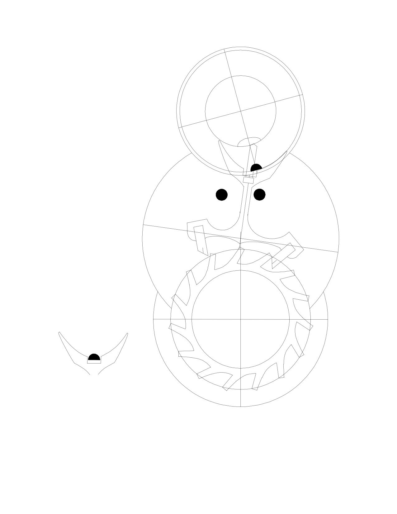
If the pallet unlocked
prematurely, just before
the roller jewel were to
begin to unlock it,
binding might occur.
There needs to be
enough lock so that
when the fork horn is
pressed against the
roller jewel before it
could completely enter
the fork slot, the pallet
does not unlock the es-
cape tooth. There also
needs to be some slot
corner freedom, or the
shake of the fork be-
tween the banking pin
and the roller jewel in
this position: here the
guard finger could enter
the safety notch and so
could not prevent pre-
mature unlocking, so
this position must be
checked very carefully.
The fork slot must
be slightly wider than
the width of the roller
jewel:
It should be clear
that with the freedom of
the roller jewel, the slot
corner freedom, the fork horn freedom, the guard finger freedom, and the side-shake of
the pivots in the jewels of the escape wheel, the pallet fork and the balance wheel, there
needs to be enough lock in the drop-lock position to prevent unlocking while the
parameters of these variables are tested. There also needs to be enough depthing of the
roller jewel in the fork slot in case the slide needs to be increased to ensure enough guard
pin shake.
85
The most important advantage of the double roller over the single roller is the ability
to increase the depth of engagement of the guard finger into the safety roller. Increasing
the depth reduces the likelihood that the pallet fork might accidentally move across to the
wrong side.
Lock and slide and the angle of the locking face together result in the small binding
action that keeps the guard finger away from the safety roller after each beat, a binding
action that is referred to as "draw." If the design had insufficient draw, consider what
would happen if the guard pin rubbed against the roller table.
If the guard pin rubbed against the safety roller on
the side, the oscillation of the balance wheel would be
interfered with, and the symmetry of the action of the
balance wheel would be altered, affecting the timekeep-
ing.
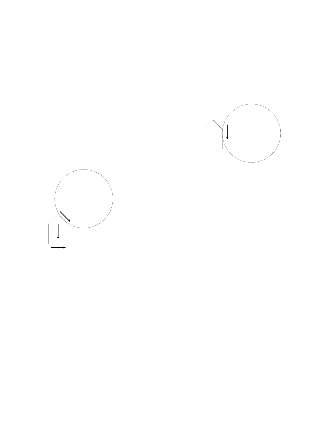
The power loss increases dramatically if the guard pin
rubs the safety roller from a different angle. Here, the safety
roller exerts a force (1) upon the guard pin that could be seen
as pushing the pin towards the pallets, shown by arrow (2),
(1)
and as pushing the pin towards the other side, shown by arrow
(3). Arrow (3) shows that this arrangement has a binding ef-
fect when the guard pin is pressed against the roller table. The
(2)
drawings on pages 82 and 84 reveal a similar binding effect,
and the latter is compounded by the escape tooth pushing on
(3)
the pallet's impulse face. The banking pins are adjusted wide
enough to create enough draw to keep the guard finger away from the safety roller, and
far enough away to reduce the likelihood that the finger might touch the roller if the watch
were jolted.
Look back at the chapter concerning the Duplex escapement to see how the relation-
ship between the escape wheel's locking tooth and the locking jewel would result in a
similar binding effect. The same binding effect could be found in the Cylinder escape-
ment.
It is naturally assumed that the timepiece should be adjusted to maximize efficiency,
but there is one criterion that is more important than efficiency and for which some effi-
ciency should be compromised: symmetry of action. A fine watch might be adjusted for
maximum efficiency by adjusting for only a very small amount of drop-lock and a very
small amount of run to the banking, in order to minimize the power losses caused by draw.
The watch may run very well on the timing machine, keeping consistent time in all posi-
tions. However, when worn on the wrist, this watch would become erratic, particularly if
the owner were very active. This is because the movements on the wrist would cause the
fork to interfere with the movement of the balance wheel, even if only occasionally and
only momentarily. The watch may otherwise appear to run well. If the lock and slide were
86

increased slightly to ensure better action, the watch would be a more consistent time-
keeper, even though a small amount of efficiency may be compromised in the adjustments.
The power lost in unlocking (caused by draw) should not be seen as wasted because draw
serves such an important function. The locking angle, the drop-lock and the run to the
banking should be the same on both sides, in order for the forces of action and reaction to
be symmetrical on both sides.
You could use computer simulations to see the effects of problems caused not only by
maladjustment but also by design defects. For example, you could observe the action of an
eccentric escape wheel, or what would happen if you installed an escape wheel that is over
or undersized. You could observe the effects of having the wrong pallets, too thick or too
thin, or the effect of having one jewel set further out than the other, resulting in the fork
being "out of angle." What would happen to the adjustments if the temperature changed
and the metals in the watch expanded or contracted slightly? By creating your own draw-
ings and experimenting with changes in the variables, you will increase your understanding
of escapements considerably, and this knowledge will add to your skills at the bench.
Please visit my Horology Website on the following servers:
If you collect watches and clocks, be sure to visit my other website about watches,
The watch website has information about what to look out for as a collector of watches
and clocks, and a large photo gallery of watch mechanisms. If you have any difficulties
with the main website, you could try one of the others, which all have the same content.