CLOCK AND WATCH ESCAPEMENT MECHANICS (1997) - page 1
Section 1: Clock Escapements.
1: Efficiency and Power Losses.
Page 4
2: Drawing an Escape Wheel.
5
3: Drawing the Graham Pallets.
6
4: The Graham Explained.
8
5: The Importance of the Simulation.
11
6: The Recoil Escapements.
16
7: The Brocot Escapement.
18
8: The Pin Wheel Escapement.
19
9: Other Design Considerations.
20
10: The Graham Reconsidered.
22
11: Efficiency in Numbers.
23
The first nine chapters are explained without math. These chapters are less
complicated, and they introduce the reader to the logic behind the drawing techniques, so
as to serve the needs of those who want to learn about escapements but would not be
drawing them on their own computers. The tenth chapter explains the math behind the
previous chapters. This way the reader has the option whether or not to become involved
with the math.
References:
Britten's Watch & Clock Maker's Handbook, Dictionary and Guide (1978 Edition).
Donald de Carle:
Watch and Clock Encyclopedia (1977 Edition).
Henry B. Fried:
The Watch Escapement (1974 Edition).
1
Section 2: Watch Escapements.
12: Drawing the Club-Tooth Escape Wheel.
Page 41
13: Drawing the Pallets.
44
14: Changing the Design.
50
15: Improving the Design.
53
16: The English Lever.
57
17: The Pin Pallet Escapement.
60
18: The Cylinder Escapement.
61
19: The Duplex Escapement.
63
20: The Chronometer Escapement.
67
21: Daniel's Independent Double-Wheel Escapement.
72
22: The Double-Roller.
79
Chapters 12 to 18 are similarly presented in order to introduce the reader to the
logic behind the drawings, though these drawings are more involved and require some
understanding of watch theory, such as lock, drop, draw, and impulse. Chapter 19 and
beyond become more involved with the math that is required to create the drawings. The
reader who does not want to become involved with the math could benefit from the logic
of the latter chapters by passing over the math.
I would like to thank the following for their invaluable assistance and encour-
agement:
Daniel Henderson
Cecil Mulholland
Roy Hovey
Steve Conover
Nino Gonzales
Harry and Sue Wysong
2
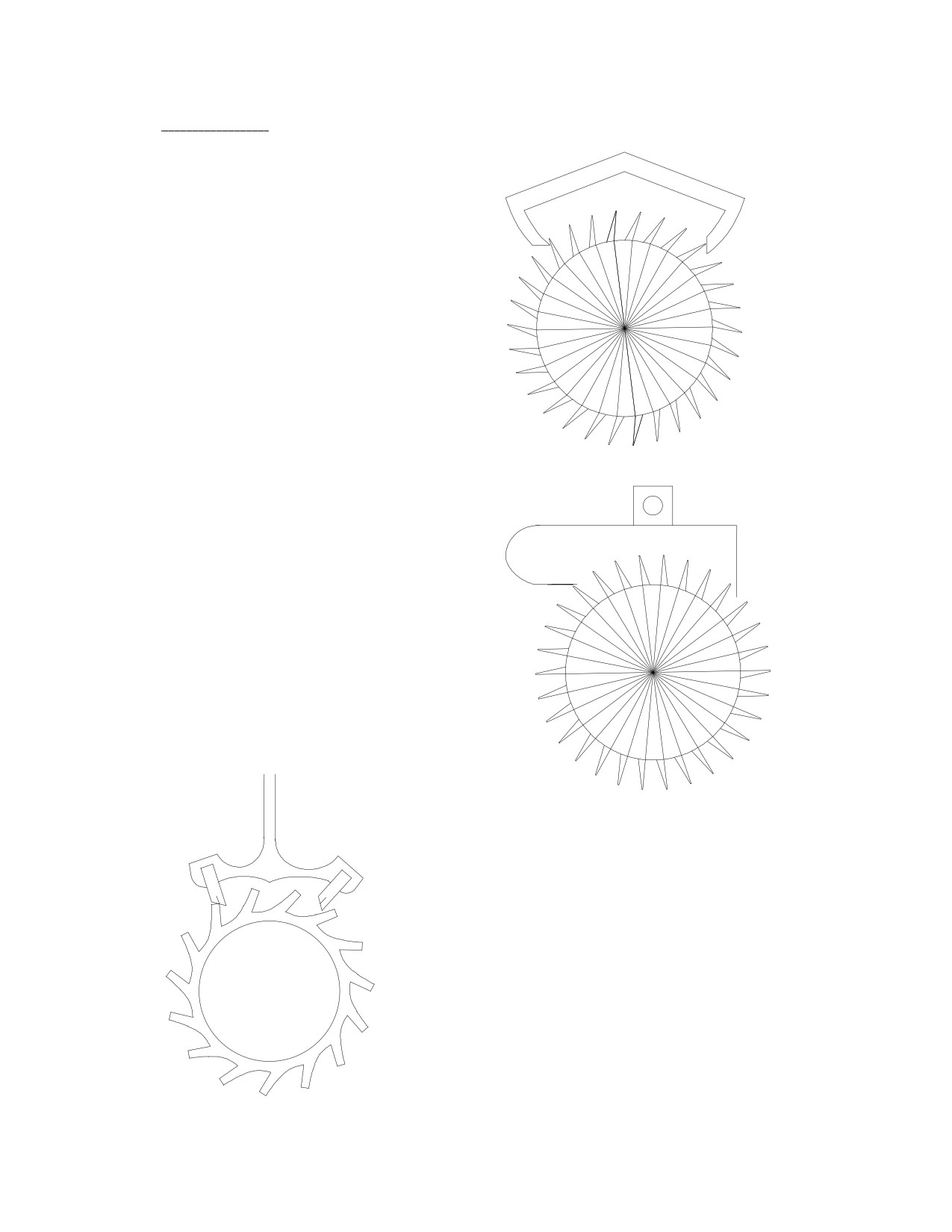
Introduction.
Graham escapement
Discover how much more there is
to know about escapements by creat-
ing your own drawings. The purpose
of this project is to introduce the
reader, whether professional or hob-
byist, to a hands-on method for draw-
ing a mechanical clock or watch es-
capement. While it is more obvious
that a manufacturer needs to know
how to design a pallet, the repairman
could do a better repair with an im-
proved understanding of design the-
ory. The ability to draw an escape-
ment enables one to experiment more
easily with the effects of changing the
variables and to compare different
Strip-pallet recoil
types of escapements, their similari-
ties and differences.
The most important reason for
careful attention to design is effi-
ciency. The escapements most fre-
quently encountered at the bench are
the Recoil, the Graham
(or
dead-beat), and the Swiss Lever.
These all have efficiencies below
50%. This means that more than half
the power is lost in the escapement
alone, after all the power losses in the
gear train.
modern
Swiss
Lever
These drawings are not dissimilar to what I
have seen in escapement literature. They do not
reveal the methods by which they were de-
signed, why the lines and curves are positioned
so. If these drawings ignite your curiosity, this
project is for you.
3
1: Efficiency and Power Losses.
A clock is usually taken to the shop for repair because the clock fails to keep
running. It runs for a while and stops because not enough power reaches the pendulum to
keep it running. One way to get it running is to double the weight, but this causes enor-
mous wear and consequent damage in the long run. The other way is to overhaul the
clock. The job of the repairman is to do whatever is necessary to minimize the power
losses between the weight and the pendulum. The clock is cleaned. Pivots are polished.
Worn bushings are replaced. Adjustments are made to the escapement to improve its
action. The clock is carefully lubricated. Other repairs are made as needed. These all
have the ultimate goal of reducing power losses.
There are two kinds of power losses in a clock: frictional losses and losses caused by
the action of the escapement (which result in additional frictional losses). Frictional
losses are easily understood. The lubricant has failed, causing drag. The bushings are
worn, so the gear and pinion teeth grind together. The pivots are scored, causing
frictional losses from rough surfaces. Dirt particles become imbedded in the worn
bushing, causing binding of the pivot, and so on.
Power losses caused by the action of the escapement are less obvious. The following
reasons are explained in detail in subsequent chapters. If the escape wheel rotates clock-
wise, the force it exerts on the pallet would be in a different direction to that of the
pallet's movement. The greater the angle between the two directions, the greater the loss
of power as it is transferred from the escape wheel to the pallet. Consider that the pallets
rotate clockwise as the escape tooth pushes on the entry pallet, and counterclockwise as
the tooth pushes on the exit pallet, yet the escape wheel continues to rotate in the same
clockwise direction.
As the escape tooth pushes on the pallet, the tooth exerts a force in the
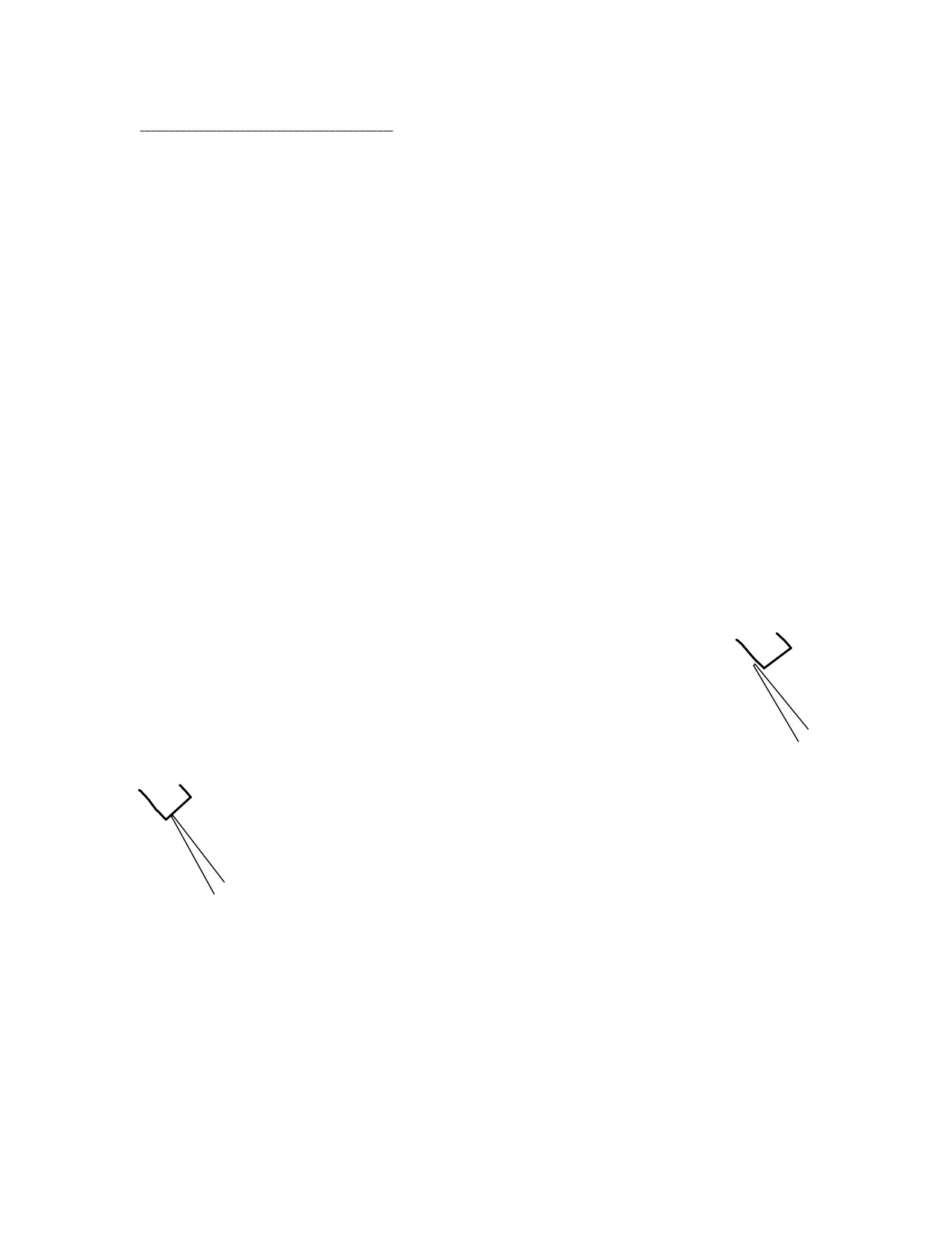
same direction as its direction of travel at that point. If the point of contact
on the pallet were at 90º to this direction, such as on the locking face of the
Graham pallet, the escape tooth would not move forwards and no power
would be transferred to the pallet.
If the point of contact were in the same direction as the escape tooth,
so that the pallet's impulse face were parallel to the path of the tooth, the
tooth would pass by freely and provide no impulse to the pallet.
No power is transferred to the pallet when the angle is 90º or 0º. An angle in
between is needed: the angle that maximizes the power transfer. Find what direction the
escape tooth is moving in as it passes over the pallet, and the direction of the pallet. Then
determine the direction in which the pallet should receive power from the tooth. The di-
rection should be half way between those of the tooth and of the pallet. For maximum
efficiency, the pallet's impulse face needs to be at right angles (90º) to this direction.
If the angle between the directions of the tooth and of the pallet were 90º, the maxi-
mum achievable efficiency would be only 50%. This is achieved when the impulse face's
4
angle is at 45º to the direction of the tooth's travel. If the impulse face's angle were 25º,
the efficiency would be merely 38%. That is a 24% power loss caused by improper de-
sign. If the repairman could see this, he could adjust the impulse face's angle more
closely to what it should be, and maximize the pallet's efficiency, given the original
design he has to work with. Ideally, the impulse face's angle should be at 90º to the angle
half way between the directions of the tooth and of the pallet.
You may not find this easy to understand: power losses by escapement design are
less obvious. This will become clearer in the next chapters, as we draw the Graham
escapement. It should, however, have become clear to you how important the design of
the escapement is. I have seen clocks in which one pallet received a negligible impulse
from the escape wheel, so the maximum achievable efficiency was only 25%. Why
would they would not keep running?
2: Drawing an Escape Wheel.
I am currently using an IBM with Windows and a drawing program called Key-
Draw. If you have AutoCAD, you are well equipped. The most important features you
need are the ability to draw lines and circles on a grid, and the ability to rotate the lines
by angles that you determine. You may have a different method. This is just one way to
do it.
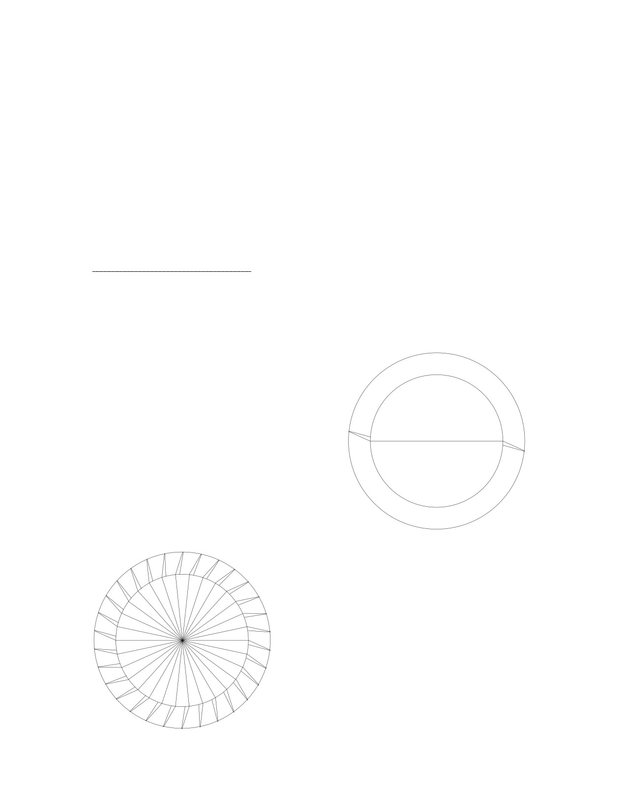
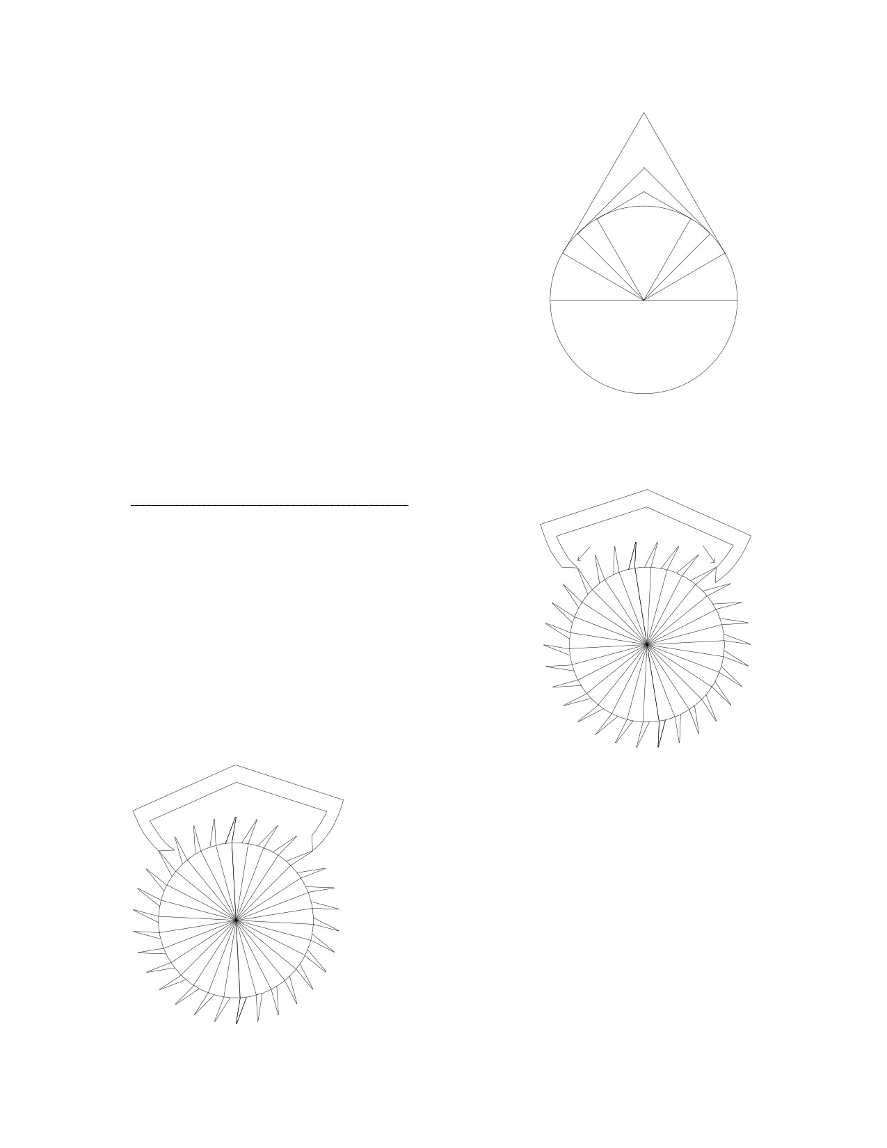
First, draw a large circle. A diameter of 6
inches worked well for me. Draw another
circle of 4.5 inch diameter and center it inside
the first. Draw a horizontal line across this
circle, bisecting it. Draw a tooth on one side
until you are satisfied: I chose a line at 15º and
another at 25º from horizontal, positioned to
fit, and with a small gap to allow for tooth
thickness. Duplicate, rotate, and place a tooth
on the other side. Your drawing should look
like this:
Move the inner circle outside. Group the
outer circle with the line and the two teeth,
duplicate and rotate by 12º. Duplicate the new
group and rotate it by 12º again. Repeat this
until you have thirty teeth. Ungroup all the
elements and remove the outer circles, one at a
time, until only one is left. Place the inner circle
in its original position, and group all the teeth
and circles. The reason for placing a tooth in a
circle before rotating is because the circle makes
the tooth rotate about the center of the circle, in
order to achieve the desired result.
5
Rotate the groups by 12º at a time because there are 360º in a full circle, so if you
want a 30 tooth circle: 360 / 30 = 12º. If you want a 48 tooth circle, divide 360 by 48 to
get 7.5º. Thus escape wheels with different numbers of teeth could easily be made.
Escape wheels with the teeth pointing in the other direction could be made by flipping
the image, or with teeth of different shapes, such as the club-tooth escape wheel in Swiss
watches.
3: Drawing the Graham Pallets.
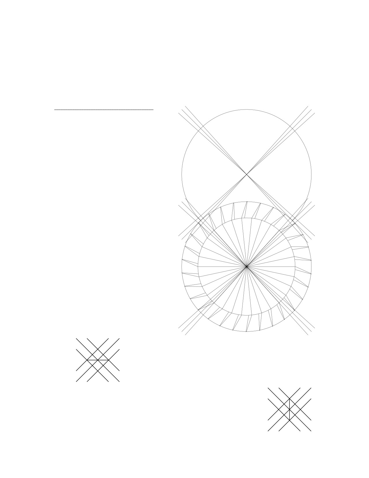
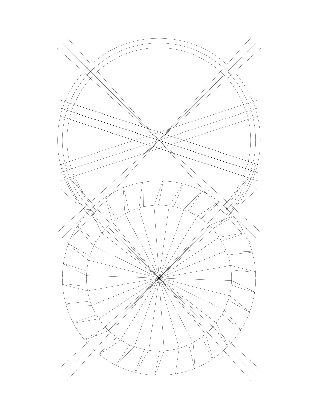
Over the escape wheel, draw
two radius lines at
90º to one
another. Draw two more lines at
90º to the radius lines and place
them at the edge of the circle. The
point where these new lines inter-
sect is the center of the pallet cir-
cle, the radius of which should
measure three inches. Draw the
pallet circle about this point. You
now have four radius lines. Draw
two more radius lines next to each
one, positioned at 3º on either side
of each. I chose to extend all the
radius lines:
Since the escape wheel rotates clockwise, the entry
pallet is on the left side of this drawing. Draw a horizontal
line between the three lines.
The exit pallet is on the right side: draw a vertical line
between the three lines there.
6
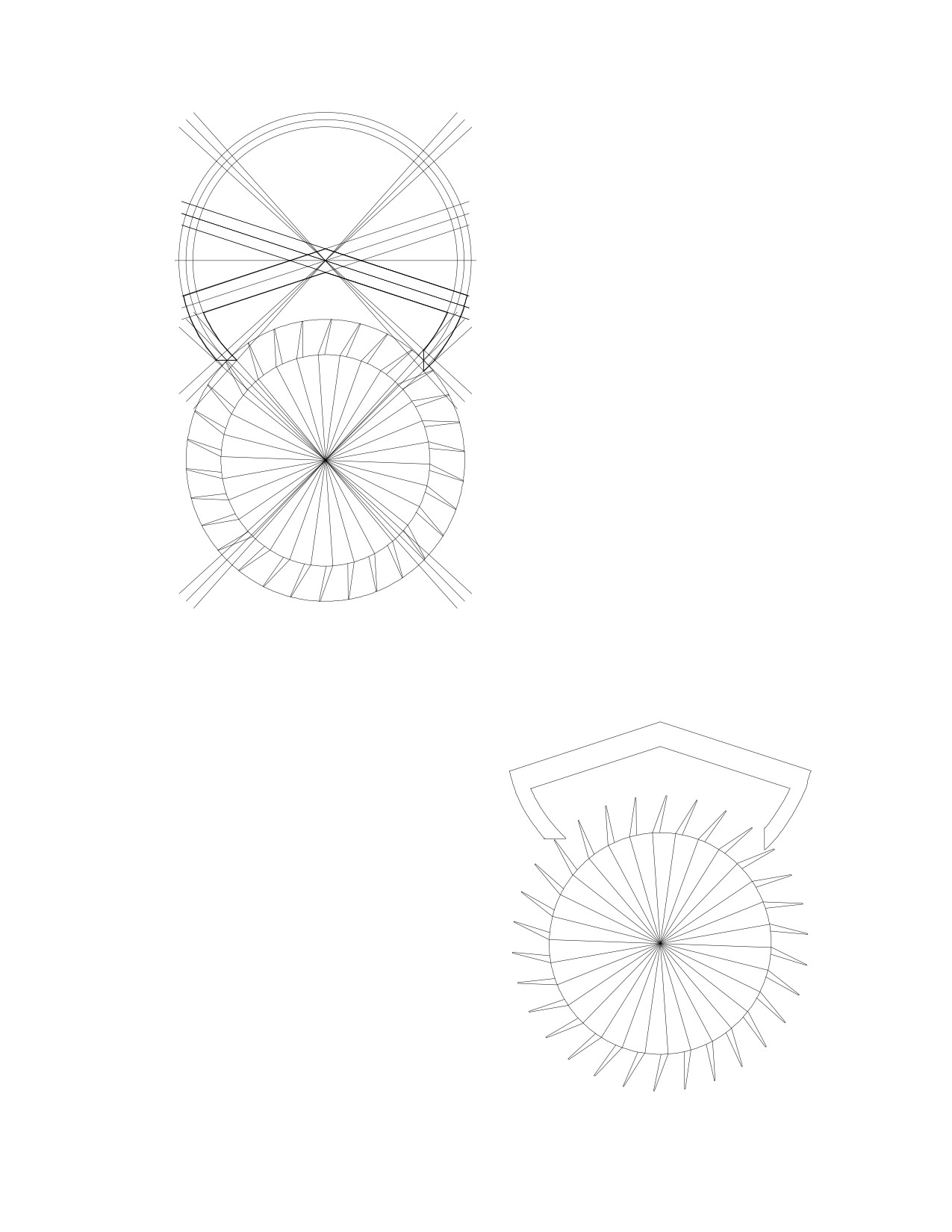
It is important to draw the locking
faces, which will consist of curves
drawn over circles, such as to preserve
the dead-beat nature of the design. Draw
two more pallet circles with diameters of
5.69 and 6.31 inches. Once these lines
have been completed, the rest of the
pallet could be drawn any way you wish.
I drew the this one by drawing a hori-
zontal line across the pallet circle, then
rotating it by
24º, duplicating it and
placing one line 0.25 inches above the
center line and the other 0.25 below. I
grouped these two lines, duplicated
them, flipped them horizontally, and
placed one pair on the other side.
Remove the excess lines to get the
result. This is the ideal Graham design as its
angles maximize the power transferred from
the escape wheel to the pallets.
7
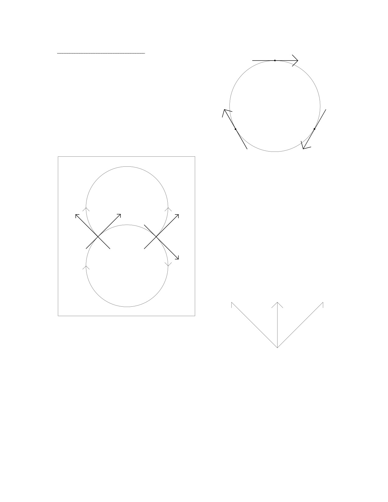
4: The Graham Explained.
As the escape wheel rotates, it exerts a
force upon anything it encounters in its path.
The direction of this force depends on what
point on the escape wheel the pallet is
located, as shown here: the arrows show the
different directions of force for three points
on the escape wheel.
NORTH
If the top of the page were North,
PALLETS
the escape wheel would push on the en-
try pallet towards the North-East. This
force has size and direction. I have la-
beled it 'Fe1,' or the force exerted by the
escape wheel. At this point, the pallet
Fe1
rotates clockwise: a force should push it
Fp1
Fp2
in a North-West direction, marked 'Fp1'
WEST
entry
side
exit
side
EAST
(force to pallet). The angle between Fe1
Fe2
and Fp1 is
90º. If a third line were
introduced, labeled 'Fi'
(force of
impulse), with an angle half way in
between, you could think of an impulse
force in that direction:
ESCAPE
Fi
WHEEL
Fp1
Fe1
SOUTH
We have Fi because a force cannot be rotated by 90º in the Graham escapement,
which is why no power is transferred to the pallet from the escape wheel when the
pallet's impulse face is at 90º or 0º to Fe. It could be rotated twice by 45º, though. Fi is at
90º to the impulse face's angle, so if the impulse face's angle were changed, Fi would
change. As Fe1 goes North-East, imagine that a portion of that force is received by the
impulse face at right angles to its angle: Fi due North. Then imagine that a portion of Fi
acts in a North-West direction, Fp1, to rotate the pallet. The portion of Fe1 not received
in Fi is lost, and so is the portion of Fi not received in Fp1, which means that power is
lost in each step.
8
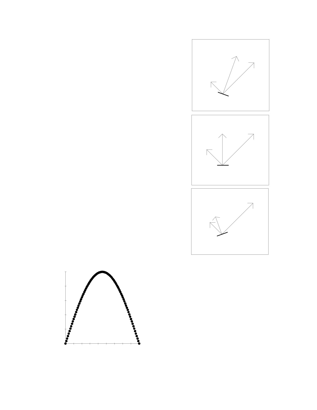
If the lines were drawn to scale, you could see
91%
how much power is lost. Scale drawings could be
Fi
100%
used to show the effect of angle on Fi and Fp:
Fe1
changing the angle of the impulse face has a
38%
dramatic effect on the force Fp1 that rotates the
Fp1
pallet, even though the angle between Fe1 and Fp1
25
remains unchanged at 90º. If the angle FeFi were
25º, the efficiency would be 38%.
impulse
face
71%
100%
Fi
Fe1
If the angle were 45º, the efficiency would be
50%
50%.
Fp1
45
impulse
face
100%
Fe1
If the angle were 65º, the efficiency would be
42%
38%.
Fi
38%
Fp1
65
impulse
face
50
%
e
40
f
f
30
i
c
The greatest efficiency is achieved
i
20
e
when the angle of Fi is half way between
n
those of Fe1 and Fp1.
10
c
y
0
0
10 20 30 40 50 60 70 80 90
angle between Fe and Fi
9
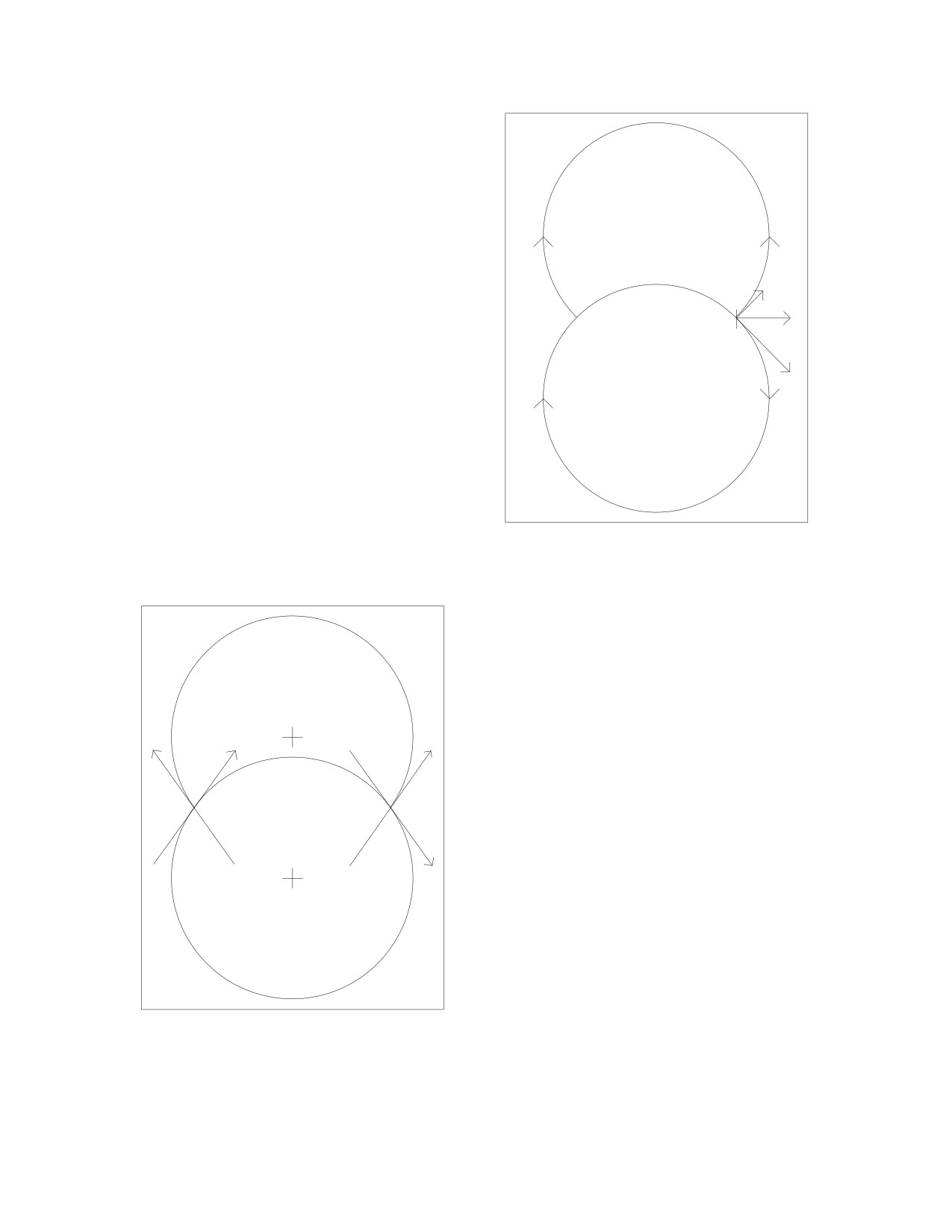
PALLETS
Fp2
On the exit side, Fe2 goes South-East
Fi
and Fp2 goes North-East. Since Fi should
impulse
face
go at an angle half way in between, Fi goes
Fe2
East:
ESCAPE
WHEEL
PALLETS
An angle of 90º between Fe and Fp is
Fp1
Fe1
Fp2
preferred because of symmetry: the angle
Fe1Fp1 plus the angle Fe2Fp2 always equals
<90º
more
180º. Therefore, if the angle Fe1Fp1 were
than
>90º
greater than 90º, the angle Fe2Fp2 would be
90º
less
less than
90º to the same extent. Or vice
than
90º
versa.
Fe2
ESCAPE
WHEEL
10
As the angle FeFp increases, the maximum
achievable efficiency decreases, so the smallest angle
possible is preferred. The loss of efficiency on one
side is equal to the gain in efficiency on the other
side, but there is no advantage in an unequal ar-
rangement. When the efficiencies are unequal, the
90
90
push the pendulum receives on one side is different
versus the other side, instead of the same. In the Gra-
ham escapement, therefore, the angle FeFp should be
90º because of symmetry. This is illustrated by the
following drawing, which should be familiar to many
clockmakers.
This approach could be used to determine the
distance between the escape circle center and the
pallets' circle center for the tooth span (the number
of teeth between the pallets) of your choice: choose a 4.5 tooth span for a wide pen-
dulum swing, or an 11.5 tooth span for a narrow swing. It is generally accepted that a
7.5 tooth span gives the most desirable results in practice for a 30 tooth escape wheel.
5: The Importance of the Simulation.
You need to simulate the action of the escape-
ment on a computer to determine if the drawing works
in practice, without having to make the parts first to
find out. I was able to rotate the escape wheel by one
degree at a time, and the pallet in the same manner, to
simulate the action in practice. There was binding
because there was no inside drop.
There was also no outside drop.
The creation of drop results in the escape tooth
landing on the pallet's impulse face, which causes
recoil action. In order to avoid this, the pallets must
be designed with impulse face angles that result in
lowered efficiency. See the drawing on the next
page. This is the modified Graham design as the
ideal design had to be modified before it could be
used in a simulation.
In theory, there should be 1º of lock and 1º of
drop. However, the simulation works better with 2º
of lock and drop.
11
12
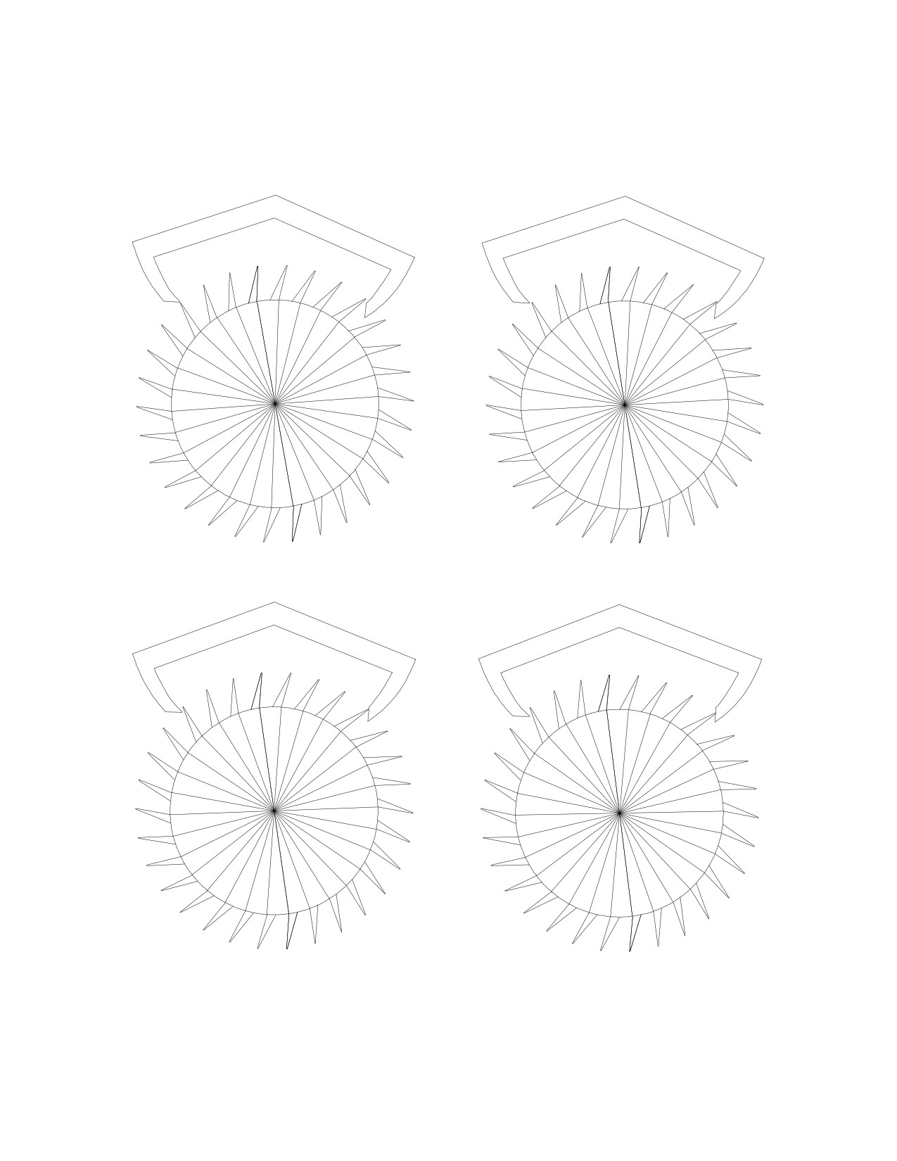
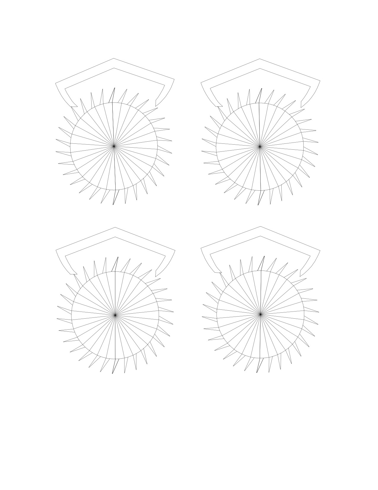
During the simulation, the escape wheel and the pallets are rotated by one degree at
a time in their respective directions.
1.
2.
3.
4.
13
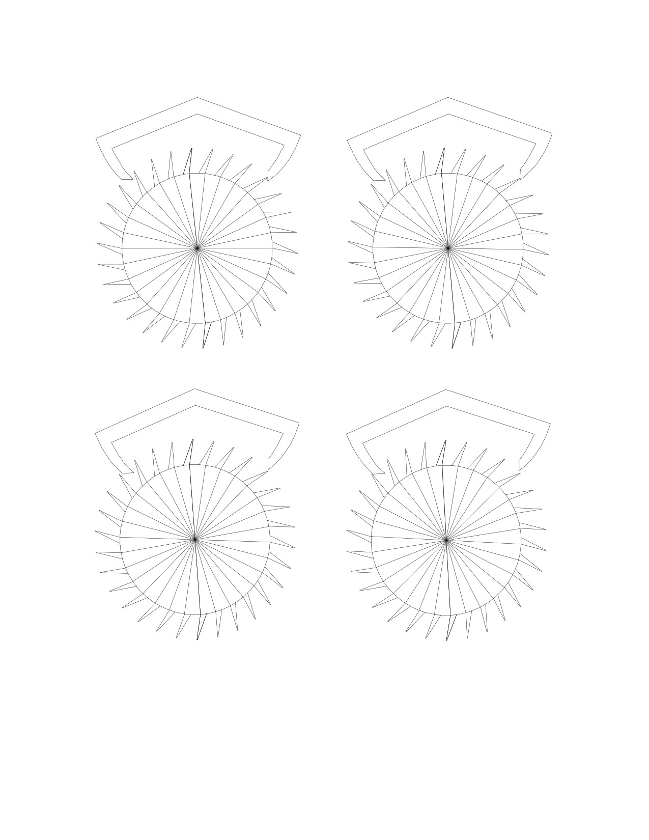
5.
6.
7.
8.
14
9.
10.
11.
12.
Be aware, when you prepare to do a simulation, that the group of lines comprising
the pallets and the escape wheel must be symmetrical about the point you intend to ro-
tate, because if the center of the group were not the same as the center of the pallets, for
example, then the rotation would not take place the way you want it to. Therefore, the
circles should be included in the groups being rotated, as shown in the drawing that
preceded the simulation.
15
6: The Recoil Escapements.
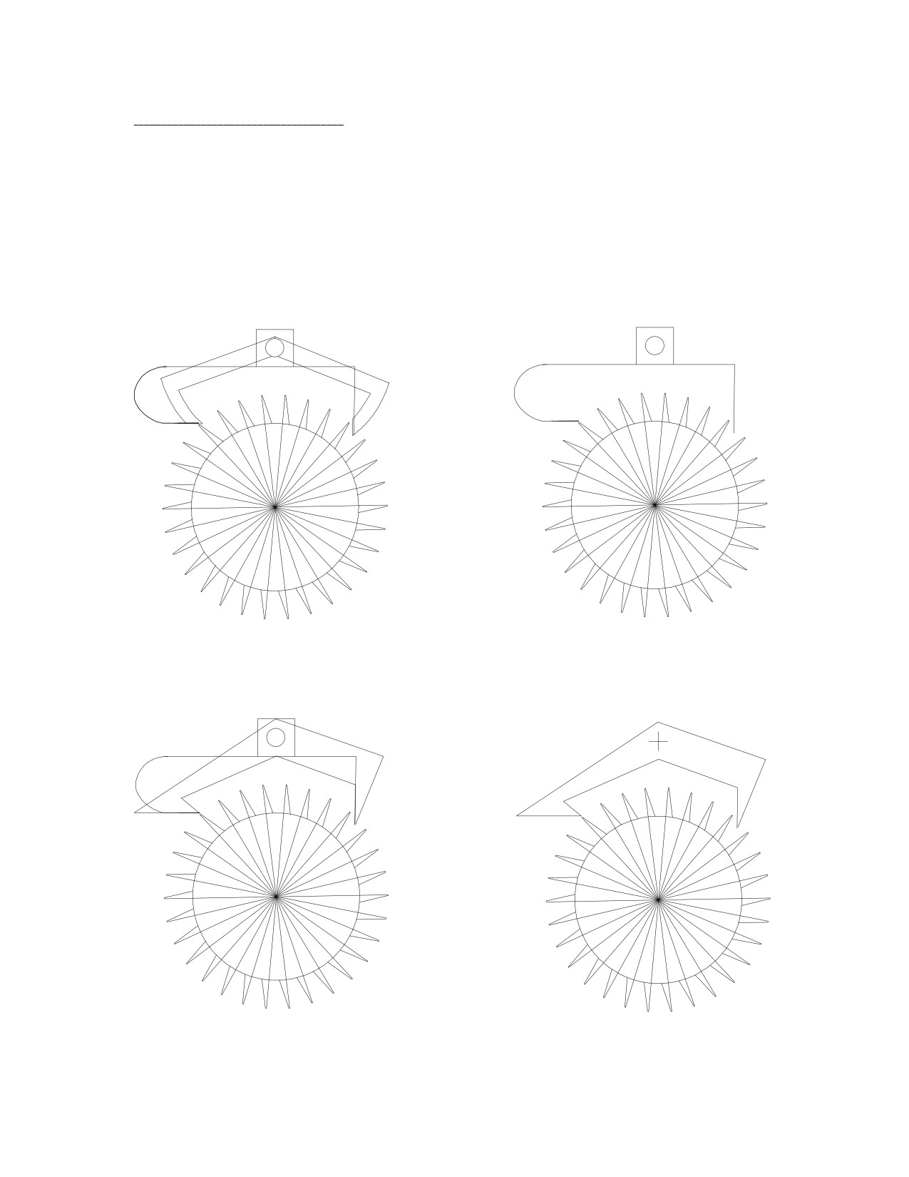
Once you have the Graham escapement drawings, drawing the recoil escapements is
easier because the images could be superimposed for reference.
With the recoil escapements, there is no need to adjust for lock, only drop. This
really simplifies the issue. Just create some inside and outside drop, and make sure that
the angle FeFi is 45º. Since no adjustment is made for lock, use the ideal Graham
drawing for reference. Shorten the entry pallet slightly and move the exit pallet slightly
outwards, parallel to the impulse face of the Graham exit pallet:
Notice that the escape wheel has been changed.
Once the Graham is removed:
Now for another recoil pallet, this time superimposing one recoil pallet over another:
16
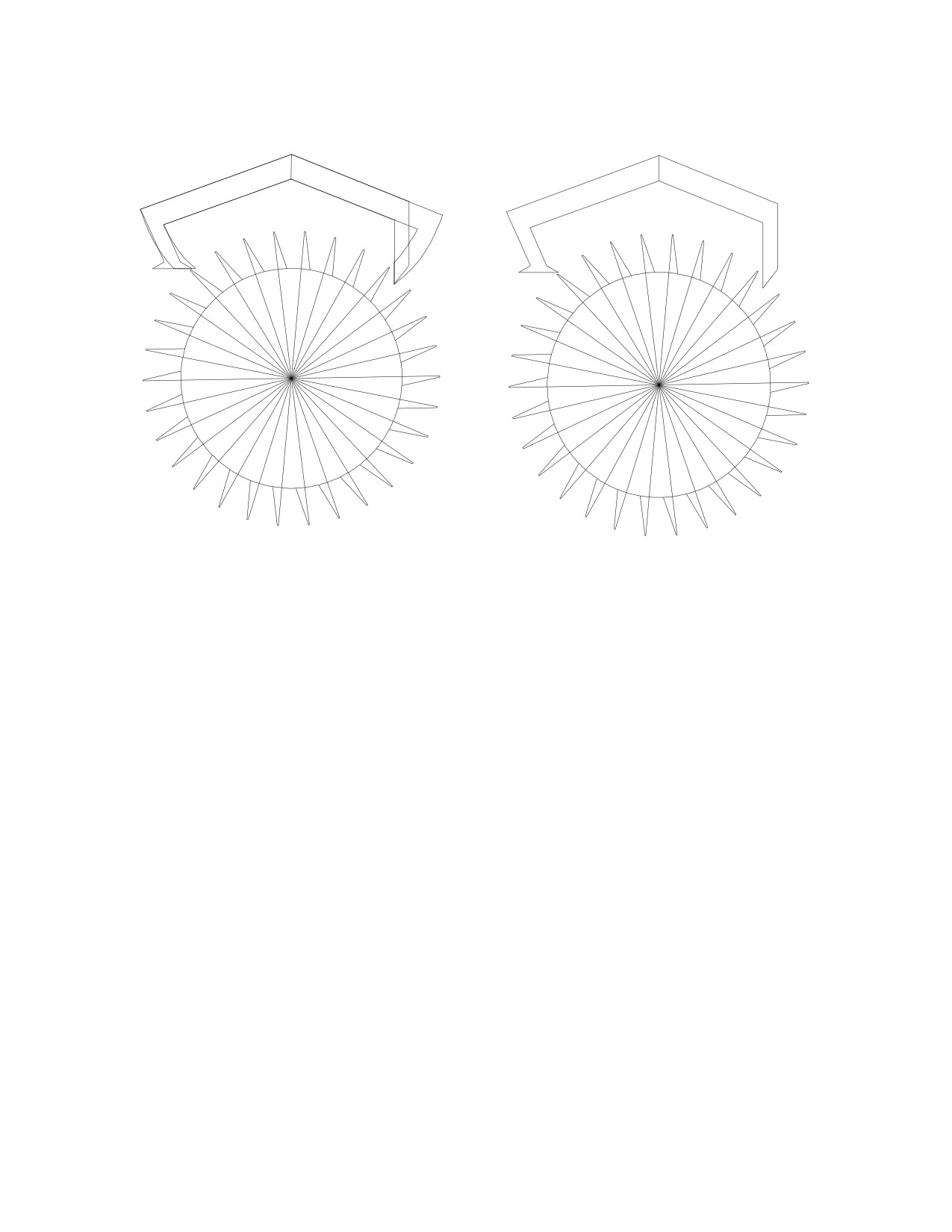
This design is similar to one I saw recently in an antique British grandfather clock:
The following is the most important fact about recoil escapements: the angle FeFi
must be 45º, regardless of the angle FeFp. This is because of recoil action. If the effi-
ciency were 50%, or 1/2, moving forwards, then the deceleration of recoil would have
twice the magnitude of Fe (in the opposite direction). Some power is "stored" in the re-
coil action because the escape wheel moves back a little, as if it were winding the clock.
However, the power stored is only 50% of Fe, so we have a very significant power loss,
even under the best conditions.
If the impulse face's angle were 15º, the efficiency would be 25%, or 1/4. The decel-
eration of recoil would be four times as large as Fe in the opposite direction. Having the
impulse face's angle at 15º causes two problems: (1) more efficiency is lost moving
forwards because of the incorrect angle, and (2) much more power is lost in recoil (going
backwards).
This example demonstrates how important the impulse face's angle is in a recoil es-
capement. The angle FeFi must be 45º to minimize power losses in recoil. Therefore, the
angle FeFp should be 90º in order to maximize efficiency moving forwards. How many
recoil escapements have you seen that had the correct angles?
17
7: The Brocot Escapement.
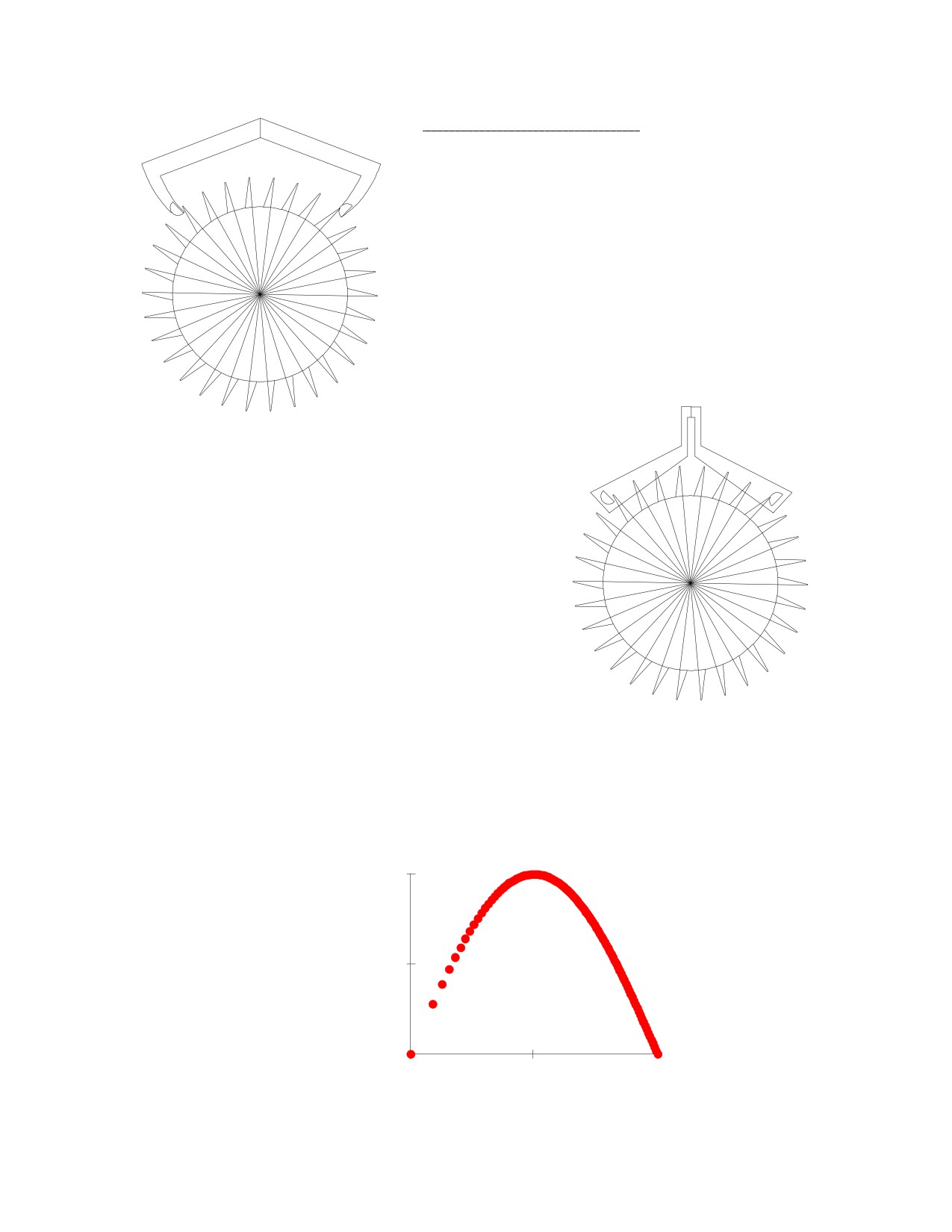
Drawing the Brocot pallets is made easier by
using a Graham drawing as background. Choose
the modified Graham, which works in the simula-
tion, because both lock and drop must be consid-
ered. Quite simply, the radius of the pallet is equal
to the thickness of the modified Graham pallet.
Then just position it over the Graham drawing so
that the lines meet.
This escape wheel drawing is borrowed from
the recoil escapement and flipped over horizon-
tally. The rest of the Brocot pallet could be drawn
as you wish:
The Brocot pallets require both lock and drop. Correctly adjusted, they could behave
much like a Graham escapement. Since the pallet is essentially half a circle, the impulse
surface is a quarter of a circle. The impulse angle changes as the tooth slides across the
impulse face. The impulse angle is therefore very inefficient at first, becoming more effi-
cient until reaching a peak, and then losing efficiency towards the end of the stroke.
Compare the Graham, which has a straight and horizontal line for Fp, with this.
0.500
F
0.250
p
0.000
0.000
45.000
90.000
angle (in degrees)
18
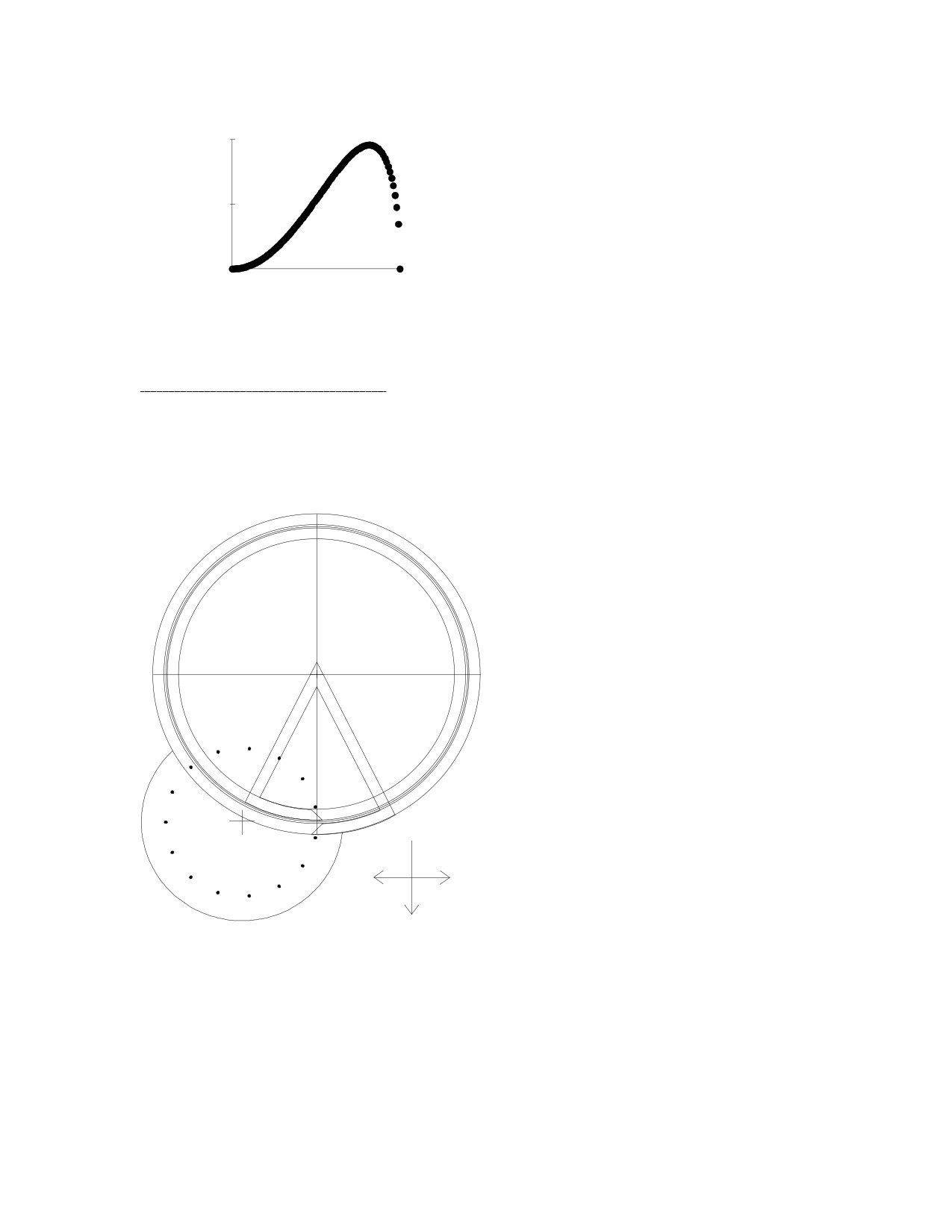
The impulse face's angle changes un-
0.008
evenly over the time it takes the escape tooth
w
to pass over the impulse face. If you consider
o
the displacement (or distance moved) of the
r
0.004
pallet in the direction of Fp, and multiply this
k
by the force Fp that rotates the pallet at each
instant in time, you get a 'work done' curve.
0.000
This curve looks very different and reveals
0.000
1.000
how inefficient the Brocot design really is.
time (index)
8: The Pin Wheel Escapement.
Drawing the pin wheel escapement proved to be a considerable challenge. A simu-
lation of the action of the pin wheel escapement is interesting when compared with that
of the Graham escapement: the action is different because of the directions of the forces
Fe and Fp, but the results are the same.
You will have noticed that, in
the Graham escapement, the angle
Fe1Fe2 was 90º, and so was the angle
Fp1Fp2. In the pin wheel escapement,
the angle Fe1Fe2 is zero (both go in
the same direction), and the angle
Fp1Fp2 is 180º. However, the angle
Fe1Fp1 is 90º, and so is the angle
Fe2Fp2. Another consideration in this
drawing is that the thickness of each
pallet is equal to half the arc between
two escape wheel teeth, as in the Gra-
ham escapement, minus enough pallet
thickness to allow for drop. The angle
of the pallet's impulse face needs to be
45º relative to Fe. The pallet locking
Fp1
Fp2
face should be designed about circles,
as in the Graham, in order to preserve
the dead-beat nature of the action.
Fe1 Fe2
19
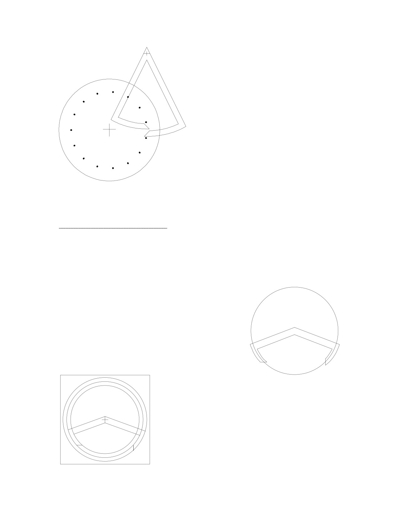
Changing the pallet circle's diameter does
not affect the number of teeth between the
pallets, as it does in the Graham. However, it
does affect the angle of swing of the pallets
(from side to side). If the pallet circle radius
were increased, the angle of swing could be
decreased, which is desirable for a fine
regulator. This would make it possible to
minimize the circular error in the movement
of the pendulum.
The lack of popularity of the pin
wheel escapement could be explained in the
difficulty in manufacturing the pallets because
of their intolerance for error: if the design
were not perfect, it probably would not work
at all, which becomes very obvious when preparing drawings for a simulation. The recoil
escapement, on the other hand, could be imprecisely designed, and it would be much
more likely to work.
9: Other Design Considerations.
In previous chapters, all the pallet designs were created with an emphasis on sym-
metry so that the impulse received by the pendulum would be equal in each direction. All
designs, whether for clocks or watches, should be based on the same method of vector
analysis. This should be clear because of the simple method of drawing one type of
escapement over another, as shown in chapters 6 and 7. Draw the impulse face first, and
then the rest of the pallet.
In watch theory, the symmetrical design is referred
to as either a "circular" design or an "equidistant im-
pulse" design. In the circular design, the impulse faces
Graham escapement
are bisected by the same circle. However, the entry
circular design
pallet's locking face is outside the circle, and the exit
pallet's locking face is inside the circle. The locking
faces clearly are not symmetrical. This problem is
unimportant in pendulum clocks, but it is an issue in
watches.
If the pallets were modified to make them with
Graham escapement
equidistant lock, the locking faces would be drawn on
equidistant lock design
the same circle. However, the pendulum would receive
unequal impulses in each direction.
20
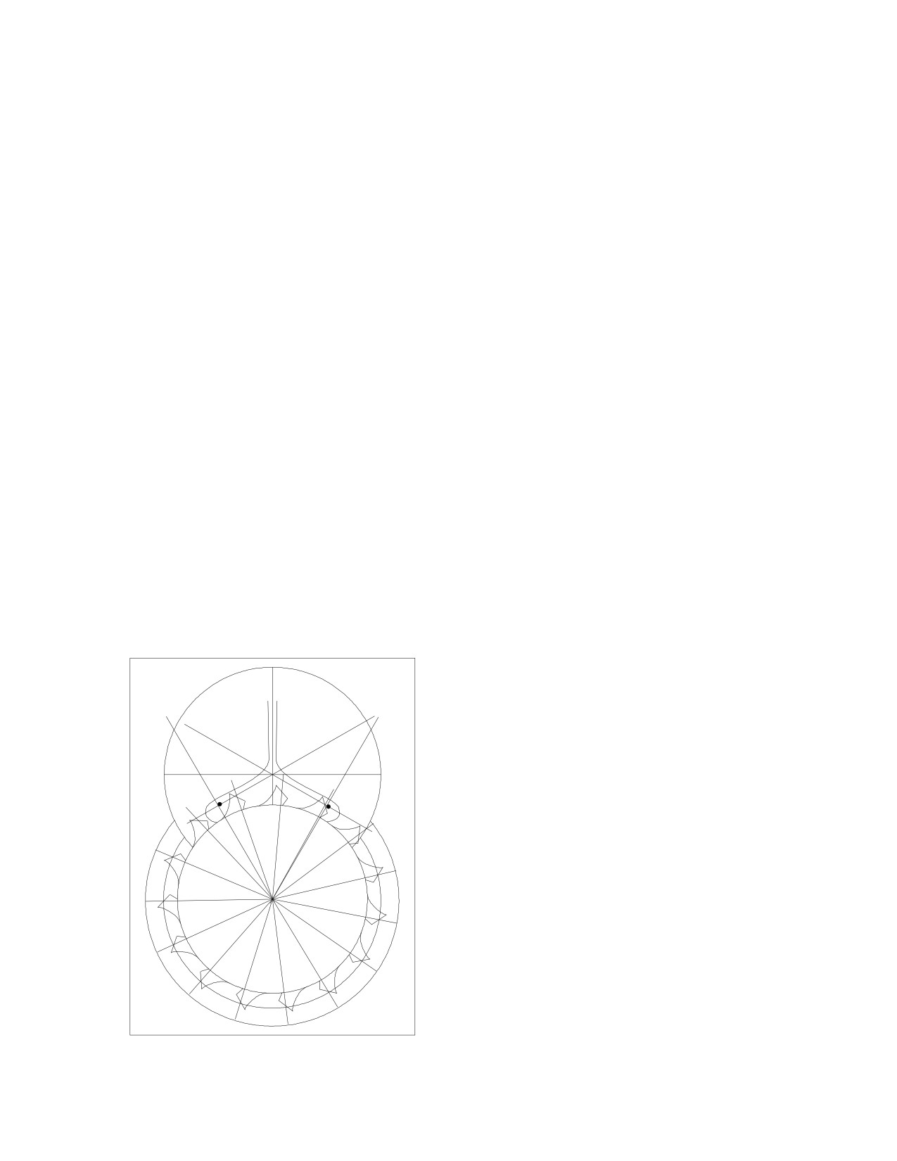
A pallet with equidistant drop could similarly be designed, but it has no practical
application in horology.
The Graham pallet has curved locking faces in order to achieve what we call a
"dead-beat," where the escape wheel does not move either forwards or backwards during
lock. When the escape wheel is pushed backwards, there is recoil. In clocks, a dead-beat
action is preferred because the movement of the pallets is controlled by the pendulum at
the point where, for example, the crutch pin goes into the suspension leader. At no time
are the pallets independent of the pendulum.
Modern Swiss watches have pallets that are independent of the balance wheel's
movement most of the time: this system is referred to as the "detached lever." The single
and double-rollers are designed so that the pallet fork would not accidentally jump across
to the wrong side of the roller jewel if the watch were jolted by a fall, for example. In
addition to the roller table, it is necessary to keep the pallet fork over to the side, in its
place, until the roller jewel returns. If the escape wheel were allowed to move forwards
slightly, beyond the entrance corner, as the pallet moves over, then it would be necessary
to move the escape wheel backwards by the same amount when the roller jewel returns to
unlock the pallet. The need to push the escape wheel backwards slightly results in a small
binding action, which encourages the pallet to stay in its place. Watch pallets, therefore,
instead of having curved locking faces, have flat locking faces at an angle of about 15º
from the escape circle radius at the pallet entrance corner, such as to make the escape
wheel rotate by about 1º extra. Watchmakers call this "Draw."
An equidistant lock design is important in watches because of the need for
symmetrical lock. In a circular design, the locking faces are at unequal distances from the
pallet center, causing a need for unequal torque to unlock, torque that adversely affects
the oscillation of the balance wheel. Any asymmetry in the oscillation of the balance
wheel could add to a factor that causes positional error, such as the poise of the balance
wheel.
Since clocks do not have pallets that are
independent from the pendulum, there is no
need for draw. Therefore, the equidistant
lock design is of no advantage in pendulum
clocks. The equidistant impulse design is the
obvious choice for the Graham, Recoil, and
Brocot escapements. (It cannot be applied to
the Pin Wheel escapement, as its drawing
demonstrates.)
The same principles of lock and draw
apply to pin pallet escapements in watches
and clocks with balance wheels, but the
impulse and locking faces and the angle of
draw are designed into the escape wheel's
tooth rather than the pallet. (A pin pallet es-
capement for a pendulum clock, such as the
Brocot, requires no draw and should have a
dead-beat action.)
If you look at a clock with a floating
21
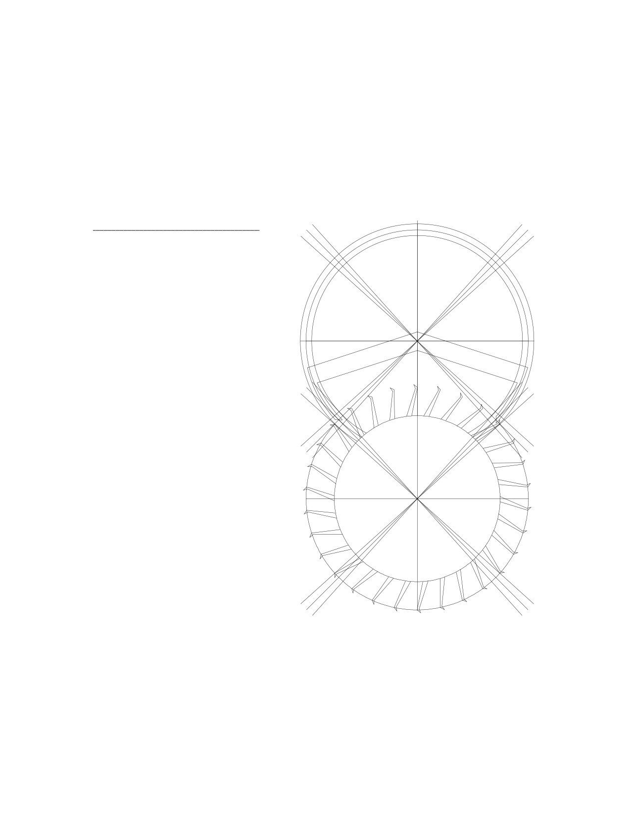
balance, such as a Hermle, you would see that the impulse face is part of the escape
tooth. In a drawing, the pallet radius lines bisect the pallet pins. The escape radius lines
bisect the impulse faces of the teeth. The locking faces of the escape teeth are not parallel
to the escape radius lines, but appear to lean forwards to create draw. The length of the
escape impulse face lines is shortened to allow for at least 1º of drop, and these lines are
at 45º to the escape circle's radius lines that bisect each of them.
By drawing the different escapements, you could see how the principles, by which
they are formed, apply to all of them. They look different, but they actually behave in
similar ways.
10: The Graham Reconsidered.
The Graham design in chapter
5 did not maximize efficiency,
whereas the drawing in chapter 3,
before modification, had the maxi-
mum achievable efficiency. The
modified Graham was less efficient
because of lock: if modified with
maximum efficiency, the escape
tooth would always land on the
pallet's entrance corner. The reason
the Graham pallets could not be
modified as efficiently as possible,
whereas an efficient watch escape-
ment could be created
(and it
would work in a simulation), is be-
cause of the design of the escape
wheel. The watch escape wheel has
an impulse face of its own and its
let-off corner is above its entrance
corner, which creates lock. The
back of the tooth makes it possible
to reduce drop without binding.
The watch escape wheel offers
these two design advantages. If the
Graham escapement were designed
with a club-tooth type escape
wheel, the pallets could easily be
modified in a more efficient design that would work in a simulation. These pallets
would be much thinner and of equidistant impulse.
There are other ways to change the design of the Graham. The 30 tooth escape
wheel is the most widely accepted choice because grandfather clocks with the
one-second pendulum could display a second hand moving by one second at a time.
If the issue of efficiency were considered, the 15 tooth escape wheel would be more
efficient by 8.33%. Since the drop requirement is the same for both the 15 and 30
tooth designs, the 15 tooth design loses 1º for drop out of every 12º, but the 30 tooth
22
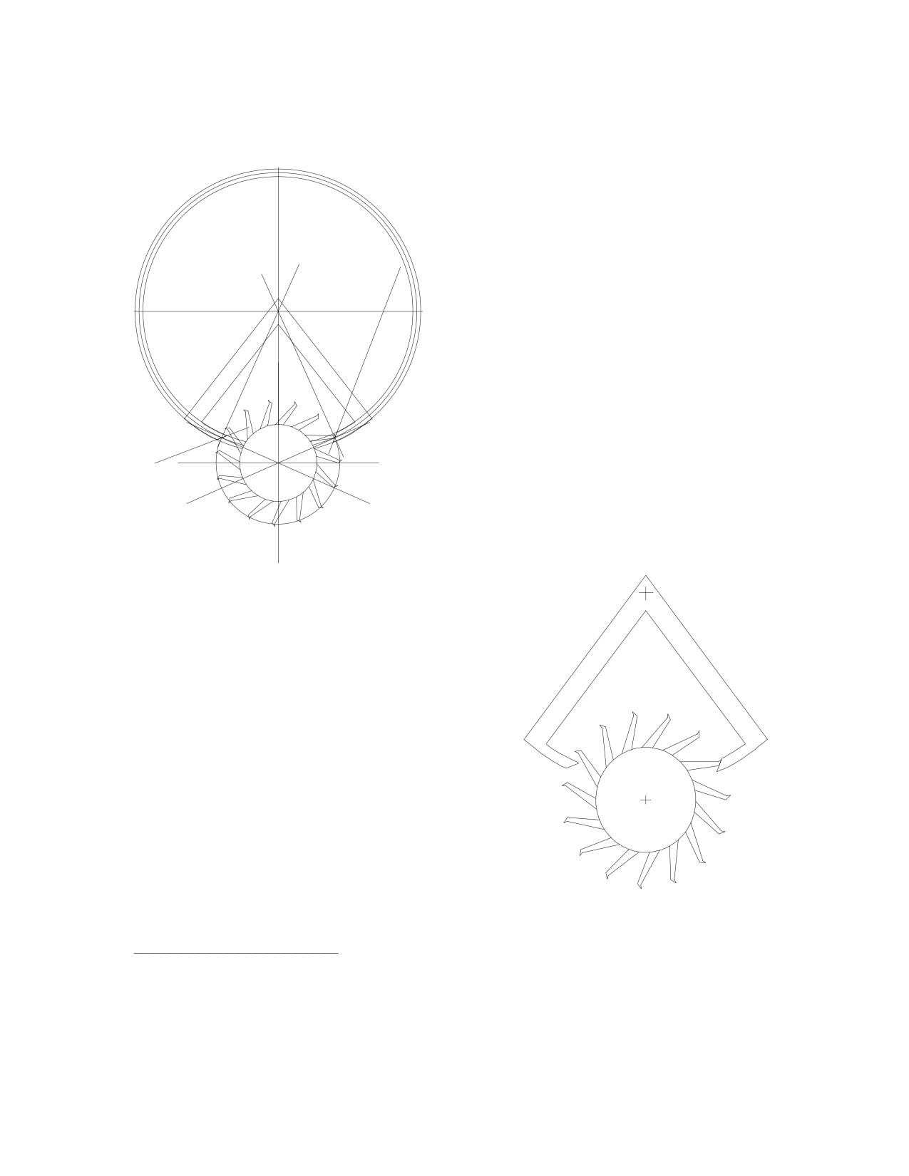
design loses 1º out of every 6º. If the Graham were designed with a 15 tooth escape
wheel, its efficiency could be improved significantly.
However, the 15 tooth escape wheel
rotates by 12º per beat, so if the pallet
circle's radius were equal to the escape
circle's radius, the pendulum would have a
greater arc of swing, which would be
undesirable. By increasing the pallet
circle's radius to approximately double the
r = 3 tan 66 = 6.74
escape circle's radius, (because the angle
of rotation per beat is doubled), the arc of
swing of the pendulum could remain
virtually unchanged. With a
5.5 tooth
span, the pallet circle's radius increases
from 3" to 6.74". Thicker, stronger pallets
and escape teeth could then be designed.
66
66
This drawing shows how the impulse
face of the escape tooth extends beyond
r=3
the circumference of the escape circle,
which passes through the tooth's entrance
corner. This is how lock could be created
and yet maximize the efficiency of the
pallet impulse face's angle.
This design has practical limitations. It
would require either a two-second pendulum or
that a different set of gear train ratios be used
to keep the one-second pendulum. An ap-
propriate gear train combination could be
found in the De Carle "Watch and Clock Ency-
clopedia." If a two-second pendulum were
used, a 60 second dial could be used, but the
second hand would move forwards every two
seconds.
Nevertheless, this example should be
useful to clockmakers interested in escapement
design because an efficiency improvement of
over 8% is well worth considering.
11: Efficiency in Numbers.
This chapter addresses the math behind the drawings: first, how changing the
directions of the forces results in reductions in magnitude; how the efficiency of an
escapement design could be calculated; and how to design a pallet blank, by using these
calculations, for a clock that is missing the pallets.
23
1.0
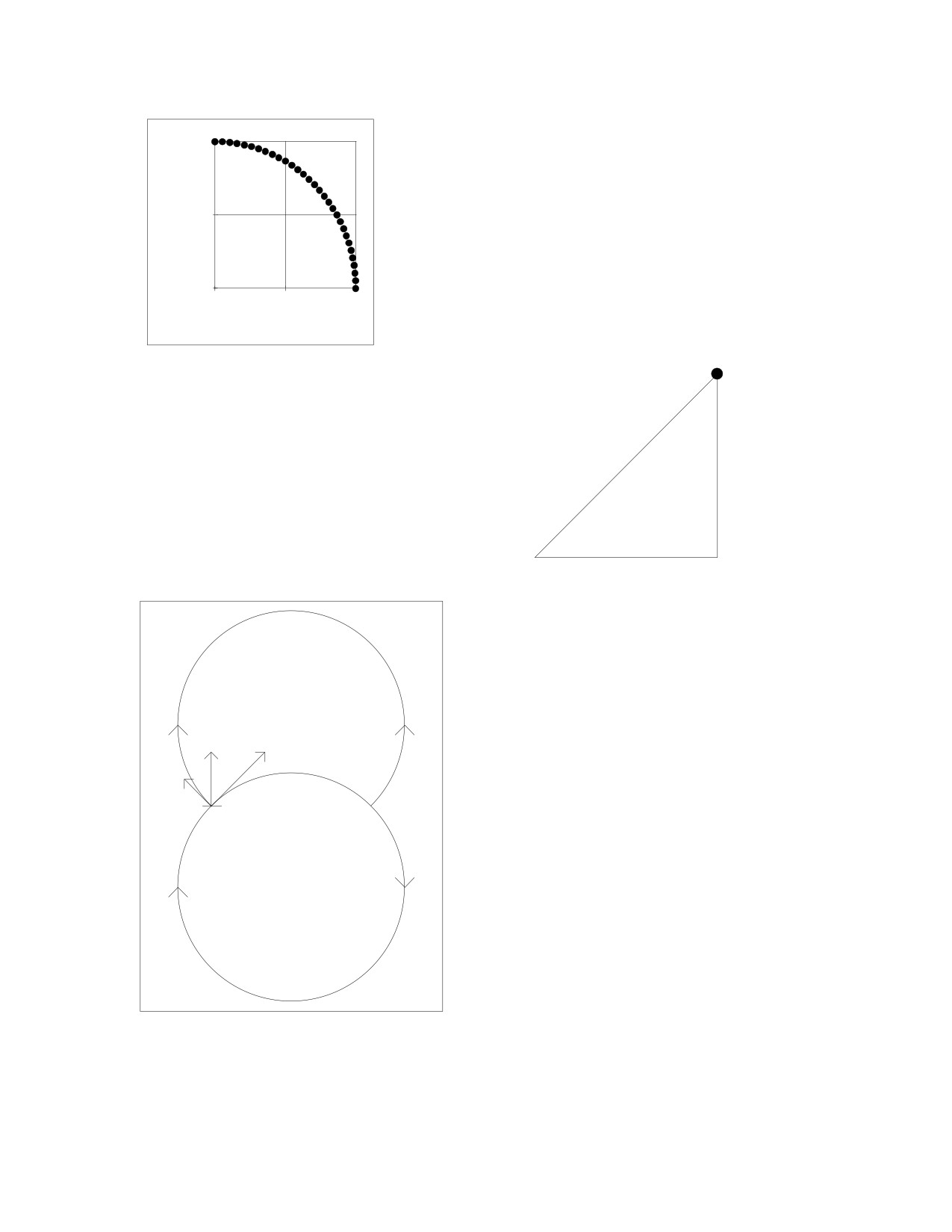
Consider the coordinates of a quarter circle. If
you take a horizontal line one inch long and rotate it
by one degree at a time until you trace a quarter of a
circle, you have points on a drawing which shows the
Y
0.5
position of each point relative to a horizontal line and
a vertical line.
0.0
0.0
0.5
1.0
X
In the above graph, the value of each
(X,Y)
point along the X line is given by:
X= cos (A)
where A is the angle of the line from the
horizontal line. The value of each point along
H = 1
the Y line is given by:
Y = H x SIN(A)
Y= sin (A)
So each point has a coordinate (X, Y), which
could be seen as (cos (A), sin (A)).
angle A
90º
(0,0)
X = H x COS(A)
PALLETS
This could be applied to clock escape-
ments. In chapter 4, we considered the action
Fi
Fe1
of the escape wheel's tooth as it pushed upon
Fp1
the entry pallet. The tooth exerted a force Fe
in a North-East direction. Since the impulse
impulse
face
face was horizontal, it received the impulse
due North.
ESCAPE
WHEEL
24
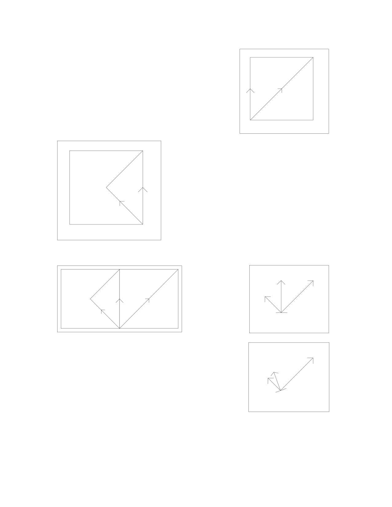
If the lines were positioned to create a triangle,
they could be used for calculation. Fe (100%) goes
North-East. Fi is the portion acting due North:
Fi
Fi = Fe x cos (45) = 100% x 0.707
Fe
= 70.7%
29.3% efficiency has just been lost!
45
As the pallet is pushed by the tooth, it rotates
clockwise, so a portion of Fi is received by the
pallet to push it in a North-West direction.
Fi
90
As before, calculate the size of Fp:
Fp = Fi x cos (45) = 70.7% x 0.707
45
= 50%
Fp
Fp is therefore half as large as Fe. The efficiency is
50%.
This...
could be used to create this:
90
Fi
Fe1
Fi
Fp1
90
Fe
45
impulse
45
45
Fp
face
Fe1
If the angle of the pallet's impulse
face were changed, the direction of Fi
Fi
would change, and therefore the pro-
Fp1
65
portion of Fe that could be used to
rotate the pallet:
impulse
face
25
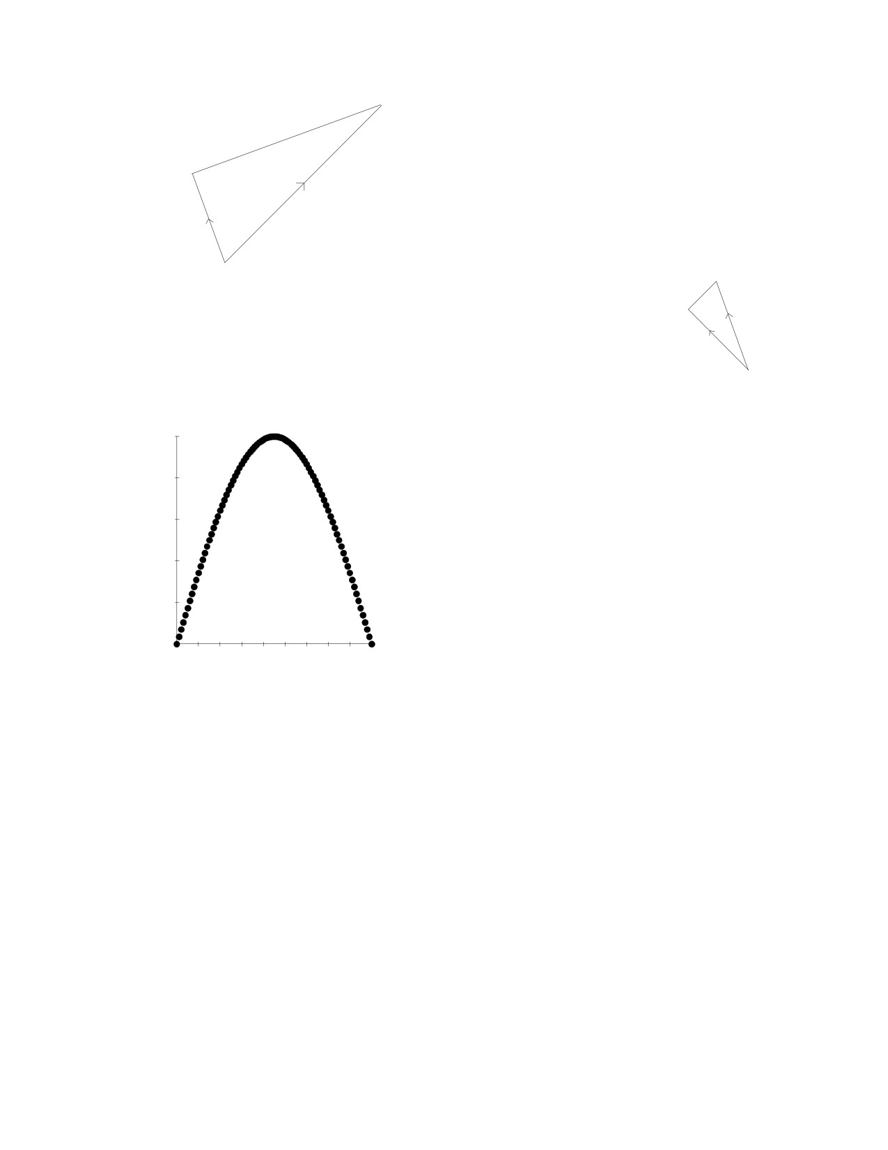
Fi = Fe x cos (65) = 100% x 0.423
90
Fe
= 42.3%
Fi
65
The angle FeFp is 90º, and the angle FeFi is 65º, so the angle FiFp is 25º.
90
Fp = Fi x cos (90-65) = 42.3% x cos (25)
Fi
25
= 42.3% x 0.906
Fp
= 38.3%
This is less efficient by almost 24% (divide 38.3 by 50) because Fi is not
half way between Fe and Fp.
When the angle between two vectors is small,
50
the loss of efficiency is small: when the angle
%
FiFp is only 25º, the efficiency drops from 42.3%
e
40
to
38.3%, a decline much smaller than occurs
f
between Fe (100%) and Fi (42.3%) when the
f
i
30
angle is larger (65º). Therefore, the angle FeFp
c
should be as small as possible. The effects of
i
20
angles could be computed on a spreadsheet. Look
e
at the chart after this page. As the angle FeFi
n
c
10
increases, the efficiency increases until Fi is half
y
way between Fe and Fp, beyond which the effi-
0
ciency decreases. The graph was created using the
0
10 20 30 40 50 60 70 80 90
data in this chart. In order for a computer to do
angle between Fe and Fi
the calculations, the angles need to be expressed
in radians: multiply the angles by pi
(3.1415) and divide by 180.
The same chart could be used to see what happens when the angle FeFp is changed.
The second chart on the following page shows that as the angle FeFp increases, the maxi-
mum achievable efficiency decreases. The maximum efficiency consistently occurs when
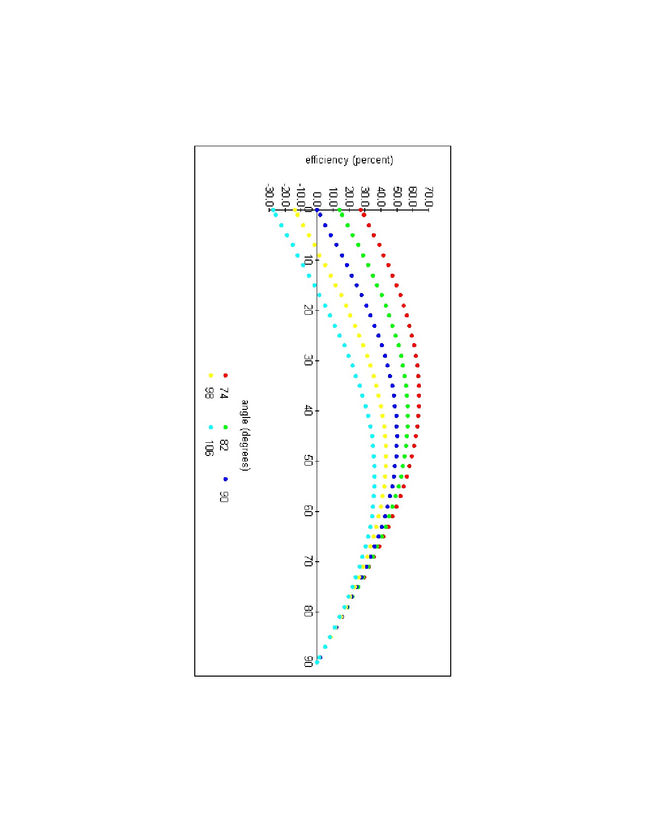
Fi is half way between Fe and Fp. This chart was used to create the graph on the page
after it. The graph illustrates how the maximum efficiency changes.
Use this chart to determine the effect of having an angle greater than 90º between Fe
and Fp on the entry side. Then determine the effect of having an angle smaller than 90º
to the same extent on the exit side. (See page 10.) You would see that the gain in
efficiency on the exit side is offset by the loss of efficiency on the entry side, so the
overall efficiency remains the same. Since there is no advantage in this asymmetry, an
angle of 90º on both the entry and the exit sides is preferred.
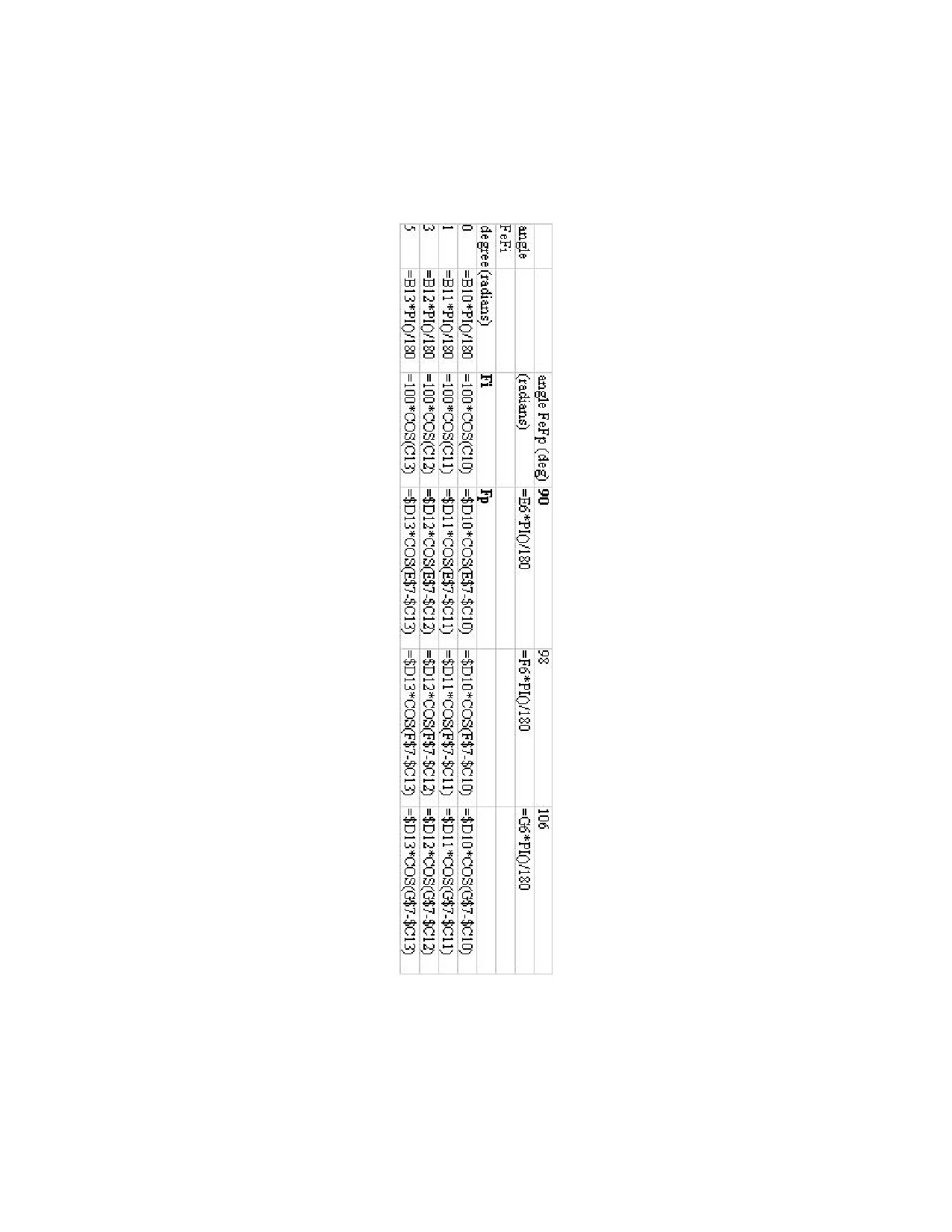
Anyone with a computer spreadsheet could create this chart. I am using MS Works.
The chart on the page following the graph shows the formulas used. Enter one of the Fp
formulas in the appropriate cell, and then use the "fill-right" and "fill-down" functions to
complete the chart. You could create a chart showing the angles increasing by 1º at a
time. (I chose 2º so as to fit the chart on one page.)
26
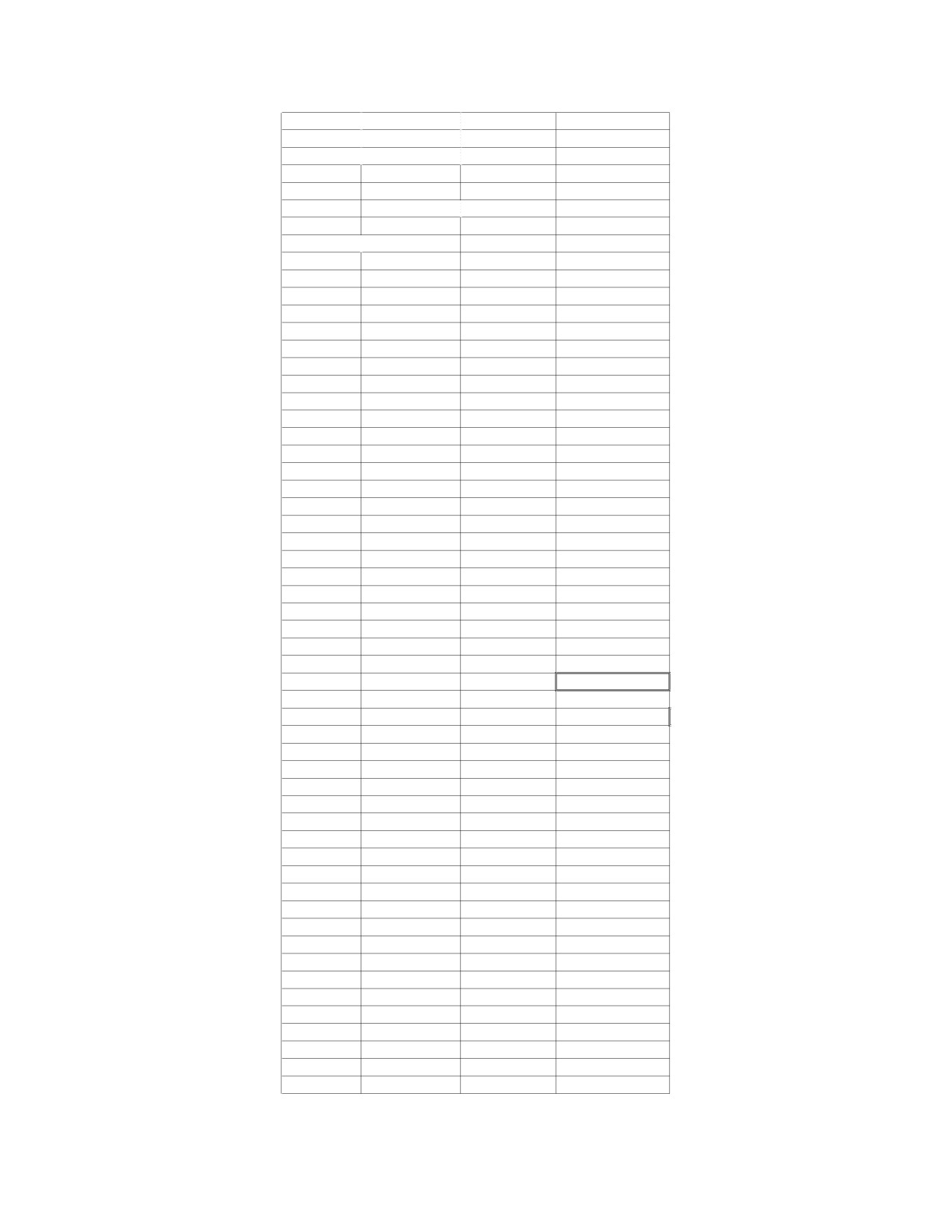
Fe = vector force by escape wheel = 100%
Fi = vector force received by pallet impulse face
Fp = vector force acting to rotate pallet
angle between Fe and Fp in degrees
90
(radians)
1.571
angle between Fe and Fi
degrees
(radians)
Fi
Fp
0
0.000
100.0
0.0
1
0.017
100.0
1.7
3
0.052
99.9
5.2
5
0.087
99.6
8.7
7
0.122
99.3
12.1
9
0.157
98.8
15.5
11
0.192
98.2
18.7
13
0.227
97.4
21.9
15
0.262
96.6
25.0
17
0.297
95.6
28.0
19
0.332
94.6
30.8
21
0.367
93.4
33.5
23
0.401
92.1
36.0
25
0.436
90.6
38.3
27
0.471
89.1
40.5
29
0.506
87.5
42.4
31
0.541
85.7
44.1
33
0.576
83.9
45.7
35
0.611
81.9
47.0
37
0.646
79.9
48.1
39
0.681
77.7
48.9
41
0.716
75.5
49.5
43
0.750
73.1
49.9
45
0.785
70.7
50.0
47
0.820
68.2
49.9
49
0.855
65.6
49.5
51
0.890
62.9
48.9
53
0.925
60.2
48.1
55
0.960
57.4
47.0
57
0.995
54.5
45.7
59
1.030
51.5
44.1
61
1.065
48.5
42.4
63
1.100
45.4
40.5
65
1.134
42.3
38.3
67
1.169
39.1
36.0
69
1.204
35.8
33.5
71
1.239
32.6
30.8
73
1.274
29.2
28.0
75
1.309
25.9
25.0
77
1.344
22.5
21.9
79
1.379
19.1
18.7
81
1.414
15.6
15.5
83
1.449
12.2
12.1
85
1.484
8.7
8.7
87
1.518
5.2
5.2
89
1.553
1.7
1.7
90
1.571
0.0
0.0
27
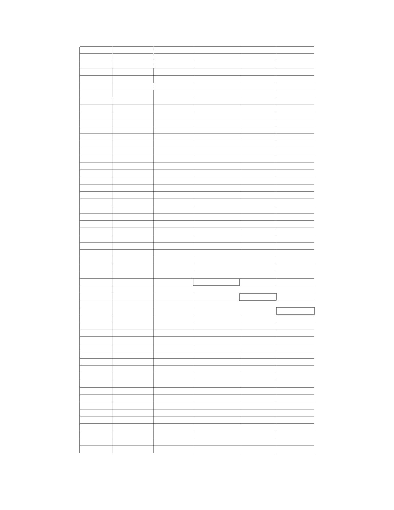
Fe = vector force by escape wheel = 100%
Fi = vector force received by pallet impulse face
Fp = vector force acting to rotate pallet
angle between Fe and Fp in degrees
90
98
106
(radians)
1.571
1.710
1.850
angle between Fe and Fi
degrees
(radians)
Fi
Fp
0
0.000
100.0
0.0
-13.9
-27.6
1
0.017
100.0
1.7
-12.2
-25.9
3
0.052
99.9
5.2
-8.7
-22.5
5
0.087
99.6
8.7
-5.2
-19.0
7
0.122
99.3
12.1
-1.7
-15.5
9
0.157
98.8
15.5
1.7
-12.0
11
0.192
98.2
18.7
5.1
-8.6
13
0.227
97.4
21.9
8.5
-5.1
15
0.262
96.6
25.0
11.8
-1.7
17
0.297
95.6
28.0
15.0
1.7
19
0.332
94.6
30.8
18.0
4.9
21
0.367
93.4
33.5
21.0
8.1
23
0.401
92.1
36.0
23.8
11.2
25
0.436
90.6
38.3
26.5
14.2
27
0.471
89.1
40.5
29.0
17.0
29
0.506
87.5
42.4
31.3
19.7
31
0.541
85.7
44.1
33.5
22.2
33
0.576
83.9
45.7
35.4
24.5
35
0.611
81.9
47.0
37.2
26.7
37
0.646
79.9
48.1
38.7
28.6
39
0.681
77.7
48.9
40.0
30.4
41
0.716
75.5
49.5
41.1
31.9
43
0.750
73.1
49.9
41.9
33.2
45
0.785
70.7
50.0
42.6
34.3
47
0.820
68.2
49.9
42.9
35.1
49
0.855
65.6
49.5
43.0
35.7
51
0.890
62.9
48.9
42.9
36.1
53
0.925
60.2
48.1
42.6
36.2
55
0.960
57.4
47.0
41.9
36.1
57
0.995
54.5
45.7
41.1
35.7
59
1.030
51.5
44.1
40.0
35.1
61
1.065
48.5
42.4
38.7
34.3
63
1.100
45.4
40.5
37.2
33.2
65
1.134
42.3
38.3
35.4
31.9
67
1.169
39.1
36.0
33.5
30.4
69
1.204
35.8
33.5
31.3
28.6
71
1.239
32.6
30.8
29.0
26.7
73
1.274
29.2
28.0
26.5
24.5
75
1.309
25.9
25.0
23.8
22.2
77
1.344
22.5
21.9
21.0
19.7
79
1.379
19.1
18.7
18.0
17.0
81
1.414
15.6
15.5
15.0
14.2
83
1.449
12.2
12.1
11.8
11.2
85
1.484
8.7
8.7
8.5
8.1
87
1.518
5.2
5.2
5.1
4.9
89
1.553
1.7
1.7
1.7
1.7
90
1.571
0.0
0.0
0.0
0.0
28
29
30

These figures consider the action of the ideal Graham
6
escapement. In this case, the 30 tooth escape wheel rotates
by 6º and the pallet rotates by 6º as the escape tooth pushes
on the pallet's impulse face.
6
In practice, if
1º were lost for drop, the triangle
5
would become smaller.
5
To calculate the work done, multiply the force, which was calculated to be 50% (or
0.5), by the distance (in the direction of Fp) that the pallet is pushed during impulse.
Take the distance as an index of 1 (or 100%), so the work done is: 1 x 0.5 = 0.5. Divide
the distance into six parts because there are 6º of rotation and you need to compare it
with the distance in the practical pallet, after losing 1º to drop. In the practical example,
the distance is: 1 x 5/6 = 0.833. The work done is: 0.5 x 0.833 = 0.417. Therefore, over
16% efficiency is lost to drop.
Compare the Graham's efficiency with that of the Brocot. This is more complicated
because the angle of the impulse face changes as the tooth slides across the pallet surface.
Since the Brocot impulse surface is a quarter of a circle, the cosine function could be
used to find the angles of the impulse face over the time it takes the tooth to slide from
one end of the pallet to the other. Then Fi and Fp could be calculated for each angle,
followed by the distance the pallet travels in the direction of Fp (in each instant of time).
The force Fp and the distance (X) could be multiplied to get the work done in each
instant, which, all added together, would give the total work done to rotate the pallet in
the direction of Fp. See the Brocot chart on the next page. The total at the bottom gives
the total work done as an index, which could be compared with the ideal Graham es-
capement. Since the Brocot has a work done index of 0.384 and the Graham of 0.5, the
Brocot is less efficient by over 23%!
To get a work done index for the Brocot, allow 1º of drop, as for the Graham. Just
multiply the index by the same factor:
0.384 x 5/6 = 0.32. Therefore, you could say that
the Brocot is only 32% efficient in practice (at best).
The Brocot chart could be used to create a graph. The Brocot graph, on the
following page, shows the work done to rotate the pallet in each instant (over the time it
takes the tooth to slide across the pallet).
31

BROCOT
Fe=1
time
angle (rad)
fv
t
a
X
y
D
dD
fv*dD
0.000
1.571
0.000
0.000
0.000
0.000
0.000
0.020
1.551
0.020
0.020
0.000
0.000
0.000
0.040
1.531
0.040
0.040
0.002
0.001
0.000
0.060
1.511
0.060
0.060
0.004
0.002
0.000
0.080
1.491
0.080
0.080
0.006
0.003
0.000
0.100
1.471
0.100
0.099
0.010
0.004
0.000
0.120
1.451
0.120
0.119
0.014
0.004
0.001
0.140
1.430
0.140
0.139
0.020
0.005
0.001
0.160
1.410
0.160
0.158
0.026
0.006
0.001
0.180
1.390
0.180
0.177
0.032
0.007
0.001
0.200
1.369
0.200
0.196
0.040
0.008
0.001
0.220
1.349
0.220
0.215
0.048
0.008
0.002
0.240
1.328
0.240
0.233
0.058
0.009
0.002
0.260
1.308
0.260
0.251
0.068
0.010
0.003
0.280
1.287
0.280
0.269
0.078
0.011
0.003
0.300
1.266
0.300
0.286
0.090
0.012
0.003
0.320
1.245
0.320
0.303
0.102
0.012
0.004
0.340
1.224
0.340
0.320
0.116
0.013
0.004
0.360
1.203
0.360
0.336
0.130
0.014
0.005
0.380
1.181
0.380
0.351
0.144
0.015
0.005
0.400
1.159
0.400
0.367
0.160
0.016
0.006
0.420
1.137
0.420
0.381
0.176
0.016
0.006
0.440
1.115
0.440
0.395
0.194
0.017
0.007
0.460
1.093
0.460
0.408
0.212
0.018
0.007
0.480
1.070
0.480
0.421
0.230
0.019
0.008
0.500
1.047
0.500
0.433
0.250
0.020
0.008
0.520
1.024
0.520
0.444
0.270
0.020
0.009
0.540
1.000
0.540
0.454
0.292
0.021
0.010
0.560
0.976
0.560
0.464
0.314
0.022
0.010
0.580
0.952
0.580
0.472
0.336
0.023
0.011
0.600
0.927
0.600
0.480
0.360
0.024
0.011
0.620
0.902
0.620
0.486
0.384
0.024
0.012
0.640
0.876
0.640
0.492
0.410
0.025
0.012
0.660
0.850
0.660
0.496
0.436
0.026
0.013
0.680
0.823
0.680
0.499
0.462
0.027
0.013
0.700
0.795
0.700
0.500
0.490
0.028
0.014
0.720
0.767
0.720
0.500
0.518
0.028
0.014
0.740
0.738
0.740
0.498
0.548
0.029
0.015
0.760
0.707
0.760
0.494
0.578
0.030
0.015
0.780
0.676
0.780
0.488
0.608
0.031
0.015
0.800
0.644
0.800
0.480
0.640
0.032
0.015
0.820
0.609
0.820
0.469
0.672
0.032
0.015
0.840
0.574
0.840
0.456
0.706
0.033
0.015
0.860
0.536
0.860
0.439
0.740
0.034
0.015
0.880
0.495
0.880
0.418
0.774
0.035
0.015
0.900
0.451
0.900
0.392
0.810
0.036
0.014
0.920
0.403
0.920
0.361
0.846
0.036
0.013
0.940
0.348
0.940
0.321
0.884
0.037
0.012
0.960
0.284
0.960
0.269
0.922
0.038
0.010
0.980
0.200
0.980
0.195
0.960
0.039
0.008
1.000
0.000
1.000
0.000
1.000
0.040
0.000
0.384
32
///////////////////////////////////////