Boeing 737 - 600/700/800/900. Operations Manual (1997 year) - page 38
Engines, APU -
APU System Description
Boeing 737 Operations Manual
Intentionally
Blank
7.30.4
Boeing 737 Operations Manual
Fire Protection
Chapter 8
Table of Contents
Section 0
8.0 Fire Protection-Table of Contents
Controls and Indicators
8.10.1
Overheat/Fire Protection Panel Switches
8.10.1
Overheat/Fire Protection Panel Lights
8.10.3
Cargo Fire Panel
8.10.4
Master Fire Warning Light
8.10.6
APU Ground Control Panel
8.10.7
Lavatory Fire
8.10.8
System Description
8.20.1
Introduction
8.20.1
Engine Fire Protection
8.20.1
Engine Overheat and Fire Detection
8.20.1
Engine Fire Extinguishing
8.20.2
Engine Fire Extinguisher Schematic
8.20.3
APU Fire Protection
8.20.4
APU Fire Detection
8.20.4
APU Fire Extinguishing
8.20.4
Main Wheel Well Fire Protection
8.20.5
Main Wheel Well Fire Detection
8.20.5
Cargo Compartment Fire Protection
8.20.5
Cargo Compartment Smoke Detection
8.20.5
Cargo Compartment Fire Warning
8.20.5
Cargo Compartment Fire Extinguishing
8.20.6
Cargo Fire Extinguisher Schematic
8.20.6
Lavatory Fire Protection
8.20.6
Lavatory Smoke Detection
8.20.6
Lavatory Fire Extinguisher System
8.20.7
Fire and Overheat System Tests
8.20.7
FAULT/INOP Test Detection
8.20.7
OVERHEAT/FIRE Test Detection
8.20.7
8.TOC.0.1
Fire Protection -
Table of Contents
Boeing 737 Operations Manual
Extinguisher Test
8.20.8
Cargo Fire System Tests
8.20.8
Cargo Fire TEST
8.20.8
Cargo Fire Extinguisher Test
8.20.8
8.TOC.0.2
Boeing 737 Operations Manual
Fire Protection
Chapter 8
Controls and Indicators
Section 10
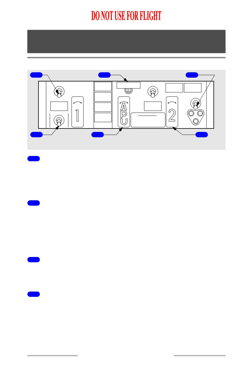
Overheat/Fire Protection Panel Switches
1
2
3
OVHT DET
OVHT DET
WHEEL
BELL CUTOUT
L BOTTLE
R BOTTLE
WELL
DISCHARGE
DISCHARGE
A
B
A
B
ENGINES
NORMAL
DISCH
FAULT
DISCH
NORMAL
DISCH
E
T
X
E
1
2
ENG 1
L
R
ENG 2
L
R
T
S
OVERHEAT
APU DET
OVERHEAT
T
INOP
R
TEST
FIRE SWITCHES
L
F
I
O
F
APU BOTTLE
A
(FUEL SHUTOFF)
U
N
V
I
DISCHARGE
PULL WHEN ILLUMINATED
L
O
H
R
P
T
E
LOCK OVERRIDE: PRESS
T
BUTTON UNDER HANDLE
APU
4
5
6
AFT ELECTRONIC PANEL
1
Overheat Detector (OVHT DET) Switch
NORMAL - detection loop A and loop B are active.
A - detection loop A is active.
B - detection loop B is active.
2
Fire Warning BELL CUTOUT Switch
Push -
• extinguishes both master FIRE WARN lights
• silences the fire warning bell
• silences the remote APU fire warning horn (on the ground only)
• resets the system for additional warnings.
3
Extinguisher (EXT) TEST Switch
(spring-loaded to center)
1 or 2 - tests bottle discharge circuits for all three extinguisher bottles.
4
Fault/Inoperative (FAULT/INOP) and
Overheat/Fire (OVHT/FIRE) TEST Switch
(spring-loaded to center)
FAULT/INOP - tests fault detection circuits for both engines and the APU.
8.10.1
Fire Protection -
Controls and Indicators
Boeing 737 Operations Manual
OVHT/FIRE - tests overheat and fire detection loops on both engines and APU,
and wheel well fire detector
Note: See Fire and Overheat Detection System Fault Test in Section 20.
5
APU Fire Warning Switch
Illuminated (red) -
• indicates fire in APU
• unlocks APU fire warning switch.
Note: Master FIRE WARN lights illuminate, fire warning bell sounds, and in the
main wheel well the APU fire warning horn sounds (on ground only), and
APU fire warning light flashes.
In - normal position, mechanically locked if no fire signal.
Up -
• arms APU extinguisher circuit
• closes fuel shutoff valve, APU bleed air valve, and APU inlet door
• trips generator control relay and breaker
• allows APU fire warning switch to rotate.
Rotate (left or right) -
• discharges APU fire bottle.
6
Engine Fire Warning Switch
Illuminated (red) -
• indicates fire in related engine
• unlocks related engine fire warning switch.
Note: Master FIRE WARN lights illuminate and fire warning bell sounds.
In - normal position, mechanically locked if no fire signal.
Up -
• arms one discharge squib on each engine fire extinguisher
• closes fuel, hydraulic shutoff and engine bleed air valves
• disables thrust reverser
• trips generator control relay and breaker
• deactivates engine driven hydraulic pump LOW PRESSURE light
• allows engine fire warning switch to rotate.
Rotate (left or right) - discharges related fire bottle.
8.10.2
Fire Protection -
Controls and Indicators
Boeing 737 Operations Manual
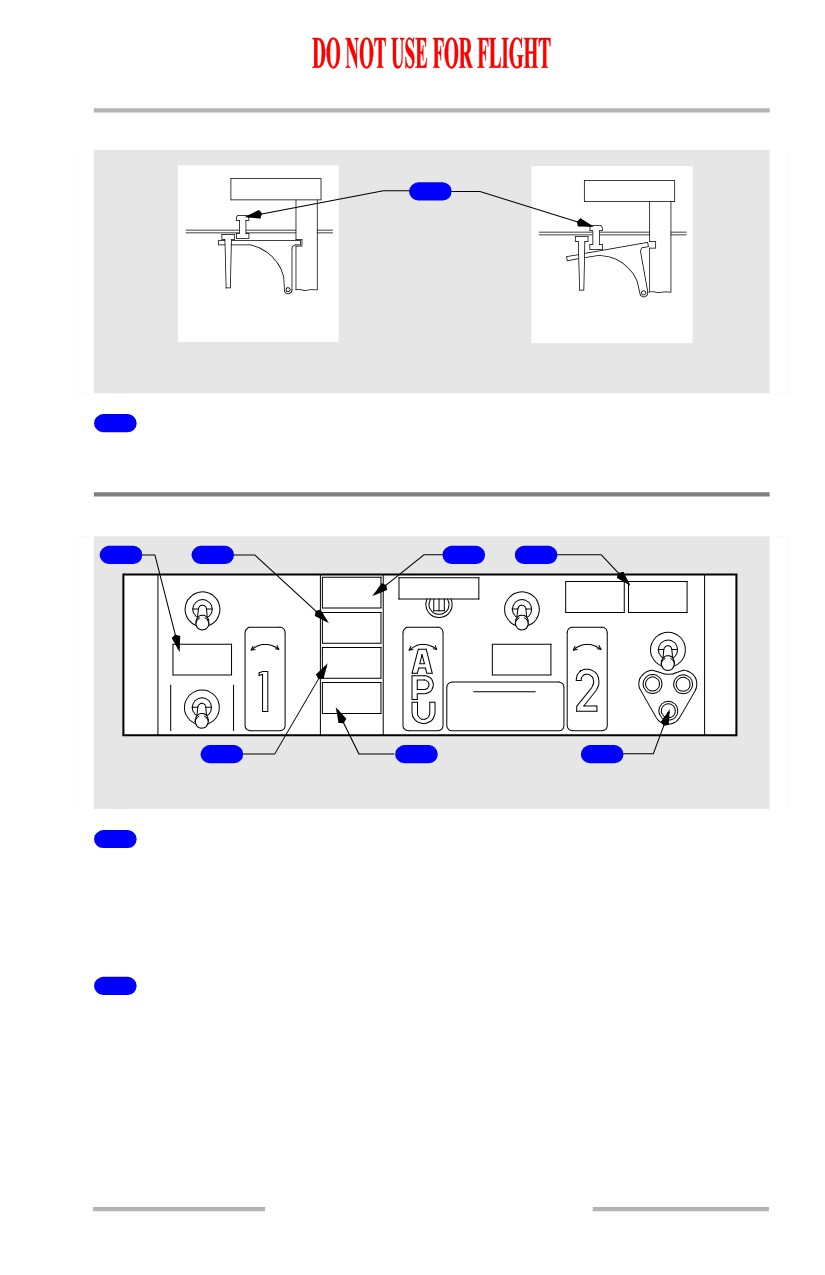
Fire Warning Switch Override
FIRE SWITCH
1
FIRE SWITCH
LOCKED (NORMAL)
UNLOCKED
AFT ELECTRONIC PANEL
1
Fire Warning Switch Override
Push - unlocks fire warning switch.
Overheat/Fire Protection Panel Lights
1
2
3
4
OVHT DET
WHEEL
BELL CUTOUT
OVHT DET
L BOTTLE
R BOTTLE
WELL
DISCHARGE
DISCHARGE
A
B
A
B
FAULT
ENGINES
NORMAL
DISCH
DISCH
NORMAL
DISCH
E
T
X
E
1
2
ENG 1
L
R
APU DET
ENG 2
L
R
T
S
OVERHEAT
OVERHEAT
T
INOP
R
TEST
L
F
I
O
F
APU BOTTLE
FIRE SWITCHES
A
N
V
I
DISCHARGE
(FUEL SHUTOFF)
U
O
H
R
PULL WHEN ILLUMINATED
L
P
T
E
LOCK OVERRIDE: PRESS
T
BUTTON UNDER HANDLE
APU
5
6
7
AFT ELECTRONIC PANEL
1
Engine (ENG) OVERHEAT Light
Illuminated (amber) - indicates overheat in related engine.
Note: MASTER CAUTION and OVHT/DET system annunciator lights
illuminate.
2
FAULT Light
Illuminated (amber) - with the overheat detector switch in NORMAL - indicates
both detector loops for an engine have failed.
Illuminated (amber) - with the overheat detector switch in A or B - indicates the
selected loop for an engine has failed.
Note: MASTER CAUTION and OVHT/DET system annunciator lights do not
illuminate.
8.10.3
Fire Protection -
Controls and Indicators
Boeing 737 Operations Manual
3
WHEEL WELL Fire Warning Light
Illuminated (red) - indicates fire in main gear wheel well
Note: Master FIRE WARN lights illuminate and fire warning bell sounds.
4
Engine BOTTLE DISCHARGE Light
Illuminated (amber) - indicates related fire extinguisher bottle has discharged.
5
APU Detector Inoperative (DET INOP) Light
Illuminated (amber) - indicates APU detector loop has failed.
Note: MASTER CAUTION and OVHT/DET system annunciator lights
illuminate.
6
APU BOTTLE DISCHARGE Light
Illuminated (amber) - indicates APU extinguisher bottle has discharged.
7
Extinguisher Test (EXT TEST) Lights
Illuminated (green) - EXT TEST switch is positioned to 1 or 2
and circuit
continuity is normal.
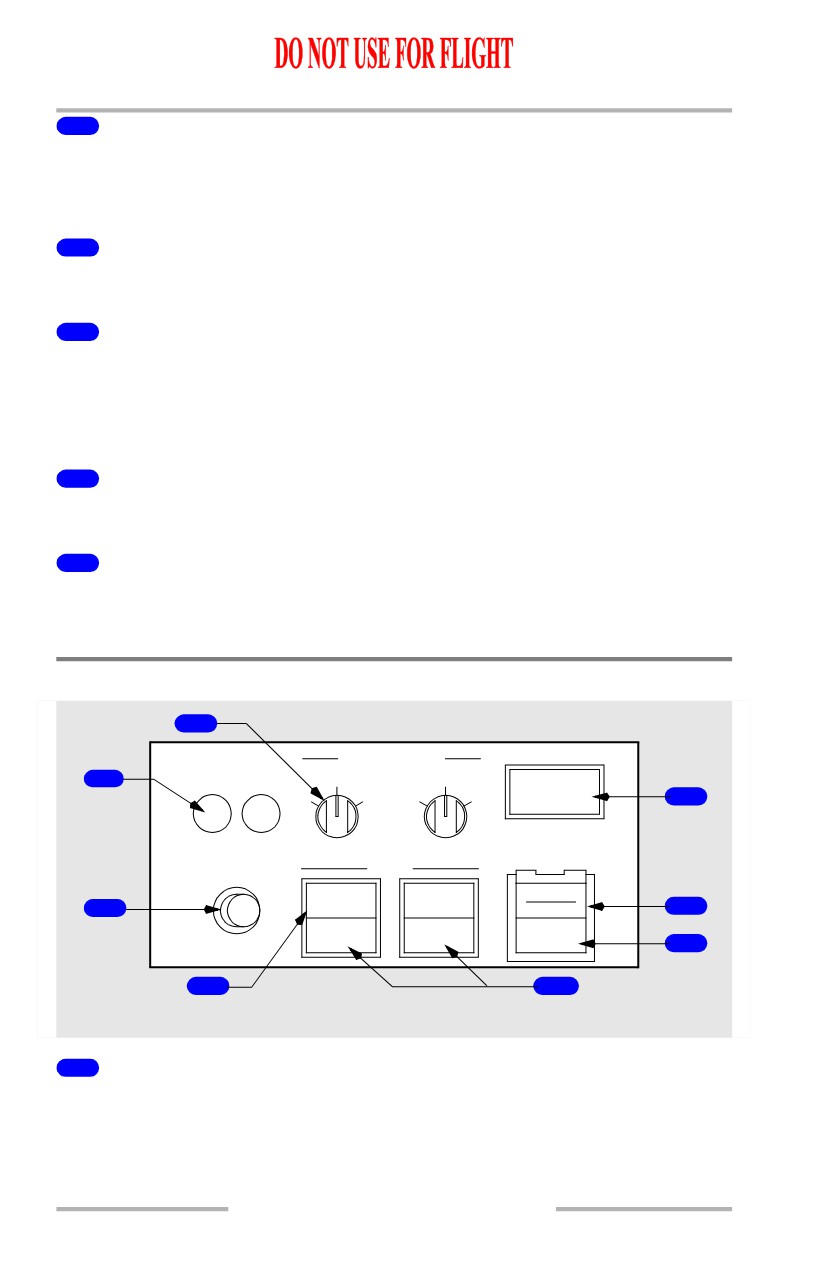
Cargo Fire Panel
2
EXT
DET SELECT
1
FWD AFT
NORM
NORM
DETECTOR
A
B
A
B
3
FAULT
C
F
A
I
R
FWD
AFT
DISCH
R
G
TEST
ARM
E
O
ARMED
ARMED
4
8
FWD
AFT
DISCH
7
5
6
AFT ELECTRONIC PANEL
1
Extinguisher (EXT) Test Lights
Illuminated (green) - Cargo Fire TEST switch is pushed and fire bottle discharge
squib circuit continuity is normal.
8.10.4
Fire Protection -
Controls and Indicators
Boeing 737 Operations Manual
2
Detector Select (DET SELECT) Switches
NORM - detection loop A and B are active.
A - detection loop A is active.
B - detection loop B is active.
3
DETECTOR FAULT Light
Illuminated (amber) -
• Both loops in one or both cargo compartments have failed
4
Cargo Fire TEST Switch
PUSH - tests circuits for both forward and aft cargo fire detector loops and
suppression system.
Note: See Cargo Fire System Tests in Section 20.
5
Cargo Fire ARM Switches
[Option - Single Cargo Fire Extinguisher bottle]
PUSH -
• FWD ARMED - extinguisher armed for the forward cargo compartment
• AFT ARMED - extinguisher armed for the aft cargo compartment.
6
Cargo Fire (FWD/AFT) Warning Lights
Illuminated (red) -
• at least one detector in each loop detects smoke
• with power failed in one loop, at least one detector on the remaining loop
detects smoke.
Note: Master FIRE WARN lights illuminate and fire warning bell sounds.
7
Cargo Fire Bottle Discharge (DISCH) Light
Illuminated (amber) - indicates the extinguisher bottle has discharged
8
Cargo Fire Discharge (DISCH) Switch
PUSH - if system is armed, discharges the extinguisher bottle.
8.10.5

Fire Protection -
Controls and Indicators
Boeing 737 Operations Manual
Master Fire Warning Light
FIRE
WARN
1
BELL CUTOUT
GLARESHIELD
1
Master Fire Warning (FIRE WARN) Lights
Illuminated (red) - indicates a fire warning (or system test) in engine, APU, main
gear wheel well or cargo compartment
• fire warning bell sounds
• if on ground, remote APU fire warning horn sounds.
Push -
• extinguishes both master FIRE WARN lights
• silences fire warning bell
• silences remote APU fire warning horn
• resets system for additional warnings.
Note: Pushing fire warning bell cutout switch on overheat/fire protection panel
results in same actions.
8.10.6
Fire Protection -
Controls and Indicators
Boeing 737 Operations Manual
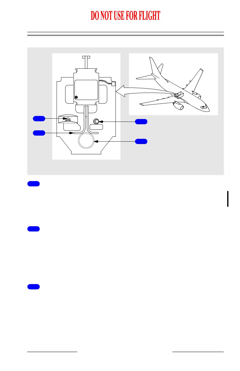
APU Ground Control Panel
A.P.U.
FIRE
CONTROL
1.PULL HANDLE DOWN
2.DISCHARGE BOTTLE
BOTTLE DISCHARGE
1
3
BOTTLE
HORN
DISCHARGE
CUTOUT
2
4
MAIN WHEEL WELL
1
APU BOTTLE DISCHARGE Switch
(spring-loaded to the right and saftied.)
Left - discharges APU extinguisher.
Note: Armed only if APU fire control handle is pulled at this panel.
2
APU Fire Control Handle
Up - normal position.
Down -
• arms APU BOTTLE DISCHARGE switch (on this panel only)
• closes APU fuel shutoff, bleed air valve and APU inlet door
• trips generator control relay and breaker.
3
APU Fire Warning HORN CUTOUT Switch
Push -
• silences fire alarm bell
• silences APU fire warning horn
• causes APU fire warning light to stop flashing but remain illuminated.
8.10.7
Fire Protection -
Controls and Indicators
Boeing 737 Operations Manual
4
APU Fire Warning Light
Illuminated (red flashing) - indicates fire in APU.
Note: Also, flight deck fire warning bell sounds and APU fire warning horn in
main wheel well sounds.
Illuminated (red steady) - indicates APU fire warning HORN CUTOUT switch
has been pushed following an APU fire indication.
Lavatory Fire
Lavatory Smoke Detection
[Option - Lavatory Smoke Light]
LAVATORY
1
SMOKE
FORWARD OVERHEAD PANEL
1
LAVATORY SMOKE Light
Illuminated (amber) -
• smoke has been detected in a lavatory
• a test is being conducted.
Note: MASTER CAUTION and OVERHEAD system annunciator lights
illuminate.
8.10.8
Fire Protection -
Controls and Indicators
Boeing 737 Operations Manual
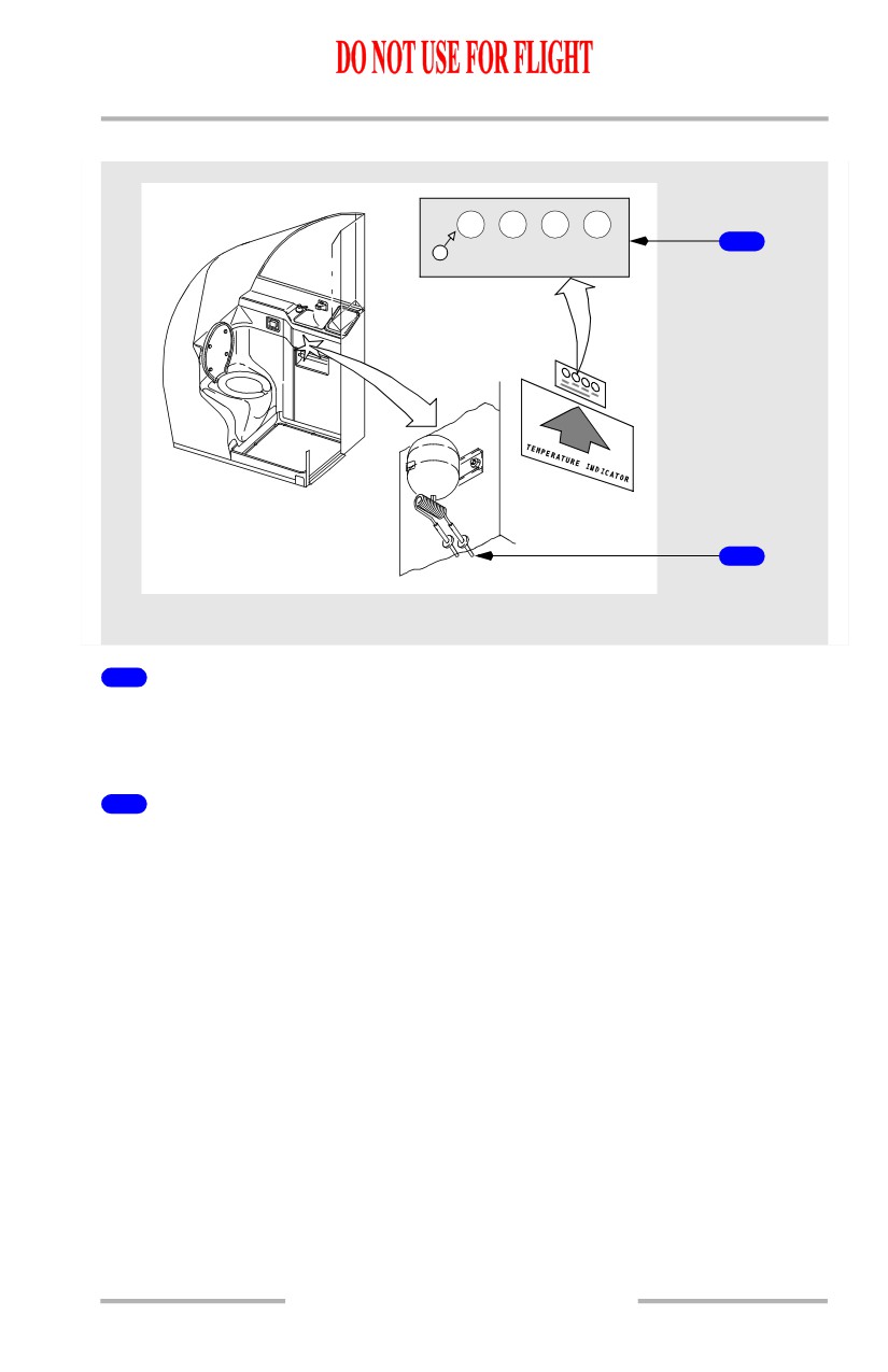
Lavatory Fire Extinguisher
180`F
200`F
230` F
250`F
1
BLACK WHEN EXPOSED
2
BELOW LAVATORY SINK
1
TEMPERATURE INDICATOR Placard
White - normal condition.
Black - exposed to high temperatures.
2
Heat Activated Nozzles
Flat black - normal condition.
Aluminum - indicates extinguisher has discharged.
8.10.9
Fire Protection -
Controls and Indicators
Boeing 737 Operations Manual
Intentionally
Blank
8.10.10
Boeing 737 Operations Manual
Fire Protection
Chapter 8
System Description
Section 20
Introduction
There are fire detection and extinguishing systems for:
• engines
• lavatories
• APU
• cargo compartments.
The engines also have overheat detection systems.
The main gear wheel well has a fire detection system, but no fire extinguishing
system.
Engine Fire Protection
Engine fire protection consists of these systems:
• engine overheat and fire detection powered by the battery bus
• engine fire extinguishing powered by the hot battery bus.
Engine Overheat and Fire Detection
Each engine contains two overheat/fire detector loops. Each loop provides both
fire and overheat detection. As the temperature of a detector increases to a
predetermined limit, the detector senses an overheat condition. At higher
temperatures, the detector senses a fire condition. Normally, both detector loops
must sense a fire or overheat condition to cause an engine overheat or fire alert.
The ENG OVERHEAT light or engine fire warning switch remains illuminated
until the temperature drops below the onset temperature.
An OVHT DET switch for each engine, labeled A, B, and NORMAL, permits
selection of either loop A or B, or both A and B, as the active detecting loops.
The system contains a fault monitoring circuit. If one loop fails with the OVHT
DET switch in NORMAL, that loop is automatically deselected and the remaining
loop functions as a single loop detector. There is no flight deck indication of single
loop failure. If both loops fail on an engine, the FAULT light illuminates and the
system is inoperative.
If the OVHT DET switch is positioned to A or B, the system operates as a single
loop system. The non-selected loop is not monitored. If the selected loop fails, the
FAULT light illuminates and the system is inoperative.
The indications of an engine overheat are:
• both MASTER CAUTION lights illuminate
• the OVHT/DET system annunciator light illuminates
• the related ENG OVERHEAT light illuminates.
8.20.1
Fire Protection -
System Description
Boeing 737 Operations Manual
The indications of an engine fire are:
• the fire warning bell sounds
• both master FIRE WARN lights illuminate
• the related engine fire warning switch illuminates
• all related engine overheat alert indications illuminate.
Engine Fire Extinguishing
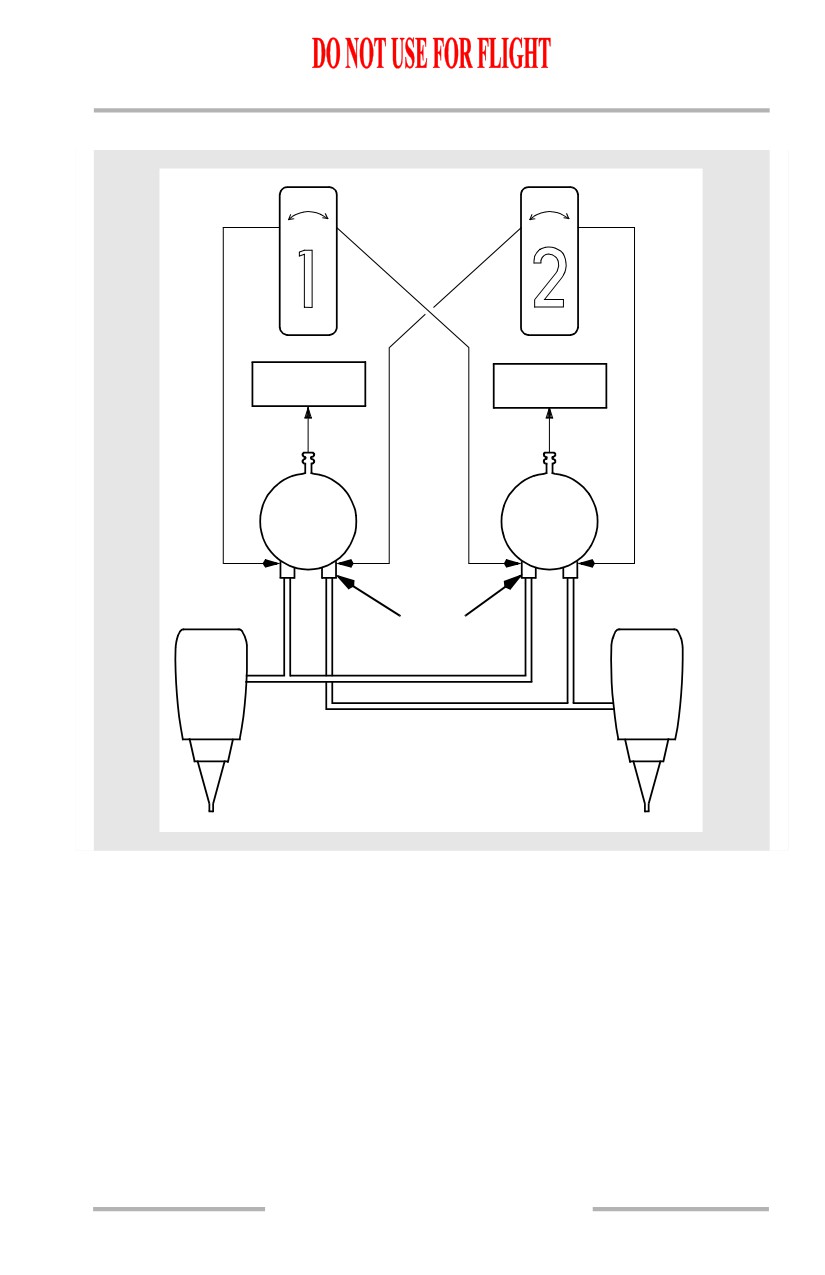
The engine fire extinguisher system consists of two engine fire extinguisher
bottles, two engine fire warning switches, two BOTTLE DISCHARGE lights, and
an EXT TEST switch. Either or both bottles can be discharged into either engine.
The engine fire warning switches are normally locked down to prevent inadvertent
shutdown of an engine. Illumination of an engine fire warning switch or ENG
OVERHEAT light unlocks the engine fire warning switch. The switches may also
be unlocked manually.
Pulling the engine fire warning switch up:
• closes both the engine fuel shutoff valve and the spar fuel shutoff valve
• closes the engine bleed air valve resulting in loss of wing anti-ice to the
affected wing and closure of bleed air operated pack valve
• trips the generator control relay and breaker
• closes the hydraulic fluid shutoff valve. The engine driven hydraulic
pump LOW PRESSURE light is deactivated
• disables thrust reverser for the related engine.
• allows the engine fire warning switch to be rotated for discharge
• arms one discharge squib on each engine fire extinguisher bottle.
Rotating the engine fire warning switch electrically “fires” a squib, discharging
the extinguishing agent into the related engine. Rotating the switch the other way
discharges the remaining bottle.
The L or R BOTTLE DISCHARGE light illuminates a few seconds after the
engine fire warning switch is rotated, indicating the bottle has discharged.
8.20.2
Fire Protection -
System Description
Boeing 737 Operations Manual
Engine Fire Extinguisher Schematic
DISCH
DISCH
L R
L R
L BOTTLE
R BOTTLE
DISCHARGE
DISCHARGE
LEFT
RIGHT
FIRE
FIRE
BOTTLE
BOTTLE
SQUIB
8.20.3
Fire Protection -
System Description
Boeing 737 Operations Manual
APU Fire Protection
APU fire protection consists of these systems:
• APU fire detection powered by the battery bus.
• APU fire extinguishing powered by the hot battery bus.
APU Fire Detection
A single fire detection loop is installed on the APU. As the temperature of the
detector increases to a predetermined limit, the detector senses a fire condition.
The APU fire warning switch remains illuminated until the temperature of the
detector has decreased below the onset temperature.
The system contains a fault monitoring circuit. If the loop fails, the APU DET
INOP light illuminates indicating the APU fire detection system is inoperative.
The indications of an APU fire are:
• the fire warning bell sounds
• both master FIRE WARN lights illuminate
• the APU fire warning switch illuminates
• the APU automatically shuts down
• the wheel well APU fire warning horn sounds, (on the ground only), and
the wheel well APU fire warning light flashes.
APU Fire Extinguishing
The APU fire extinguisher system consists of one APU fire extinguisher bottle, an
APU fire warning switch, an APU BOTTLE DISCHARGE light, and an EXT
TEST switch. The APU ground control panel located in the right main wheel well
also contains an APU fire warning light, an APU BOTTLE DISCHARGE switch,
an APU fire control handle and APU HORN CUTOUT switch.
The APU fire warning switch is normally locked down to prevent inadvertent
shutdown of the APU. Illumination of the APU fire warning switch unlocks the
switch. The switch may also be unlocked manually.
Pulling the APU Fire Warning switch up:
• provides backup for the automatic shutdown feature
• deactivates the fuel solenoid and closes the APU fuel shutoff valve
• closes the APU bleed air valve
• closes the APU air inlet door
• trips the APU generator control relay and breaker
• allows the APU fire warning switch to be rotated for discharge
• arms the APU fire extinguisher bottle squib.
8.20.4
Fire Protection -
System Description
Boeing 737 Operations Manual
Rotating the APU fire warning switch in either direction electrically “fires” the
squib discharging the extinguishing agent into the APU. The APU BOTTLE
DISCHARGE light illuminates after a few seconds, indicating the bottle has
discharged.
Main Wheel Well Fire Protection
Main wheel well fire protection consists of fire detection powered by the No. 1 AC
transfer bus.
Note: The main wheel well has no fire extinguishing system. The nose wheel
well does not have a fire detection system.
Main Wheel Well Fire Detection
A single fire detector loop is installed in the main wheel well. As the temperature
of the detector increases to a predetermined limit, the detector senses a fire
condition. The WHEEL WELL fire warning light remains illuminated until the
temperature of the detector has decreased below the onset temperature.
The indications for a main wheel well fire are:
• the fire warning bell sounds
• both master FIRE WARN lights illuminate
• the WHEEL WELL fire warning light illuminates.
Cargo Compartment Fire Protection
Cargo fire protection consists of these systems:
• cargo compartment smoke detection powered by DC bus 1 and DC bus 2
• cargo compartment fire extinguishing powered by the hot battery bus.
Cargo Compartment Smoke Detection
The forward and aft cargo compartments each have smoke detectors in a dual loop
configuration. Normally, both detection loops must sense smoke to cause an alert.
These loops function in the same manner as the engine overheat/fire detection
loops.
Cargo Compartment Fire Warning
The indications of a cargo compartment fire are:
• the fire warning bell sounds
• both master FIRE WARN lights illuminate
• the FWD/AFT cargo fire warning light(s) illuminates.
8.20.5
Fire Protection -
System Description
Boeing 737 Operations Manual
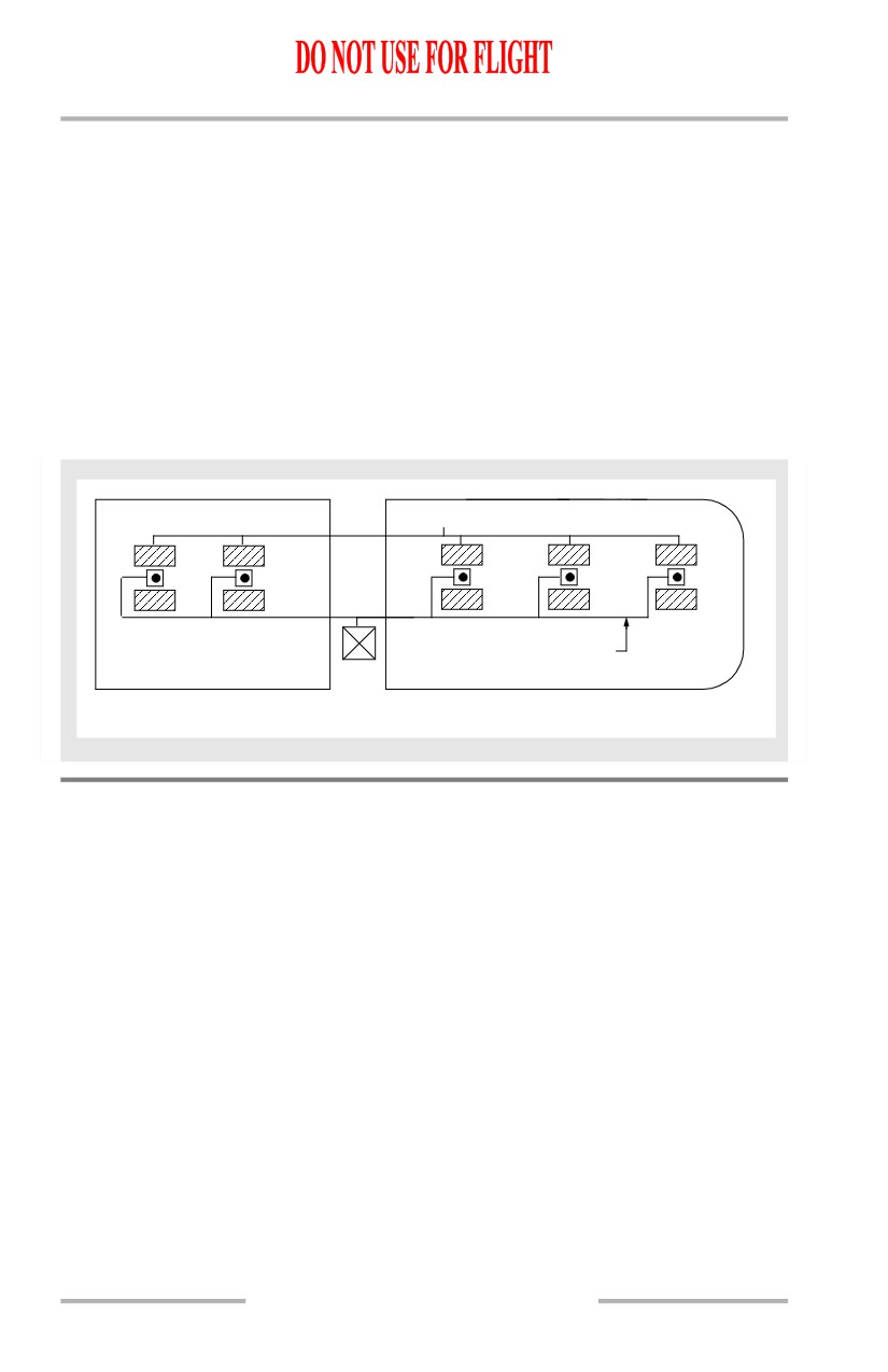
Cargo Compartment Fire Extinguishing
[Option - Single cargo fire extinguisher bottle]
A single fire extinguisher bottle is installed in the air conditioning mix bay on the
forward wing spar. Detection of a fire in either the forward or aft compartment will
cause the FWD or AFT cargo fire warning light to illuminate. The extinguisher is
armed by pushing the appropriate cargo fire ARMED switch. Once armed, the
system is discharged by pushing the cargo fire DISCH switch. This results in the
total discharge of the bottle contents into the selected compartment. The cargo fire
DISCH light illuminates once the bottle is discharged. It may take up to 30
seconds for the light to illuminate.
Cargo Fire Extinguisher Schematic
Dual Loop Area
Smoke Detectors
Discharge Tubing/Nozzles
Fire
Bottle
FWD Cargo Compartment
AFT Cargo Compartment
Lavatory Fire Protection
Lavatory fire protection consists of these systems:
• lavatory smoke detection
• lavatory fire extinguishing (heat activated).
Lavatory Smoke Detection
The lavatory smoke detection system monitors for the presence of smoke. When
smoke is detected:
• an aural warning sounds
• the red alarm indicator light on the lavatory smoke detector panel
illuminates and the appropriate amber lavatory call light will flash
• the amber lavatory SMOKE light on the forward overhead panel
illuminates.
8.20.6
Fire Protection -
System Description
Boeing 737 Operations Manual
Lavatory Fire Extinguisher System
A fire extinguisher system is located beneath the sink area in each lavatory. When
a fire is detected:
• fire extinguisher operation is automatic
• flight deck has no indication of extinguisher discharge.
Fire and Overheat System Tests
The fire and overheat detection systems can be tested by pushing and holding the
FAULT/INOP and OVHT/FIRE TEST switch. Extinguisher continuity can be
tested by pushing and holding the EXT TEST switch. All test indications clear
when switches are released.
FAULT/INOP Test Detection
The fault detection circuits for both the engines and the APU are tested by pushing
and holding the FAULT/INOP and OVHT/FIRE TEST switch in the
FAULT/INOP position.
The indications for the FAULT/INOP test are:
• both MASTER CAUTION lights illuminate
• the OVHT/DET system annunciator light illuminates
• the FAULT light illuminates
• the APU DET INOP light illuminates.
OVERHEAT/FIRE Test Detection
The overheat and fire detection loops on both engines, the APU, and the fire
detector in the wheel well are tested by pushing and holding the FAULT/INOP and
OVHT/FIRE TEST switch in the OVHT/FIRE position.
The indications for the OVHT/FIRE test are:
• the fire warning bell sounds
• both master FIRE WARN lights illuminate
• both MASTER CAUTION lights illuminate
• the OVHT/DET system annunciator light illuminates
• both engine fire warning switches illuminate
• the APU fire warning switch illuminates
• both ENG OVERHEAT lights illuminate
• the WHEEL WELL fire warning light illuminates if AC power is
available
• on the ground, the wheel well APU fire warning horn sounds and the
wheel well APU fire warning light flashes.
8.20.7