Boeing 737 - 600/700/800/900. Operations Manual (1997 year) - page 37
Engines, APU -
General Controls and Indicators
Boeing 737 Operations Manual
• if light is illuminated when APU switch is placed to OFF, light
extinguishes after 5 minutes
• light is disarmed when the APU switch is in OFF position.
4
APU FAULT Light
Illuminated (amber) -
• a malfunction exists causing APU to initiate an automatic shutdown
• if light is illuminated when APU switch is placed to OFF, light
extinguishes after 5 minutes
• light is disarmed when APU switch is in OFF position.
5
APU LOW OIL PRESSURE Light
Illuminated (amber) -
• during start until the APU oil pressure is normal
• oil pressure is low causing an automatic shutdown (after start cycle is
complete)
• if light is illuminated when APU switch is placed to OFF, light
extinguishes after 5 minutes
• light is disarmed when APU switch is in OFF position.
6
APU Switch
OFF - normal position when APU is not running
• positioning switch to OFF with APU running trips APU generator off the
bus(es), if connected, and closes APU bleed air valve. APU continues to
run for a 60 second cooling period
• APU air inlet door automatically closes after shutdown.
ON - normal position when APU is running.
START (momentary) - positioning APU switch from OFF to START and
releasing it to ON, initiates an automatic start sequence.
7.15.8
Boeing 737 Operations Manual
Engines, APU
Chapter 7
Engine System Description
Section 20
Introduction
The airplane is powered by two CFM56-7 engines. The engine is a dual-rotor,
axial-flow turbofan. The N1 rotor consists of a fan, a low-pressure compressor
and a low-pressure turbine. The N2 rotor consists of a high-pressure compressor
and a high-pressure turbine. The N1 and N2 rotors are mechanically independent.
The N2 rotor drives the engine gearboxes. A bleed-air-powered starter motor is
connected to the N2 rotor.
A dual-channel electronic engine control (EEC) regulates each engine. The EEC
monitors autothrottle and flight crew inputs to automatically set engine thrust.
Each engine has individual flight deck controls. Thrust is set by positioning the
thrust levers. The thrust levers are positioned automatically by the autothrottle
system or manually by the flight crew. The forward thrust levers control forward
thrust from idle to maximum. The reverse thrust levers control thrust from reverse
idle to maximum reverse.
Engine Indications
[Option - Side by side display]
Engine indications are displayed on the center instrument panel upper display unit
(DU). If a failure is detected on the upper DU, the engine indications
automatically shift to the lower DU. The engine indications can also be manually
selected to either the Captain’s or First Officer’s inboard DU, or the lower DU,
using the respective display select panel.
N1, EGT, N2, and FF/FU are the primary indications and are displayed as both
digital readouts and round dial/moving pointer indications. N1, EGT, and N2 have
operating limits indicated by redlines. EGT also displays an amber caution limit.
If one of these indications exceeds the red or amber line, the digital readout, box,
pointer, and indicator change color to red or amber.
Oil pressure, oil temperature, oil quantity, and engine vibration are the secondary
engine indications. Oil pressure and oil temperature indications are displayed with
a round dial/moving pointer. Operating and caution ranges are displayed with red
and amber lines. If the red or amber line is reached, the pointer changes color to
red or amber for that indication. The oil quantity indicator displays a digital
readout of quantity as a percent of full.
Engine vibration indications are displayed with a round dial/moving pointer.
7.20.1
Engines, APU -
Engine System Description
Boeing 737 Operations Manual
The EEC must receive electrical power to supply engine operating data to the
flight deck engine indications. When the EEC is not powered, N1, N2, oil quantity
and engine vibration are displayed directly from the engine sensors. Positioning
the engine start switch to GRD supplies electrical power to the EEC and displays
pointers/digits for all engine parameters.
During battery start with no power on the airplane, only N1, N2, and oil quantity
are available. The EEC is not powered until the engine accelerates to a speed
greater than 15% N2. At 15% N2, the EEC becomes energized and pointers/digits
for all engine parameters are displayed.
An engine failure alert indication (ENG FAIL) is displayed in amber on the EGT
indicator when the respective engine is operating at a condition below sustainable
idle (50% N2) and the engine start lever is in the IDLE position. The alert remains
until the engine recovers, the engine start lever is moved to CUTOFF, or the
engine fire warning switch is pulled.
Engine Indications
[Option - Over/Under display]
Primary and secondary engine indications are provided. Engine indications are
displayed on the center forward panel upper display unit (DU), lower DU or the
Captain’s or First Officer’s inboard DU.
Primary Engine Indications
N1 and EGT are the primary engine indications. The primary engine indications
are normally displayed on the center forward panel upper DU. If that unit fails, the
display automatically moves to the lower DU. The primary engine indications can
also be manually selected to either the Captain’s or First Officer’s inboard DU, or
the lower DU, using the respective display select panel.
Secondary Engine Indications
[Option - Fuel flow displayed full time]
N2, fuel flow, oil pressure, oil temperature, oil quantity, and engine vibration are
the secondary engine indications. The secondary engine indications, except for
fuel flow, are manually selected to either the Captain’s or First Officer’s inboard
DU, or the lower DU, using the respective display select panel and the ENG
switch on the engine display control panel. Fuel flow is displayed full time on the
upper display unit below the primary engine indications.
The secondary engine indications are automatically displayed when:
• the displays initially receive electrical power
• in flight when an engine start lever is moved to CUTOFF
• in flight when an engine N2 RPM is below idle
• a secondary engine parameter is exceeded.
7.20.2
Engines, APU -
Engine System Description
Boeing 737 Operations Manual
When the secondary engine indications are automatically displayed, they cannot
be cleared until the condition is no longer present.
Normal Display Format
N1, EGT, and N2 are displayed as both digital readouts and round dial/moving
pointer indications. The digital readouts display numerical values while the
moving pointers indicate relative value.
Oil pressure, oil temperature, and engine vibration indications are both digital
readouts and vertical indication/moving pointers. Fuel flow and oil quantity are
digital readouts only. All digital readouts are enclosed by boxes.
The dials and vertical indications display the normal operating range, caution
range, and operating limits.
Normal operating range is displayed on a dial or vertical indication in white.
N1, EGT, and N2 have operating limits indicated by redlines. EGT also displays
an amber caution limit. If one of these indications exceeds the red or amber line,
the digital readout, box, pointer, and indicator change color to red or amber.
The oil temperature and oil pressure vertical indications have a caution range and
an operating limit redline. If the oil temperature or pressure reaches the caution
range, the digital readout, digital readout box, and pointer all change color to
amber. If one of these indications reach the operating limit, the digital readout,
digital readout box, and pointer all change color to red.
The EEC must receive electrical power to supply engine operating data to the
flight deck engine indications. When the EEC is not powered, N1, N2, oil quantity
and engine vibration are displayed directly from the engine sensors. Positioning
the engine start switch to GRD supplies electrical power to the EEC and displays
pointers/digits for all engine parameters.
During battery start with no power on the airplane, only N1, N2, and oil quantity
are available. The EEC is not powered until the engine accelerates to a speed
greater than 15% N2. At 15% N2, the EEC becomes energized and pointers/digits
for all engine parameters are displayed.
An engine failure alert indication (ENG FAIL) is displayed in amber on the EGT
indicator when the respective engine is operating at a condition below sustainable
idle (50% N2) and the engine start lever is in the IDLE position. The alert remains
until the engine recovers, the engine start lever is moved to CUTOFF, or the
engine fire warning switch is pulled.
7.20.3
Engines, APU -
Engine System Description
Boeing 737 Operations Manual
Compact Display
In compact format, the primary and secondary engine indications are combined on
the same display. The N1 and EGT indications are displayed as they are normally.
All other indications change to digital readouts only. N2, oil temperature, and oil
pressure digital readouts turn red or amber if an exceedance occurs. The N2 digital
display is framed with a red box after engine shutdown on the ground if an inflight
exceedance occurred.
Primary and secondary engine indications are displayed in compact format on the
upper DU when the secondary engine indications are selected for display
(manually or automatically) and the lower DU is unavailable. Alternatively, the
compacted indications are displayed on the lower DU if the upper DU is
unavailable.
Electronic Engine Control (EEC)
Each engine has a full authority digital EEC. Each EEC has two independent
control channels, with automatic channel transfer if the operating channel fails.
With each engine start or start attempt, the EEC alternates between control
channels. The EEC uses thrust lever inputs to automatically control forward and
reverse thrust. N1 is used by the EEC to set thrust in two control modes: normal
and alternate. Manual selection of the control mode can be made with the EEC
switches on engine panel.
EEC Normal Mode
In the normal mode, the EEC uses sensed flight conditions and bleed air demand
to calculate N1 thrust ratings. The EEC compares commanded N1 to actual N1
and adjusts fuel flow to achieve the commanded N1.
The full rated takeoff thrust for the installed engine is available at a thrust lever
position less than the forward stop. Fixed or assumed temperature derated takeoff
thrust ratings are set at thrust lever positions less than full rated takeoff. If the
thrust lever is advanced to the forward stop, the EEC limits thrust to the maximum
thrust rating offered for the airplane model.
The standard reserve thrust rating available at the forward stop varies according
to fleet configuration as follows:
[737-600]
• CFM56-7B22 rating
[737-700]
• CFM56-7B24 rating
[737-800/900, BBJ/BBJ-2]
• CFM56-7B27 rating
7.20.4
Engines, APU -
Engine System Description
Boeing 737 Operations Manual
Takeoff Bump Thrust
[Option - Takeoff bump thrust]
Takeoff bump thrust is available when increased thrust is needed for takeoff,
above the normal maximum takeoff thrust setting. When selected using the FMC
N1 LIMIT page, takeoff thrust is increased by either the flight crew or the
autothrottle positioning the thrust levers to set N1 to the reference N1 bug. Bump
thrust applies only to the takeoff rating; maximum climb, maximum continuous
and go-around thrust ratings are not affected.
Airplanes equipped with a takeoff thrust bump have a reserve thrust capability
which is greater than the standard values listed under the EEC Normal Mode listed
above. Use of this reserve thrust capability is intended for emergency use only in
the event of wind shear or impending ground contact.
FMC selection of takeoff bump thrust can be configured as either “Bump Option”
or a “Full-Rate Option.” When configured as a FMC “Bump Option”, the default
takeoff rating is lower then takeoff bump, and the takeoff bump must be activated
via the FMC-CDU. With this “Bump Option” configuration, assumed temperature
engine derates are not available from the bump. When configured as a FMC
“Full-Rate Option”, the default takeoff rating is the takeoff bump. With this
full-rate option, the assumed temperature engine derate method may always be
used. With this “Full-Rate Option” configuration, the ability to select the lowest
normally offered takeoff fixed derate is lost.
EEC Alternate Mode
The EEC can operate in either of two alternate modes, soft or hard. If required
signals are not available to operate in the normal mode, the EEC automatically
changes to the soft alternate mode. When this occurs, the ALTN switch
illuminates and the ON indication remains visible. In the soft alternate mode, the
EEC uses the last valid flight conditions to define engine parameters which allows
the mode change to occur with no immediate change in engine thrust. Thrust
rating shortfalls or exceedances may occur as flight conditions change. The soft
alternate mode remains until the hard alternate mode is entered by either retarding
the thrust lever to idle or manually selecting ALTN with the EEC switch on the aft
overhead panel.
Note: Loss of either DEU results in a loss of signal to both EECs. The EEC
ALTN lights illuminate and each EEC reverts to the alternate mode to
prevent the engines from operating on a single source of data.
7.20.5
Engines, APU -
Engine System Description
Boeing 737 Operations Manual
When the hard alternate mode is entered, the EEC reverts to the alternate mode
thrust schedule. Hard alternate mode thrust is always equal to or greater than
normal mode thrust for the same lever position. If the hard alternate mode is
entered by reducing the thrust lever to idle while in the soft alternate mode, the
ALTN switch remains illuminated and the ON indication remains visible. When
ALTN is selected manually, the ON indication is blanked.
Structural Limit Protection
The EEC provides N1 and N2 redline overspeed protection in both normal and
alternate modes. The EGT limit must be observed by the crew because the EEC
does not provide EGT redline exceedance protection.
Idle Operation
The EEC automatically selects ground minimum idle, flight minimum idle, and
approach idle. Ground minimum idle is selected for ground operations and flight
minimum idle is selected for most phases of flight. Approach idle is selected in
flight if flaps are in landing configuration or engine anti-ice is ON for either
engine. At the same airspeed and altitude, N1 and N2% RPM will be higher for
approach idle than for flight minimum idle. This higher% RPM improves engine
acceleration time in the event of a go-around. Approach idle is maintained until
after touchdown, when ground minimum idle is selected. In flight, if a fault
prevents the EEC from receiving flap or anti-ice signals, approach idle schedule
begins below 15,000 feet MSL.
7.20.6
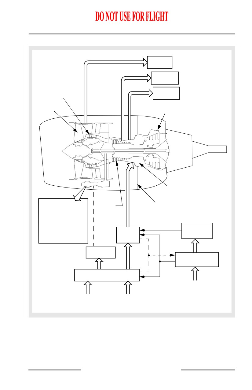
Engines, APU -
Engine System Description
Boeing 737 Operations Manual
Power Plant Schematic
FAN AIR
5TH STAGE
BLEED AIR
LOW
PRESSURE
9TH STAGE
COMPRESSOR
BLEED AIR
FAN
TURBINES
COMBUSTOR
ACCESSORIES
THRUST REVERSER
HIGH
OIL PUMP
PRESSURE
COMPRESSOR
FUEL PUMPS
INTEGRATED DRIVE
GENERATOR
ELECTRONIC
ENGINE
ENGINE
STARTER
FUEL
CONTR0L
HYDRAULIC PUMP
SYSTEM
AIR DRIVEN
STARTER
FLIGHT DECK
CONTROLS
& INDICATORS
ENGINE START
& IGNITION SYSTEM
FROM
ELECTRICAL
SYSTEM
FROM
FROM
BLEED AIR
FUEL
SYSTEM
SYSTEM
7.20.7
Engines, APU -
Engine System Description
Boeing 737 Operations Manual
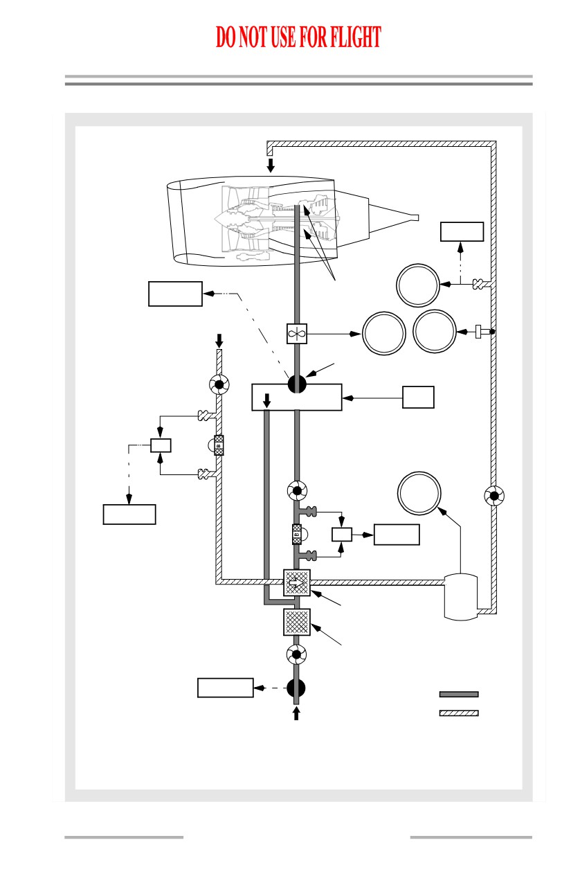
Engine Fuel System
Fuel is delivered under pressure from fuel pumps located in the fuel tanks. The
fuel flows through a fuel spar shutoff valve located at the engine mounting wing
stations. The fuel passes through the first stage engine fuel pump where pressure
is increased. It then passes through two fuel/oil heat exchangers where IDG oil and
main engine oil heat the fuel. A fuel filter then removes contaminants. Fuel
automatically bypasses the filter if the filter becomes saturated. Before the fuel
bypass occurs, the fuel FILTER BYPASS alert illuminates on the fuel control
panel. The second stage engine fuel pump adds more pressure before the fuel
reaches the hydro mechanical unit (HMU). To meet thrust requirements, the EEC
meters fuel through the HMU.
The spar fuel shutoff valve and engine fuel shutoff valve allow fuel flow to the
engine when both valves are open. The valves are open when the engine fire
warning switch is in and the start lever is in IDLE. Both valves close when either
the start lever is in CUTOFF or the engine fire warning switch is out. SPAR
VALVE CLOSED and ENG VALVE CLOSED lights located on the overhead
panel indicate valve position.
Fuel flow is measured after passing through the engine fuel shutoff valve and is
displayed on the display unit. Fuel flow information is also provided to the FMS.
Engine Oil System
Oil from the individual engine tank is circulated under pressure, through the
engine to lubricate the engine bearings and accessory gearbox. The oil quantity
indicator, oil temperature indicator, oil pressure indicator and LOW OIL
PRESSURE alert are all located on the display unit.
The oil system is pressurized by the engine driven oil pump. Oil from the pump,
goes to the engine bearings and gearbox. Sensors for the oil temperature indicator,
oil pressure indicator and LOW OIL PRESSURE alert are located downstream of
the oil pump prior to engine lubrication.
Oil is returned to the oil tank by engine driven scavenge pumps. From the
scavenge pumps oil passes through a scavenge filter. If the filter becomes
saturated with contaminants, oil automatically bypasses the filter. Prior to the oil
bypassing the scavenge filter, the OIL FILTER BYPASS alert illuminates on the
upper display unit.
Prior to returning to the oil tank, the oil passes through the main engine oil cooler
where it is cooled by engine fuel to maintain proper oil temperature.
7.20.8
Engines, APU -
Engine System Description
Boeing 737 Operations Manual
Engine Fuel and Oil System Schematic
TO BEARINGS
AND GEAR BOXES
LOW OIL
PRESSURE
VIA
EEC
OIL
ENG VALVE
COMBUSTOR
PRESS
VIA
CLOSED
EEC
FUEL FLOW
OIL
TRANSMITTER
RETURN
VIA EEC
FUEL
OIL
FLOW
TEMP
VIA
EEC
ENGINE FUEL
SCAVENGE
SHUTOFF VALVE
PUMPS
EEC
HMU
SCAVENGE
C
FILTER
VIA
EEC
SECOND
STAGE
OIL
OIL
FUEL PUMP
QUANT
PUMP
OIL FILTER
BYPASS
FILTER
FUEL
C
BYPASS
FILTER
VIA
EEC
B
OIL
MAIN ENGINE
TANK
OIL COOLER
IDG FUEL-COOLED
FIRST STAGE
OIL COOLER
FUEL PUMP
SPAR VALVE
SPAR FUEL
CLOSED
SHUTOFF VALVE
FUEL
NOTE:
OIL
ALL ENGINE OIL AND FUEL
FROM FUEL TANK
INDICATIONS (EXCEPT OIL
QUANTITY AND ENGINE VALVE
CONDITION:
CLOSED) ARE SENSED BY THE
OPERATION
EEC, DIGITIZED, AND SENT
NORMAL ENGINE
TO THE CDS.
7.20.9
Engines, APU -
Engine System Description
Boeing 737 Operations Manual
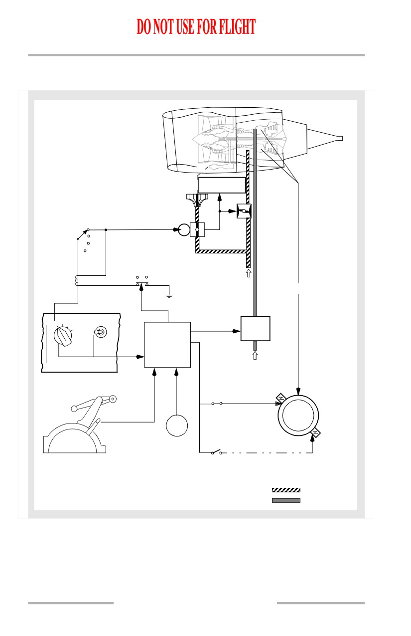
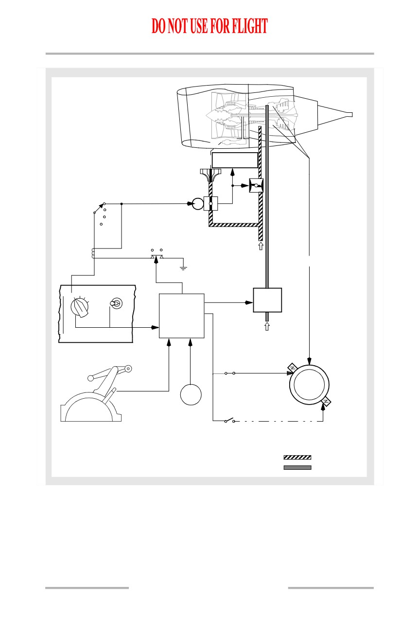
Engine Start System
Starter operation requires pressurized air and electrical power. Air from the bleed
air system powers the starter motor. The APU, an external ground cart, or the other
operating engine provides the bleed air source.
In the GRD position, the engine start switch uses battery power to close the engine
bleed air valve and open the start valve to allow pressure to rotate the starter. When
the start valve opens, an amber START VALVE OPEN alert is provided on the
upper display unit. The starter rotates the N2 compressor through the accessory
drive gear system. When the engine accelerates to the recommended value (25%
N2 or max motoring), moving the engine start lever to the IDLE position opens
the fuel valves on the wing spar and engine, and causes the EEC to supply fuel and
ignition to the combustor where the fuel ignites. Initial fuel flow indications lag
actual fuel flow by approximately two seconds, therefore, during engine start, an
EGT rise may occur before fuel flow indication.
[Option - Without automatic ignition]
At starter cutout speed (approximately 56% N2), power is removed from the start
switch holding solenoid. The engine start switch returns to OFF, the engine bleed
air valve returns to the selected position, and the start valve closes.
[Option - With automatic ignition]
At starter cutout speed (approximately 56% N2), power is removed from the start
switch holding solenoid. The engine start switch returns to AUTO, the engine
bleed air valve returns to the selected position, and the start valve closes.
Abnormal Start Protection (Ground Starts Only)
During ground starts, the EEC monitors engine parameters to detect impending
hot starts, EGT start limit exceedances, and wet starts. These protection features
do not function during inflight starts.
If an impending hot start is detected by a rapid rise in EGT or EGT approaching
the start limit, the white box surrounding the EGT digital readout flashes. The
flashing white box resets when the start lever is moved to CUTOFF or the engine
reaches idle N2.
If the EGT exceeds the starting limit, the EGT display, both box and dial, turn red.
The EEC automatically turns off the ignition and shuts off fuel to the engine. The
alert terminates and the display returns to white when EGT drops below the start
limit. Following engine shutdown, the EGT box turns red to remind the crew of
the exceedance.
A wet start occurs if the EGT does not rise after the start lever is moved to IDLE.
If a wet start is detected, the EEC turns off the ignition and shuts off fuel to the
engine 15 seconds after the start lever is moved to IDLE.
7.20.10
Engines, APU -
Engine System Description
Boeing 737 Operations Manual
Engine Ignition System
Each engine has two igniter plugs. The EEC arms the igniter plug(s) selected by
the ignition select switch. The left igniter plug receives power from the associated
AC transfer bus. The right igniter plug receives power from the AC standby bus.
Auto-Relight
An auto-relight capability is provided for flameout protection. Whenever the EEC
detects an engine flameout, both igniters are activated. A flameout is detected
when an uncommanded rapid decrease in N2 occurs, or N2 is below idle RPM.
Inflight Starting
Two methods of starting an engine inflight are available, windmill and crossbleed.
None of the ground start protection features are functional during inflight start.
Note: At low N2 values, the oil scavenge pump may not provide enough pressure
to return oil to the tank, causing a low oil quantity indication. Normal oil
quantity should be indicated after start.
[Option - Side by side display]
If crossbleed starting is required, the X-BLD START indication is displayed
above the N2 dial. This indication is based on airplane altitude, airspeed and N2.
[Option - Over/Under display]
If crossbleed starting is required, the X-BLD indication (XB for the compact
engine display) is displayed above the N2 dial. This indication is based on airplane
altitude, airspeed and N2.
7.20.11
Engines, APU -
Engine System Description
Boeing 737 Operations Manual
Engine Start and Ignition System Schematic
[Option - Without automatic ignition]
START VALVE
AIR DRIVEN
OPEN
STARTER
ENGINE
BLEED AIR
VALVE
GRD
S
OFF
START
CONT
VALVE
FLT
STARTER
SWITCH
HIGH N
2
CUTOUT
HOLDING
SWITCH
FROM BLEED
RELAY
AIR SYSTEM
COMBUSTOR
LOW N
2
ENGINE START
GRDOFF
CONT
BOTH
FLT
IGN
IGN
HMU
L
R
ELECTRONIC
ENGINE
1
CONTROL
FROM FUEL
SYSTEM
LEFT
IGNITER
IDLE
N2
RIGHT
IGNITER
CUTOFF
CONDITION:
ENGINE BEING STARTED
BLEED AIR
N2 ROTATION BELOW STARTER CUTOUT SPEED.
FUEL
7.20.12
Engines, APU -
Engine System Description
Boeing 737 Operations Manual
[Option - With automatic ignition]
START VALVE
AIR DRIVEN
OPEN
STARTER
ENGINE
BLEED AIR
VALVE
GRD
S
AUTO
START
CONT
VALVE
FLT
STARTER
SWITCH
HIGH N
2
CUTOUT
HOLDING
SWITCH
FROM BLEED
RELAY
LOW N
AIR SYSTEM
COMBUSTOR
2
ENGINE START
GRDAUTOCONT
BOTH
FLT
IGN
IGN
HMU
L
R
ELECTRONIC
ENGINE
1
CONTROL
FROM FUEL
SYSTEM
LEFT
IGNITER
IDLE
N2
RIGHT
IGNITER
CUTOFF
CONDITION:
BLEED AIR
ENGINE BEING STARTED
N2 ROTATION BELOW STARTER CUTOUT SPEED.
FUEL
Engines, APU -
Engine System Description
Boeing 737 Operations Manual
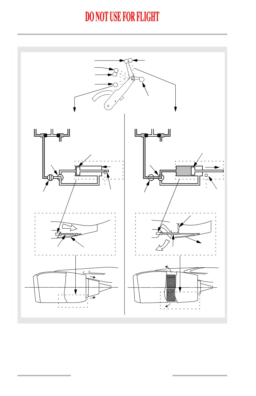
Thrust Reverser
Each engine is equipped with a hydraulically operated thrust reverser, consisting
of left and right translating sleeves. Aft movement of the reverser sleeves causes
blocker doors to deflect fan discharge air forward, through fixed cascade vanes,
producing reverse thrust. The thrust reverser is for ground operations only and is
used after touchdown to slow the airplane, reducing stopping distance and brake
wear.
Hydraulic pressure for the operation of engine No. 1 and engine No. 2 thrust
reversers comes from hydraulic systems A and B, respectively. If hydraulic
system A and/or B fails, alternate operation for the affected thrust reverser is
available through the standby hydraulic system. When the standby system is used,
the affected thrust reverser deploys and retracts at a slower rate and some thrust
asymmetry can be anticipated.
The thrust reverser can be deployed when either radio altimeter senses less than
10 feet altitude, or when the air/ground safety sensor is in the ground mode.
Movement of the reverse thrust levers is mechanically restricted until the forward
thrust levers are in the idle position.
When reverse thrust is selected, an electro-mechanical lock releases, the isolation
valve opens and the thrust reverser control valve moves to the deploy position,
allowing hydraulic pressure to unlock and deploy the reverser system. An
interlock mechanism restricts movement of the reverse thrust lever until the
reverser sleeves have approached the deployed position. When either reverser
sleeve moves from the stowed position, the amber REV indication, located on the
upper display unit, illuminates. As the thrust reverser reaches the deployed
position, the REV indication illuminates green and the reverse thrust lever can be
raised to detent No. 2. This position provides adequate reverse thrust for normal
operations. When necessary, the reverse thrust lever can be pulled beyond detent
No. 2, providing maximum reverse thrust.
Downward motion of the reverse thrust lever past detent No. 1 (reverse idle thrust)
initiates the command to stow the reverser. When the lever reaches the full down
position, the control valve moves to the stow position allowing hydraulic pressure
to stow and lock the reverser sleeves. After the thrust reverser is stowed, the
isolation valve closes and the electro-mechanical lock engages.
7.20.14
Engines, APU -
Engine System Description
Boeing 737 Operations Manual
The REVERSER light, located on the aft overhead panel, illuminates when the
thrust reverser is commanded to stow and extinguishes 10 seconds later when the
isolation valve closes. Any time the REVERSER light illuminates for more than
approximately
12 seconds, a malfunction has occurred and the MASTER
CAUTION and ENG system annunciator lights illuminate.
Note: A pause in movement of the reverse thrust levers past detent No. 1 toward
the stow position may cause MASTER CAUTION and ENG system
annunciator lights to illuminate. A pause of approximately 16 seconds
engages the electro-mechanical lock and prevents the thrust reverser
sleeves from further movement. Cycling the thrust reversers may clear the
fault and restore normal operation.
When the reverser sleeves are in the stow position, an electro-mechanical lock
and a hydraulically operated locking actuator inhibit motion to each reverser
sleeve until reverser extension is selected. Additionally, an auto-restow circuit
compares the actual reverser sleeve position and the commanded reverser
position. In the event of incomplete stowage or uncommanded movement of the
reverser sleeves toward the deployed position, the auto-restow circuit opens the
isolation valve and commands the control valve to the stow position directing
hydraulic pressure to stow the reverser sleeves. Once the auto-restow circuit is
activated, the isolation valve remains open and the control valve is held in the
stowed position until the thrust reverser is commanded to deploy or until
corrective maintenance action is taken.
WARNING: Actuation of the thrust reversers on the ground without
suitable precautions is dangerous to ground personnel.
7.20.15
Engines, APU -
Engine System Description
Boeing 737 Operations Manual
Thrust Reverser Schematic
DETENT NO. 2
MAXIMUM REVERSE THRUST
DETENT NO. 1
INTERLOCK
STOWED
FORWARD
THRUST
LEVER
REVERSE THRUST (STOWED)
REVERSE THRUST (DEPLOYED)
SYSTEM
STANDBY
SYSTEM
SYSTEM
STANDBY
SYSTEM
A
SYSTEM
B
A
SYSTEM
B
ENGINE 1
ENGINE 2
ENGINE 1
ENGINE 2
SYSTEM A
SYSTEM B
SYSTEM A
SYSTEM B
HYDRAULIC
HYDRAULIC
HYDRAULIC
HYDRAULIC
ACTUATOR
PRESSURE
PRESSURE
PRESSURE
PRESSURE
CONTROL
ACTUATOR
CONTROL
VALVE
VALVE
(STOW)
STOWED AND
(DEPLOY)
DEPLOY
LOCKED
ELECTRO-
ELECTRO-
ISOLATION
MECHANICAL
ISOLATION
MECHANICAL
VALVE
LOCK
VALVE
LOCK
(CLOSED)
(OPEN)
(LOCKED)
(UNLOCKED)
BLOCKER
DOOR
FAN FLOW
FAN FLOW
TRANSLATING
CASCADE
TRANSLATING
CASCADE
SLEEVE
VANES
SLEEVE
VANES
7.20.16
Boeing 737 Operations Manual
Engines, APU
Chapter 7
APU System Description
Section 30
Introduction
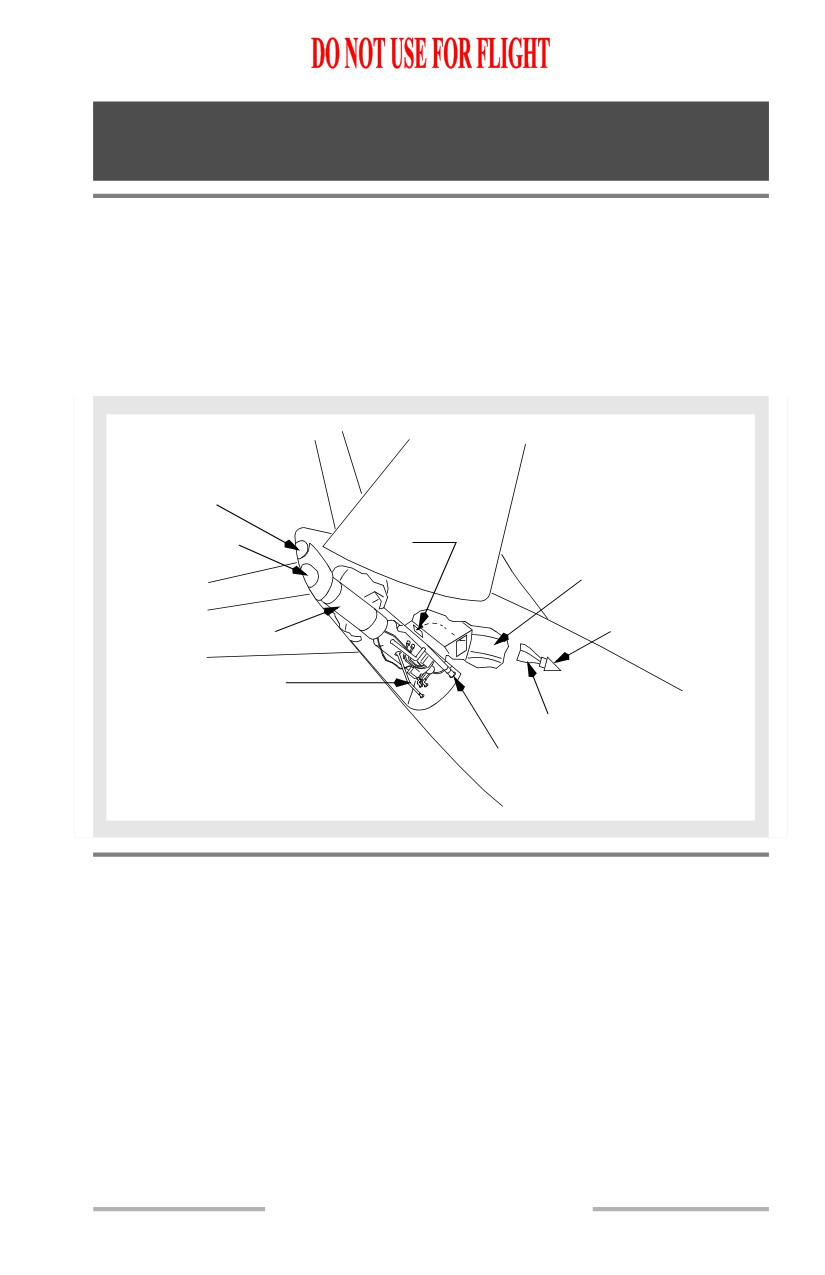
The auxiliary power unit (APU) is a self-contained gas turbine engine installed
within a fireproof compartment located in the tail of the airplane.
The APU supplies bleed air for engine starting or air conditioning. An AC
electrical generator on the APU provides an auxiliary AC power source.
APU Location
COOLING AIR
INLET
EXHAUST OUTLET
APU DUCT
AIR DIFFUSER DUCT
EXHAUST MUFFLER
VORTEX GENERATOR
APU FUEL LINE
AIR INLET DOOR
APU BLEED
AIR DUCT
APU Operation
The APU starts and operates up to the airplane maximum certified altitude.
The APU supplies bleed air for both air conditioning packs on the ground or one
pack in flight. Both transfer busses can be powered on the ground or in flight.
7.30.1
Engines, APU -
APU System Description
Boeing 737 Operations Manual
APU Fuel Supply
[Option - APU DC fuel boost pump]
Fuel to start and operate the APU comes from the left side of the fuel manifold
when the AC fuel pumps are operating. A DC operated APU fuel boost pump is
installed to ensure positive fuel pressure to the APU fuel control unit. During APU
start and operation, the pump operates automatically when the APU fuel control
unit senses low fuel pressure. The pump shuts off automatically when an AC fuel
pump pressurizes the fuel manifold. If the AC and DC fuel pumps are not
operating, fuel is suction fed from the No. 1 tank. During APU operation, fuel is
automatically heated to prevent icing.
APU Engine and Cooling Air
APU engine air routes to the APU through an automatically operated air inlet door
located on the right side of the fuselage. APU exhaust gases discharge overboard
through an exhaust muffler.
Air for APU cooling enters through a cooling air inlet above the APU exhaust
outlet. This air circulates through the APU compartment, passes through the oil
cooler and vents through the exhaust outlet.
Electrical Requirements for APU Operation
APU operation requires the following:
• APU fire switch on the overheat/fire panel must be IN
• APU fire control handle on the APU ground control panel must be IN
• battery switch must be ON.
Electrical power to start the APU comes from No. 1 transfer bus or the airplane
battery(ies). With AC power available, the starter generator uses AC power to start
the APU. With no AC power, the starter generator uses battery power to start the
APU.
Moving the battery switch to OFF on the ground or in the air automatically shuts
down the APU because of power loss to the electronic control unit.
APU Start
The automatic start sequence begins by moving the APU switch momentarily to
START. This initiates opening of the air inlet door. When the APU inlet door
reaches the full open position the start sequence begins. After the APU reaches the
proper speed, ignition and fuel are provided. When the APU is ready to accept a
bleed air or electrical load the APU GEN OFF BUS light illuminates.
Note: When the APU is started using battery power only, there is no indication
on the electrical metering panel that the APU generator has come on line
and is ready to be selected. Both the frequency and voltage readings are
zero until the APU generator is placed on line.
7.30.2
Engines, APU -
APU System Description
Boeing 737 Operations Manual
If the APU does not reach the proper speed with the proper acceleration rate within
the time limit of the starter, the start cycle automatically terminates. The start cycle
may take as long as 120 seconds. Automatic shutdown occurs in the event of EGT
exceedance.
If the start fails or the APU GEN OFF BUS light fails to illuminate by the end of
the start cycle, a system failure has occurred and the FAULT light illuminates.
Operate the APU for one full minute before using it as a bleed air source. This one
minute stabilization is recommended to extend the service life of the APU.
APU Shutdown
Operate the APU for one full minute with no bleed air load prior to shutdown. This
cooling period is recommended to extend the service life of the APU. When the
APU switch is moved to OFF, this time delay is met automatically.
Moving the APU switch to OFF trips the APU generator, closes the APU bleed air
valve and extinguishes the APU GEN OFF BUS light. Shutdown occurs
automatically after
60 seconds. When the APU speed decreases sufficiently
during shutdown, the fuel valve and inlet door close. If the fuel valve does not
close, the FAULT light will illuminate after approximately 30 seconds. An
immediate shutdown can be accomplished by pulling the APU fire switch.
Electronic Control Unit (ECU)
An electronic control unit (ECU) monitors and controls the APU. Automatic
shutdown protection is provided for overspeed conditions, low oil pressure, high
oil temperature, APU fire, fuel control unit failure, EGT exceedance, and other
system faults monitored by the ECU.
The ECU automatically controls APU speed through the electronic fuel control. If
speed or EGT exceed acceptable levels with the APU providing electrical load
only, some electrical load is shed. When electrical load and air extraction raise the
EGT above acceptable levels during engine starting, electrical load shedding
occurs prior to reducing bleed air. When electrical load and air extraction raise the
EGT above acceptable levels other than during engine starting, the inlet guide
vanes move toward a closed position, reducing bleed air extraction while
maintaining electrical load.
APU Automatic Load Shedding
In flight, if the APU is the only source of electrical power, all galley busses are
automatically shed. If electrical load still exceeds design limits, both main busses
automatically shed until the load is within design limits. On the ground, the APU
attempts to carry a full electrical load. If an overload condition is sensed, the APU
sheds galley busses first, and then both main busses until the load is within limits.
7.30.3