Boeing 737 - 600/700/800/900. Operations Manual (1997 year) - page 13
Supplementary Procedures -
Flight Instruments, Displays
Boeing 737 Operations Manual
example, if the flap lever is set to 15 for takeoff, a bug for
flaps 5 maneuvering speed will appear. For a flaps 1
takeoff, the flaps 1 maneuvering speed will be displayed.
To set reference airspeed bugs for approach:
Speed reference selector (outer)
WT
Default weight of 32,000 kgs / 70,000 lbs is displayed.
Speed reference selector (inner)
Set current gross weight
Flaps up maneuver speed bug is displayed.
Speed reference selector (outer)
VREF
Default speed of 80 knots is displayed.
Speed reference selector (inner)
Set VREF speed
The green VREF bug and white VREF +15 bug are shown when a
speed greater than 80 knots is set.
Note: If V1 or VR is selected in flight, INVALID ENTRY is
displayed.
To set the spare bug, if desired:
Speed reference selector (outer)
Spare bug
Default speed of 60 knots is displayed.
Speed reference selector (inner)
Set
Set speed as desired.
Speed reference selector (outer)
SET
Digital readout is removed.
SP.10.4
Supplementary Procedures -
Flight Instruments, Displays
Boeing 737 Operations Manual
HUD System Procedures
[Option]
HUD system procedures supplement normal procedures and should be
accomplished when applicable.
Flight Deck Preparation
If the HUD will be used for takeoff, or configured for a possible return for landing,
accomplish the following during the flight deck preparation:
HUD System
Set
Combiner - Lowered, cover removed
Runway Data - Set in control panel
Enter runway length
Enter TDZE (if available) or field elevation
Enter glideslope angle for possible return for landing.
Mode - Set
Select IMC or VMC to verify proper alignment
ALIGN HUD light - Extinguished
After checking alignment, set mode as desired.
Note: CLR may be selected to blank display during taxi. Push
CLR again to restore display. If the HUD will not be used
for takeoff, the combiner should be stowed.
For low visibility takeoff, enter ILS frequency and course.
Descent and Approach
If HUD will be used for approach and landing, accomplish the following steps:
Prior to completing the DESCENT-APPROACH checklist:
HUD System
Set
Combiner - Lowered, cover removed
Runway Data - Set in control panel
Enter runway TDZE (if available) or field elevation.
SP.10.5
Supplementary Procedures -
Flight Instruments, Displays
Boeing 737 Operations Manual
Enter glideslope angle.
Mode - Set
Select IMC or VMC to verify proper alignment
ALIGN HUD light - Extinguished
After checking alignment, set mode as desired.
Prior to intercepting final:
Select IMC mode for instrument approach
Select VMC mode for visual approach.
Note: During approach, the first officer will monitor the HUD
ANNUNCIATOR panel.
Landing
If HUD will be used for a CAT II or CAT IIIa approach:
At glideslope capture:
Select/verify AIII mode active.
Shutdown
Accomplish the following step during the Shutdown Procedure:
HUD Combiner
Stowed
If the airplane will be secured, install cover before stowing.
SP.10.6
Supplementary Procedures -
Flight Instruments, Displays
Boeing 737 Operations Manual
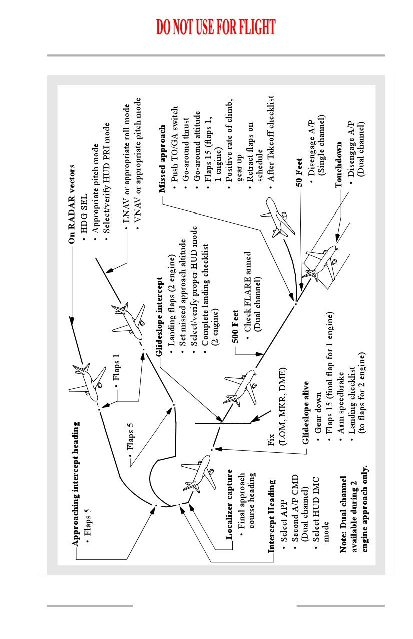
ILS Approach Using HUD
SP.10.7
Supplementary Procedures -
Flight Instruments, Displays
Boeing 737 Operations Manual
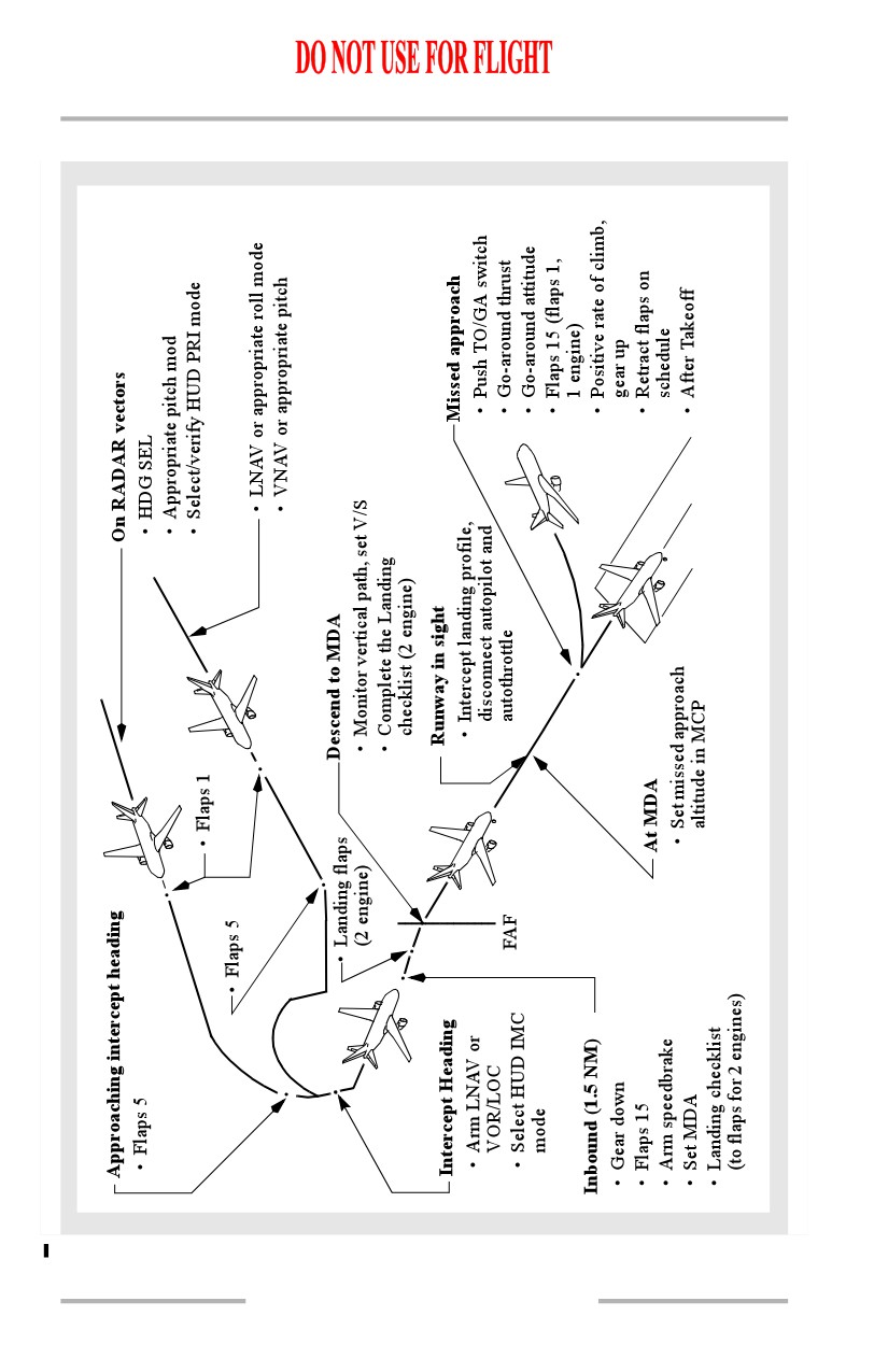
Non-Precision Approach Using HUD
SP.10.8
Supplementary Procedures -
Flight Instruments, Displays
Boeing 737 Operations Manual
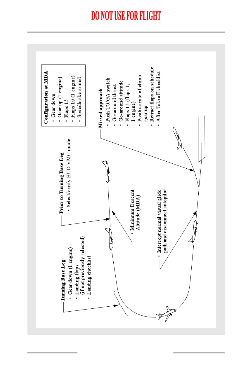
Circling Approach Using HUD
SP.10.9
Supplementary Procedures -
Flight Instruments, Displays
Boeing 737 Operations Manual
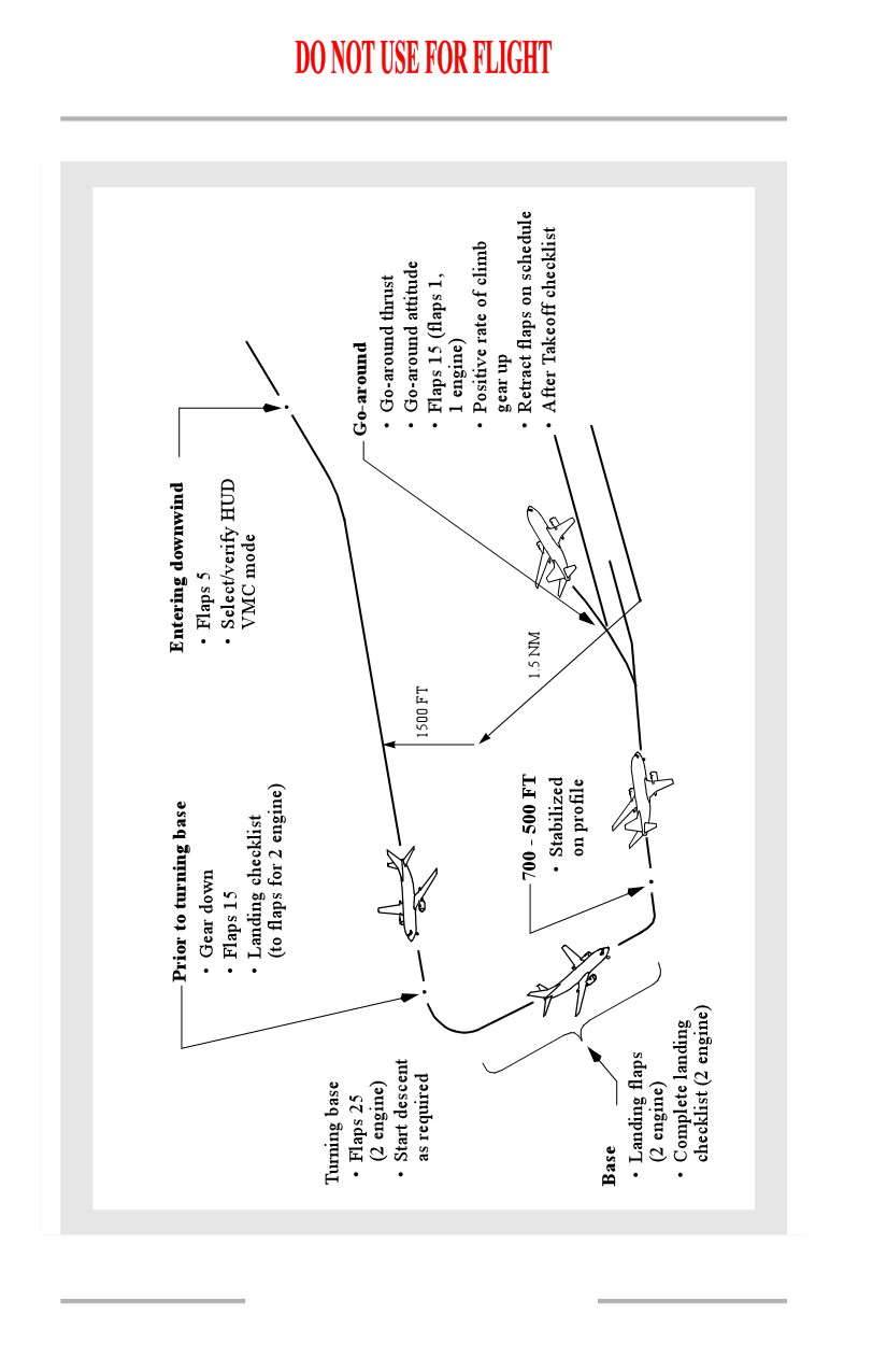
Visual Traffic Pattern Using HUD
SP.10.10
Boeing 737 Operations Manual
Supplementary Procedures
Chapter SP
Flight Management, Navigation
Section 11
Tests
Transponder Test
Transponder mode selector
TEST
Check fail light illuminates.
Check all code segments illuminate. Verify no error codes exist.
Verify aural indicates TCAS system test passed.
Note: TCAS TEST is displayed on the navigation display during
the test followed by TCAS TEST PASSED or TCAS TEST
FAILED. This test remains in view for 8 seconds then
blanks. An aural annunciation sounds at the completion of
the test.
[Option - Allied Signal TCAS computer]
AURAL ALERTS
DEFINITION
“TCAS SYSTEM TEST FAIL”
Test failed. Maintenance required.
“TCAS SYSTEM TEST OK”
Test complete. System operable.
Weather Radar Test
EFIS mode selector
MAP, MAP CTR, VOR, or APP
Weather Radar Mode
TEST
STAB
ON
WXR (EFIS control panel)
ON
Verify test pattern consisting of the following colors appears:
• Green
• Yellow
• Red
• Magenta.
SP.11.1
Supplementary Procedures -
Flight Management, Navigation
Boeing 737 Operations Manual
[Option - With predictive wind shear]
If testing of the PWS system is desired:
Weather Radar Mode
Deselect TEST
WXR (EFIS control panel)
ON
Weather Radar Mode
TEST
Verify the amber WINDSHEAR caution, red WINDSHEAR
warning and PWS FAIL annunciations display momentarily and
then extinquish.
Note: In the short time the weather radar is on and not in the
TEST position, it will radiate.
IRS
Fast Realignment
Prior to commencing procedure the airplane must be parked and not moved until
procedure is complete and ALIGN lights extinguish.
IRS mode selectors
ALIGN
Observe ALIGN lights illuminate steadily.
CDU
Set
Enter present position on SET IRS POS line of the POS INIT page.
IRS mode selector
NAV
Observe ALIGN light extinguished within 30 seconds.
Note: If time permits it is preferable to perform a full alignment of the
IRS. A more precise alignment will result.
Note: If the mode selector is accidentally switched to OFF or ATT,
position mode selector to OFF, wait for ALIGN light(s) to
extinguish, then perform full alignment procedure.
ISDU Entries
Heading Entry
Note: Due to IRS drift rate when in ATT mode, periodic heading
updates are required.
SP.11.2
Supplementary Procedures -
Flight Management, Navigation
Boeing 737 Operations Manual
IRS display selector
HDG
Push H key to initiate a heading entry.
Key-in present magnetic heading. Push ENT key (cue lights extinguish).
Observe proper heading shown on the navigation displays.
Present Position Entry
IRS mode selectors
NAV
ALIGN lights must be illuminated (steady or flashing)
IRS display selector
PPOS
Latitude
Enter
Key-in latitude into data display, beginning with N or S, then push ENT
Key (cue lights extinguish).
Longitude
Enter
Key-in longitude into data display, beginning with E or W, then push ENT
key (cue lights extinguish). Observe proper latitude and longitude are
displayed and ALIGN light is not flashing.
Inadvertent Selection of Attitude Mode (while on the ground)
Inadvertent selection of the attitude mode may be due to physically overpowering
the switch during turn-on or may be the result of a faulty switch which prevents
the flight crew from accurately determining which mode is selected.
If ATT position is selected inadvertently when switching to NAV
IRS mode selectors
OFF
Observe ALIGN lights extinquish.
After ALIGN lights extinquish, initiate a full alignment.
Lateral Navigation (LNAV)
Proceeding Direct to a Waypoint (overwrite)
RTE LEGS page
Select
On page 1/XX, line 1L, enter desired waypoint over the presently
active waypoint.
Correct any ROUTE DISCONTINUITY if entered waypoint was not
in original flight plan.
SP.11.3
Supplementary Procedures -
Flight Management, Navigation
Boeing 737 Operations Manual
[Option - With abeam points]
If abeam waypoints are desired:
ABEAM PTS key
Push
EXEC key
Push
Observe the MOD RTE LEGS page changes to ACT.
Proceeding Direct to a Waypoint (DIR/INTC)
[Option - CDU]
DIR INTC key
Push
Observe DIRECT TO box prompts displayed in line 6L.
Enter desired waypoint on the DIRECT TO line. Observe the
waypoint automatically transfers to line 1L.
Correct any ROUTE DISCONTINUITY if entered waypoint was not
in the original flight plan.
EXEC key
Push
Observe MOD RTE LEGS page changes to ACT.
Intercepting a Leg (Course) to a Waypoint
RTE LEGS page
Select
On page 1/XX, line 1L, enter desired waypoint over presently active
waypoint.
Observe INTC CRS prompt displayed in line 6R.
Enter the desired intercept course in the INTC CRS line. Observe the
desired course is displayed on line 6R but, with magnetic variation
differences in line 1.
Correct any ROUTE DISCONTINUITY if the entered waypoint was
not in original flight plan.
EXEC key
Push
Observe MOD RTE LEGS page changes to ACT.
LNAV may disengage after execution of an intercept leg to a
waypoint. If LNAV disengages, turn to a heading to satisfy LNAV
capture criteria, as described in Chapter 11, and then engage LNAV.
SP.11.4
Supplementary Procedures -
Flight Management, Navigation
Boeing 737 Operations Manual
Intercepting a Leg (Course) to a Waypoint (DIR/INTC)
[Option - CDU]
DIR INTC key
Push
Observe INTC LEG TO box prompts displayed in line 6R.
Enter the desired waypoint on the INTC LEG TO line. Observe the
waypoint automatically transfers to line 1L.
Enter the desired intercept course in the INTC CRS line. Observe the
desired course is displayed on line 6R but, with magnetic variation
differences in line 1.
Correct any ROUTE DISCONTINUITY if the entered waypoint was
not in original flight plan.
EXEC key
Push
Observe MOD RTE LEGS page changes to ACT.
LNAV may disengage after execution of an intercept leg to a
waypoint. If LNAV disengages, turn to a heading to satisfy LNAV
capture criteria, as described in Chapter 11, and then engage LNAV.
Route Modification
RTE LEGS or RTE page
Select
Line select existing waypoints in the desired sequence.
Key-in any new waypoints in the scratch pad and line select into the
flight plan. Correct any ROUTE DISCONTINUITIES.
EXEC key
Push
Observe MOD RTE or MOD RTE LEGS page changes to ACT.
Route Removal
RTE page
Select
ORIGIN
Enter
If EXEC key illuminates
EXEC key
Push
SP.11.5
Supplementary Procedures -
Flight Management, Navigation
Boeing 737 Operations Manual
Linking a Route Discontinuity
Correct the ROUTE DISCONTINUITY by entering or deleting
waypoints in a sequence that provides a continuous flight-plan path.
EXEC key
Push
Observe MOD RTE or MOD RTE LEGS page changes to ACT.
Determining ETA and Distance to Cross Radial (Bearing) or
Distance from a Fix
FIX INFO page
Select
Enter the identifier of the reference waypoint (normally an off-route
waypoint) onto the FIX line. Enter the desired radial or distance from
the FIX on a RAD/DIS line, or line select the ABM prompt if the
desired radial from the FIX is perpendicular to the present
route/course.
Time and distance to go
Check
Check ETA and DTG, as desired.
Note: If ETA and DTG are not displayed, the fix radial and/or
distance do not intersect the route.
Changing Destination
RTE page
Select
Enter the new destination over the original DEST. Enter desired
routing to the new destination using the RTE, RTE LEGS, and
ARRIVALS pages, as appropriate. Correct any ROUTE
DISCONTINUITY.
EXEC key
Push
Observe the MOD RTE or MOD RTE LEGS page changes to ACT.
Note: If destination is changed during climb, performance predictions
may be blanked if the new flight plan is incompatible with the
entered cruise altitude. Correct by entering a lower CRZ ALT
on the CLB page.
Entering Holding Fix Into Route
HOLD key
Push
SP.11.6
Supplementary Procedures -
Flight Management, Navigation
Boeing 737 Operations Manual
(If RTE HOLD page is displayed, observe NEXT HOLD prompt.
Line select 6L until (RTE LEGS) HOLD AT page is displayed.)
Observe HOLD AT box prompts and PPOS prompt (if in flight) are
displayed. Enter the holding fix in line 6L, or line select PPOS.
If the holding fix is a waypoint in the active route, or PPOS was
selected, observe MOD RTE HOLD page displayed. If the holding fix
is a waypoint not in the active route, observe message HOLD AT
XXXXX displayed in the scratch pad. Enter the holding fix into the
route by line selecting in the desired waypoint sequence. Observe the
MOD RTE HOLD page displayed. If displayed holding details are
incorrect or inadequate, enter correct information on appropriate
line(s).
EXEC key
Push
Observe MOD RTE HOLD page changes to RTE HOLD (ACT RTE
HOLD if holding at PPOS).
Exiting Holding Pattern
HOLD key
Push
Observe EXIT HOLD prompt displayed.
EXIT HOLD line select key
Push
Observe EXIT HOLD prompt changes to EXIT ARMED.
EXEC key
Push
Observe EXIT ARMED is highlighted in reverse video and LNAV flight
returns to the holding fix and resumes the active route.
Note: The holding pattern may be exited by performing a DIRECT
TO modification if desired. In this case, the flight path may not
return to the holding fix before proceeding to the selected
waypoint.
[Option - FMC update U10.2 and later]
Note: A late sequencing of the hold exit waypoint may occur if
multiple route modifications are performed just prior to exiting
the hold. LNAV guidance may be temporarily interrupted while
sequencing the hold exit waypoint.
Along Track Displacement
RTE LEGS page
Select
SP.11.7
Supplementary Procedures -
Flight Management, Navigation
Boeing 737 Operations Manual
Line select the reference waypoint to the scratch pad. Add a “/” and
the + or - distance desired. (EX: SEA/15 for a point 15 miles
downtrack from SEA)
Line select the reference waypoint. (The FMC will automatically
position the created waypoint to appropriate position.)
EXEC key
Push
Observe the MOD RTE LEGS page change to ACT.
Entering Created Waypoints on the Route or Route Legs Pages
Note: Created waypoints are stored in the temporary navigation data
base for one flight only.
RTE or RTE LEGS page
Select
Using any of the following methods, key into the scratch pad the
parameters which define the new created waypoint (place identifiers
must already be stored in one of the FMC data bases):
• Place bearing/distance (for example, SEA250/40);
• Place bearing/place bearing (for example, SEA180/ELN270);
• Along-track displacement (for example, SEA/-10);
• Latitude and longitude (for example, N4731.8W12218.3).
Enter into the route by line selecting to the appropriate waypoint
sequence.
Repeat the above steps to define additional created waypoints as
desired. Correct any ROUTE DISCONTINUITY.
EXEC key
Push
Observe the MOD RTE or MOD RTE LEGS page changes to ACT (for an
inactive route, activate and execute on the RTE or RTE LEGS page).
Entering Created Waypoints on the Nav Data Pages
Note: Created waypoints entered on the SUPP NAV DATA pages
(permitted on the ground only) are stored in the supplemental
navigation data base for an indefinite time period; those entered
on REF NAV DATA pages are stored in the temporary
navigation data base for one flight only.
INIT/REF key
Push
Observe INDEX prompt displayed.
SP.11.8
Supplementary Procedures -
Flight Management, Navigation
Boeing 737 Operations Manual
INIT/REF INDEX page
Select
Observe the NAV DATA prompt displayed. To access the SUPP NAV
DATA page, enter SUPP into the scratch pad.
NAV DATA page
Select
(If the SUPP NAV DATA page is selected, observe the EFF FRM date
line displayed. If an effective date had not been previously entered,
box prompts are displayed. The effective date must be entered before
proceeding. If required, enter the current or appropriate date on EFF
FRM line and execute.)
Data
Enter
Enter a crew-assigned identifier on either the WPT IDENT, NAVAID
IDENT, or AIRPORT IDENT line, as appropriate. Use the navaid
category only for stations with DME.
For a WPT IDENT entry, define the waypoint with entries for either
latitude and longitude, or with entries for REF IDENT and
RADIAL/DIST (REF IDENT identifier must already be stored in one
of the FMC data bases).
For a NAVAID IDENT or AIRPORT IDENT entry, enter appropriate
data.
EXEC key illuminates when data has been entered into all box
prompts.
EXEC key
Push
Repeat above steps to define additional created waypoints as desired.
To enter a new identifier in the same category, simply overwrite the
previous identifier.
Note: To enter a created waypoint into the flight plan, key the
identifier into the scratch pad and follow the route
modification procedure.
Deleting Created Waypoints on the Nav Data Pages
INIT/REF key
Push
Observe the INDEX prompt displayed.
INIT/REF INDEX page
Select
SP.11.9
Supplementary Procedures -
Flight Management, Navigation
Boeing 737 Operations Manual
Observe the NAV DATA prompt displayed. To access the SUPP NAV
DATA page, key SUPP into the scratch pad.
NAV DATA page
Select
Enter the identifier on either the WPT IDENT, NAVAID IDENT, or
AIRPORT IDENT line, as appropriate.
Data
Delete
Push the DEL key and then line select the identifier. Observe the
EXEC key illuminates.
EXEC key
Push
Data previously entered is deleted. Observe NAV DATA page displayed
with prompts.
Entering a Crossing Radial (Bearing) or Distance from a Fix as
a Route Waypoint
FIX INFO page
Select
Enter identifier of the reference waypoint (normally an off-route
waypoint) onto the FIX line. Enter the desired radial or distance from
the FIX on a RAD/DIS line, or line select the ABM prompt if the
desired radial or distance from the FIX is perpendicular to the present
route/course.
Line select the desired intersection (lines 2L-5L) into the scratch pad
and observe the new created waypoint displayed as
FIX/Radial/Distance.
RTE LEGS page
Select
Line select the new created waypoint, displayed in the scratch pad, to
the desired waypoint sequence.
Repeat the above steps to define additional created waypoints as
desired. Correct any ROUTE DISCONTINUITIES.
EXEC key
Push
Observe the MOD RTE LEGS page changes to ACT.
Note: These created waypoints are stored in the temporary
navigation data base for one flight only.
SP.11.10
Supplementary Procedures -
Flight Management, Navigation
Boeing 737 Operations Manual
Entering a Lateral Offset
RTE page
Select
Observe the OFFSET prompt displayed.
LATERAL OFFSET page
Select
Observe dash prompts for OFFSET DIST.
OFFSET DIST
Enter
Enter desired offset distance using format Lxx or Rxx for left or right
offset up to 99 nm. Observe dash prompts for START WAYPOINT
and END WAYPOINT.
START/END WAYPOINT
Enter
If no start/end waypoint is entered, offset will begin/end at first/last valid
offset leg.
Change SID or Runway
This entire procedure must be accomplished when a SID is used and the runway
or SID is changed. This will prevent the possibility of incorrect routing or
inadequate obstacle clearance.
DEPARTURES page
Select
RUNWAY
Reselect
SID
Reselect
TRANSITION (if required)
Reselect
RTE LEGS page
Select
WAYPOINT SEQUENCE and ALTITUDES
Check
Modify as necessary to agree with clearance.
EXEC key
Push
Change STAR, PROF DES, or APP
The associated airport must be entered as route origin or destination.
ARRIVAL page
Select
STAR or PROFILE DESCENT (if required)
Select
TRANSITION (if required)
Select
SP.11.11
Supplementary Procedures -
Flight Management, Navigation
Boeing 737 Operations Manual
APPROACH
Select
APPROACH TRANSITION (if required)
Select
RTE LEGS page
Select
WAYPOINT SEQUENCE
CHECK
Modify as necessary to agree with clearance.
EXEC key
Push
Delete Procedure Turn
DEP/ARR page
Select
Approach
Select
Reselecting same approach or selecting a new approach will remove
procedure turn and select a straight in approach on the LEGS page.
EXEC key
Push
or
RTE LEGS page
Select
Select last waypoint of procedure turn to scratchpad and overwrite
PROC TURN line. Check waypoint sequencing to comply with
clearance.
EXEC key
Push
Other Operations
FMC Navigation Check
If the IRS NAV ONLY, VERIFY POSITION, or UNABLE REQUIRED NAV
PERFORMANCE - RNP message is displayed in the scratch pad, or course
deviation is suspected, accomplish the following as necessary to ensure navigation
accuracy:
Actual position
Determine and compare with FMC position
Determine actual airplane position using raw data from VHF navigation or
ADF radios.
If radio navaids are unavailable:
FMC position
Compare with the IRS position
Use the POS SHIFT page of the FMC CDU. If the two IRS positions
are in agreement and the FMC position is significantly different, the
SP.11.12
Supplementary Procedures -
Flight Management, Navigation
Boeing 737 Operations Manual
FMC position is probably unreliable. The POS SHIFT page may be
used to shift FMC position to one of the IRS positions. This is
accomplished by line selecting the IRS or radio position and then
pressing the EXEC Key.
Actual position
Confirm with ATC radar or visual reference points.
Navigate using most accurate information available (continue to
monitor FMC position using VOR/ADF raw data displays on
non-flying pilot's navigation display).
CAUTION: Navigating in LNAV mode with an unreliable FMC
position may result in significant navigation errors.
Navigate by conventional VOR/ADF procedures, radar vectors from
ATC, dead reckoning from last known position, and/or use of visual
references.
Inhibiting VOR/DME Use for Position Updating
Note: This procedure inhibits the use of VOR/DME information for
FMC position updating. Use DEL key to remove a VOR/DME
from inhibit status.
PROG page
Select
Observe NAV STATUS prompt displayed.
NAV STATUS page
Select
NAV OPTIONS page
Select (NEXT/PREV page)
Observe dash prompts for VOR/DME INHIBIT. Enter desired VOR/DME
identifier (a previous entry may be overwritten but will no longer be
inhibited).
Inhibiting GPS Updating
[Option - With GPS]
Note: GPS position updates are allowed for all United States National
Airspace approach operations. Outside this region, GPS
position updates are allowed during approaches only if the FMC
database and approach charts are referenced to the WGS-84
reference datum. GPS updates should be inhibited for all other
approach operations.
PROG page
Select
Observe NAV STATUS prompt displayed.
SP.11.13