Boeing 737 - 600/700/800/900. Operations Manual (1997 year) - page 12
Supplementary Procedures -
Communications
Boeing 737 Operations Manual
Test switch
Release
SP.5.2
Boeing 737 Operations Manual
Supplementary Procedures
Chapter SP
Electrical
Section 6
Standby Power Test
[Option - Single battery]
Battery switch
ON
AC-DC meter selectors
STBY PWR
If APU generator is on-line:
BUS TRANSFER switch
OFF
APU GEN No. 2 switch or GRD PWR switch
OFF
Turn OFF appropriate switch depending on power source in use. Removes
power from TR 3.
STANDBY POWER switch
OFF
Check STANDBY PWR OFF light illuminated.
AC-DC voltmeters
Zero
STANDBY POWER switch
BAT
Check STANDBY PWR OFF Light extinguished
AC-DC voltmeters
Check
AC voltmeter 115 +/-5 volts
DC voltmeter 24 +/-2 volts
Frequency meter
Check
Check frequency meter for normal indication: 400 +/- 10 CPS.
STANDBY POWER switch
AUTO
BUS TRANS switch
AUTO
APU GEN No. 2 switch or GRD PWR switch
ON
Note: It may take up to 3 minutes for CDS displays to recover when
power is interrupted for more than 2 seconds on the ground.
SP.6.1
Supplementary Procedures -
Electrical
Boeing 737 Operations Manual
Standby Power Test
[Option - Dual battery]
Battery switch
ON
AC-DC meter selectors
STBY PWR
If APU generator is on-line:
APU GEN No. 1 switch
OFF
APU GEN No. 2 switch
OFF
If ground power is on-line:
GRD PWR switch
OFF
STANDBY POWER switch
OFF
Check STANDBY PWR OFF light illuminated.
AC-DC voltmeters
Zero
STANDBY POWER switch
BAT
Check STANDBY PWR OFF Light extinguished.
AC-DC voltmeters
Check
AC voltmeter 115 +/-5 volts
DC voltmeter 24 +/-2 volts
Frequency meter
Check
Check frequency meter for normal indication: 400 +/- 10 CPS.
DC meter selector
BAT
Check DC voltmeter for normal indication: 24 +/- 2 volts.
Check DC ammeter for discharge indication: a negative value.
DC meter selector
AUX BAT
Check DC voltmeter for normal indication: 24 +/- 2 volts.
Check DC ammeter for discharge indication: a negative value.
STANDBY POWER switch
AUTO
SP.6.2
October 15, 2001
Supplementary Procedures -
Electrical
Boeing 737 Operations Manual
GRD PWR switch or APU GEN No. 1 and No. 2 switches
ON
Note: It may take up to 3 minutes for CDS displays to recover when
power is interrupted for more than 2 seconds on the ground.
SP.6.3
Supplementary Procedures -
Electrical
Boeing 737 Operations Manual
Intentionally
Blank
SP.6.4
Boeing 737 Operations Manual
Supplementary Procedures
Chapter SP
Engines, APU
Section 7
Battery Start
(With APU bleed or ground air available)
Prior to a battery start, accomplish the exterior safety inspection and the
flight deck safety inspection. Accomplish interior/exterior inspections
if required except for items requiring electrical or hydraulic power.
Accomplish the following preliminary flight deck preparation items:
Fault/Inop detection
Check
Fire/Overheat warning
Check
EXT TEST switch
Check
APU (bleed air source if available)
Start
Flap Lever
Set
Position the FLAP lever to agree with the FLAPS position indicator.
Emergency equipment
Check
Circuit breakers
Check
Flight recorder
Set
Crash axe
Stowed
On the captain's command, the first officer reads and the captain
accomplishes the following items:
Oxygen & interphone
Check
CAB/UTIL power switch
ON
IFE/PASS seat power switch
ON
EMER EXIT LIGHTS switch
ARMED
Passenger signs
Set
HYD PUMP switches
ON
Air conditioning & pressurization
_____ Pack(s), bleeds ON, set
SP.7.1
Supplementary Procedures -
Engines, APU
Boeing 737 Operations Manual
Parking brake
Set
Note: The wheels should be chocked in case the brake pressure
has bled down.
Papers
Aboard
Cleared for Start
PACK switches
OFF
ANTICOLLISION light switch
ON
Ignition select switch
IGN-R
Engine Start
Engine No. 1 start
Accomplish
Only N1, N2, and oil quantity are displayed until the EECs are
powered.
Generator No. 1 switch
ON
IRS mode selectors
NAV
FMC/CDU
Set IRS position
WARNING: If engine No. 1 was started using a ground air
source, to minimize the hazard to ground
personnel, the external air should be disconnected
and engine No. 2 started using the Engine
Crossbleed Start procedure.
Engine No. 2 start
Accomplish
Generator No. 2 switch
ON
After Start
Complete the preliminary flight deck preparation by checking the
following items:
MACH AIRSPEED WARNING test switches
Push
STALL WARNING TEST switches
Push
REVERSER lights
Check
EEC switches
ALTN then ON
SP.7.2
Supplementary Procedures -
Engines, APU
Boeing 737 Operations Manual
Passenger oxygen switch
NORMAL
Crew oxygen
Check
Accomplish panel scan to insure that the flight deck preparation
procedure is complete.
AFTER START checklist
Accomplish
IRS alignment
Complete & no flags
The airplane is ready for taxi. Refer to the normal checklists for
subsequent checks.
Starting with Ground Air Source
(AC electrical power available)
Engine No. 1 must be started first.
When cleared to start:
APU BLEED air switch
OFF
Engine No. 1 start
Accomplish
Use normal start procedures.
WARNING: To minimize the hazard to ground personnel, the
external air should be disconnected, and engine No. 2
started using the Engine Crossbleed Start procedure.
Engine Crossbleed Start
Prior to using this procedure, ensure that the area to the rear is clear.
Engine BLEED air switches
ON
APU BLEED air switch
OFF
PACK switches
OFF
ISOLATION VALVE switch
AUTO
Ensures bleed air supply for engine start.
Engine thrust lever
(operating engine)
Advance thrust lever until bleed
duct pressure indicates 30 PSI
SP.7.3
Supplementary Procedures -
Engines, APU
Boeing 737 Operations Manual
Non-operating engine
Start
Use normal start procedures with crossbleed air.
After starter cutout, adjust thrust on both engines, as required.
Setting N1 Bugs with an Inoperative FMC
Reference the Performance - Inflight section to determine N1 setting
for desired phase of flight.
N1 SET outer knob
BOTH
The last FMC computed value is displayed by reference N1 bugs and
readouts. If the FMC has not calculated an input since power up, a default
value of 104% is displayed.
N1 SET inner knob
Set N1
Note: If the N1 SET outer knob is returned to the AUTO position, the
bugs and readouts will revert to the last FMC computed value or
104% if the FMC has not calculated an input since power up.
APU Start
Note: With at least one generator operating, subsequent start attempts
should be made at succeedingly lower altitudes until a
satisfactory start is accomplished.
Note: During the APU start cycle, the APU EGT indication may
fluctuate from 0° to 1100° C prior to normal EGT rise and the
LOW OIL PRESSURE light may cycle on and off several
times.These indications have no adverse effect on starting the
APU. It is not necessary to monitor EGT during start. Automatic
shutdown occurs in the event of EGT exceedance. If the LOW
OIL PRESSURE light illuminates after the start cycle is
complete, accomplish the APU LOW OIL PRESSURE
non-normal checklist.
APU Switch
START
Momentarily position APU switch to START and release to ON.
Check LOW OIL PRESSURE light illuminates, then extinguishes.
SP.7.4
Supplementary Procedures -
Engines, APU
Boeing 737 Operations Manual
Check APU GEN OFF BUS light illuminates.
Note: The start cycle may take as long as 120 seconds.
Note: If extended APU operation is required on the ground and fuel is
loaded in the center tank, place the left center tank fuel pump
switch ON to prevent a fuel imbalance before takeoff.
CAUTION: Do not operate the center tank fuel pumps with the
flight deck unattended.
[Option - Without DC Operated APU Fuel Pump]
Note: Whenever the APU is operating and AC electrical power is on
the airplane busses, extended service life of the APU fuel
control unit can be realized by operating at least one fuel boost
pump to supply fuel under pressure to the APU.
SP.7.5
Supplementary Procedures -
Engines, APU
Boeing 737 Operations Manual
Intentionally
Blank
SP.7.6
Boeing 737 Operations Manual
Supplementary Procedures
Chapter SP
Fire Protection
Section 8
Fire and Overheat System Test with an Inoperative Loop
To determine the specific inoperative loop:
OVHT DET switches
A
Test switch
OVHT/FIRE
If the FAULT light remains extinguished and both ENG OVERHEAT
lights and engine fire warning switches illuminate, loop A is good.
If the FAULT light illuminates and one of the ENG OVERHEAT lights
and corresponding engine fire warning switch remain extinguished,
there is a fault in loop A of the detection system of that engine.
OVHT DET switches
B
Test switch
OVHT/FIRE
If the FAULT light remains extinguished and both ENG OVERHEAT
lights and engine fire warning switches illuminate, loop B is good.
If the FAULT light illuminates and one of the ENG OVERHEAT lights
and corresponding engine fire warning switch remain extinguished,
there is a fault in loop B of the detection system of that engine.
OVHT DET switches
As required
Select the good loop for each engine (NORMAL if both loops tested
good).
Test switch
OVHT/FIRE
If the test is successful leave the fire panel in this configuration for
flight.
SP.8.1
Supplementary Procedures -
Fire Protection
Boeing 737 Operations Manual
Intentionally
Blank
SP.8.2
Boeing 737 Operations Manual
Supplementary Procedures
Chapter SP
Flight Controls
Section 9
Flight Controls Check
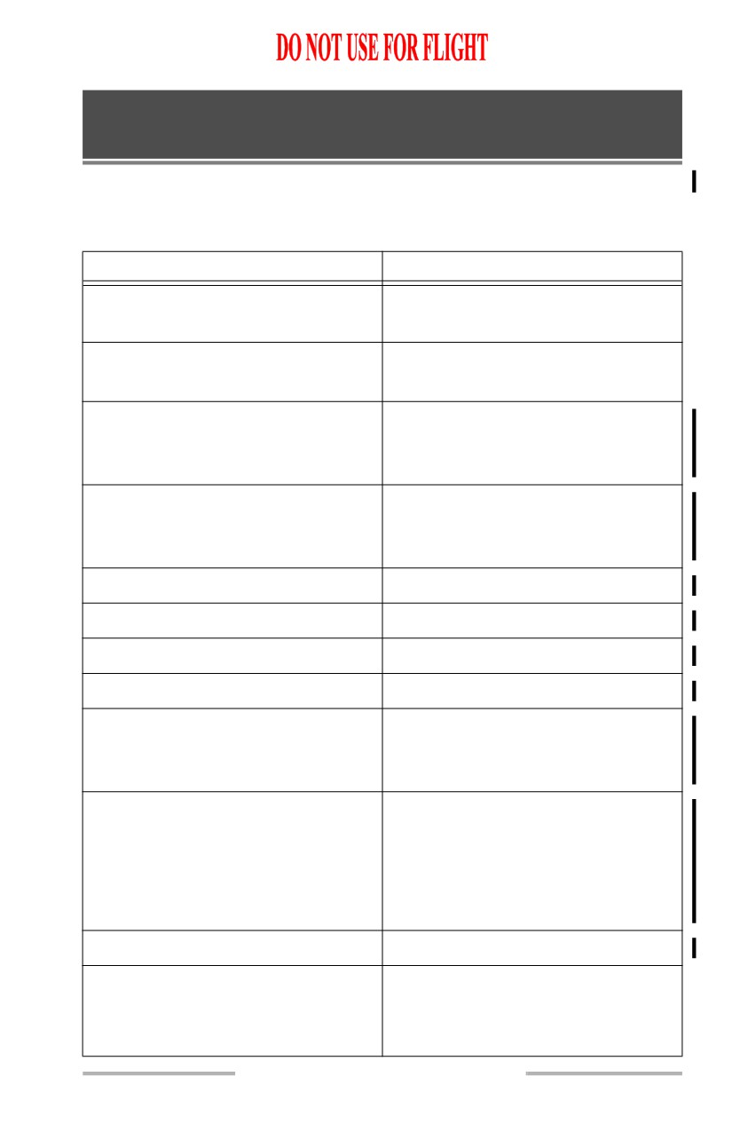
This is a check of normal flight control functions and is not a complete check of
the flight control system. Two people are required; both on interphone.
FLIGHT DECK ACTION
GROUND RESPONSE
Electrical power (APU or external)
- On bus
System A and B electric hydraulic
pump switches - OFF
Control wheel - Left
“LEFT AILERON UP, TAB
DOWN; RIGHT AILERON
DOWN, TAB UP”
Control wheel - Right
“LEFT AILERON DOWN, TAB
UP; RIGHT AILERON UP, TAB
DOWN”
Control wheel - Neutral
Control column - Forward
“ELEVATOR DOWN, TABS UP”
Control column - Aft
“ELEVATOR UP, TABS DOWN”
Control column - Neutral
Request hydraulic clearance
“CLEAR FOR HYDRAULIC
PRESSURE, WING AND
CONTROL AREAS CLEAR”
System A and B electric hydraulic
pump switches - ON
Verify System A & B pressure
indicators and brake pressure
indicator read 2800 psi minimum
Parking brake - Set
Rudder trim - Turn left
Verify left rudder pedals move
forward
SP.9.1

Supplementary Procedures -
Flight Controls
Boeing 737 Operations Manual
FLIGHT DECK ACTION
GROUND RESPONSE
Rudder trim - Turn right
Verify right rudder pedals move
forward
Rudder trim
- Zero, pedals
centered
Aileron trim - Turn left
Verify control wheel turns to left
Aileron trim - Turn right
Verify control wheel turns to right
Aileron trim - Zero, control wheels
centered
Flap lever - UP
Verify flap position indicator reads
zero
Nose gear steering wheel - Hold
“LEFT
AILERON
UP,
TAB
DOWN; LEFT
FLIGHT
Control wheel - Left
SPOILERS
UP;
RIGHT
Control column - Forward
AILERON DOWN,
TAB UP;
Rudder pedal - Left
RUDDER LEFT; ELEVATORS
DOWN, TABS UP”
Nose gear steering wheel - Hold
“LEFT AILERON DOWN, TAB
UP; RIGHT FLIGHT SPOILERS
Control wheel - Right
UP; RIGHT AILERON UP, TAB
Control column - Aft
DOWN; RUDDER RIGHT;
Rudder pedal - Right
ELEVATORS UP, TABS DOWN”
Flight controls - Neutral
Alternate flaps master switch
-
ARM
Flap lever - Position 1
Verify no flap movement
SP.9.2

Supplementary Procedures -
Flight Controls
Boeing 737 Operations Manual
FLIGHT DECK ACTION
GROUND RESPONSE
Alternate flaps position switch -
“FLAPS MOVING DOWN”
hold DOWN until flap position
indicator indicates 1
Flap position indicator - flaps 1
“ALL
LEADING
EDGE
DEVICES FULLY EXTENDED”
Verify aft overhead leading edge
devices annunciator panel indicates
all green (FULL EXTEND) with
no amber lights illuminated.
Verify LE FLAPS TRANSIT light
remains illuminated
Alternate flaps master switch
-
“LEADING EDGE FLAPS
OFF
FULLY EXTENDED, ALL
LEADING EDGE SLATS
Verify Aft overhead leading edge
RETRACTED TO EXTEND
devices annunciator panel indicates
POSITION”
all leading edge flaps full extended
and all leading edge slats in extend
position
Verify LE FLAPS EXT light
illuminated
Speed brake lever - UP
“ALL SPOILERS UP”
Speed brake lever - DOWN
“ALL SPOILERS DOWN”
Stabilizer trim switches - NOSE
“STABILIZER LEADING EDGE
DOWN
MOVING UP”
Stabilizer trim switches - NOSE
“STABILIZER LEADING EDGE
UP
MOVING DOWN”
With stabilizer still moving:
Stabilizer trim cutout switches
-
CUTOUT
Verify trim motor stops
SP.9.3
Supplementary Procedures -
Flight Controls
Boeing 737 Operations Manual
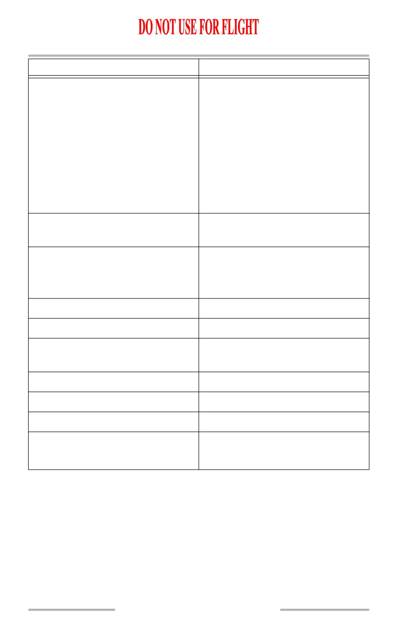
FLIGHT DECK ACTION
GROUND RESPONSE
Stabilizer trim cutout switches
-
NORMAL
Verify Trim motor resumes
Control column - Forward
Verify Trim motor stops
Column actuated stab trim override
- OVERRIDE
Verify Trim motor resumes
Stabilizer trim switches - Trim into
green band
Column actuated stab trim override
- NORMAL
Switch guard - Close
Request clearance to flaps 30
“FLAPS CLEAR”
Flap lever - Position 30
“FLAPS MOVING DOWN”
Control column - Forward
“ELEVATOR DOWN, TABS
DOWN”
Control column - Aft
“ELEVATOR UP, TABS UP”
Control column - Neutral
Flap lever - UP
“FLAPS MOVING UP”
Parking Brake - As desired
Electrical power - As desired
SP.9.4
Boeing 737 Operations Manual
Supplementary Procedures
Chapter SP
Flight Instruments, Displays
Section 10
Altimeter Difference
Note: If flight in RVSM airspace is planned use the RVSM table in the
limitations section.
This procedure is accomplished when there is a noticeable difference between the
altimeters. Accomplish this procedure in stabilized level flight or on the ground.
Altimeter barometric settings
Check
Check all altimeters set to proper barometric setting for phase of flight.
Standby altimeter baro set control
Rotate and reset
Rotate to a different setting, then reset proper barometric setting.
Altimeters
Crosscheck
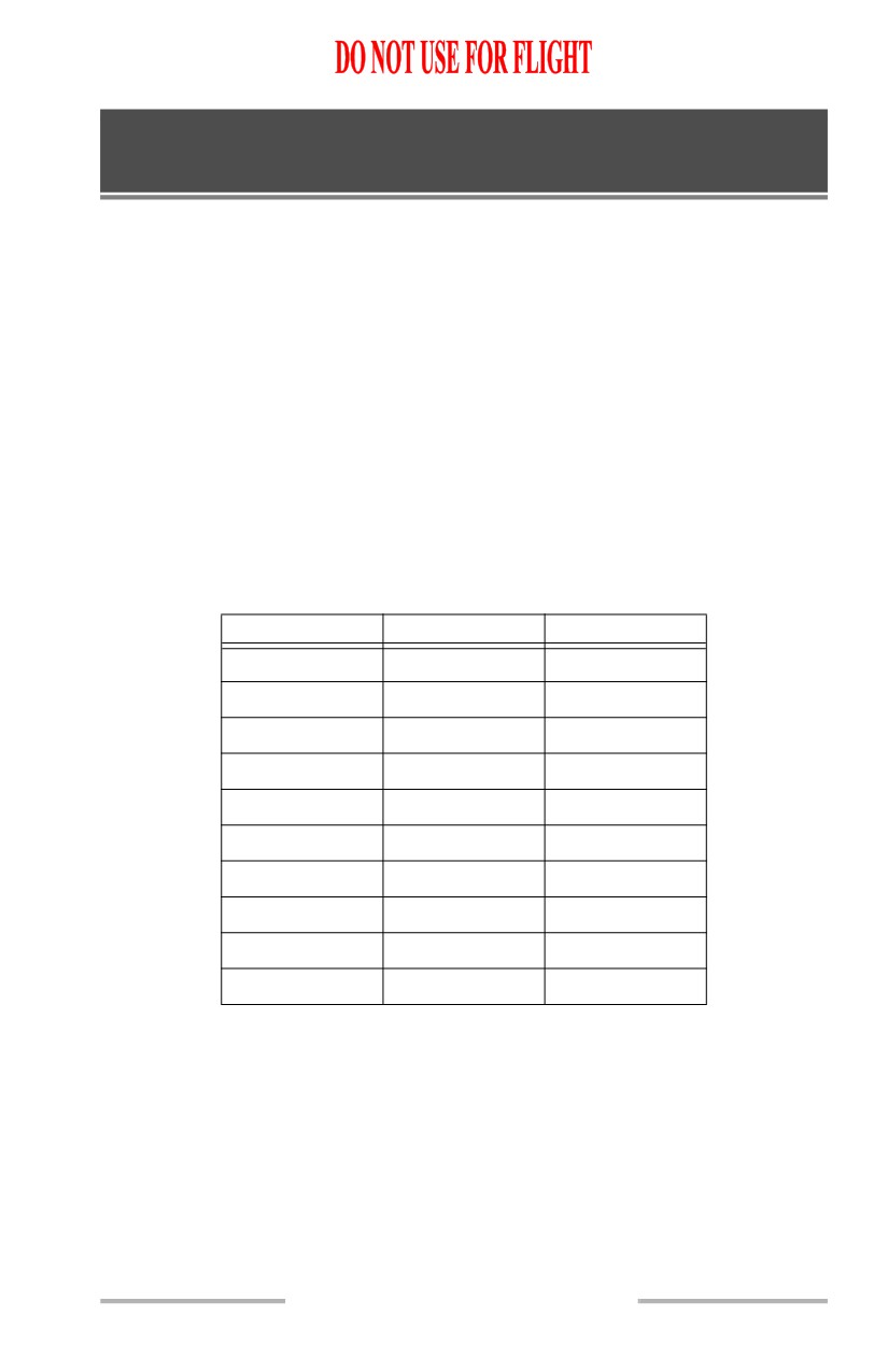
Maximum differences between the altimeter readings:
Altitude
CDS/CDS
CDS/Standby
Sea Level
50 feet
50 feet
5,000 feet
50 feet
80 feet
10,000 feet
60 feet
120 feet
15,000 feet
70 feet
(see note)
20,000 feet
80 feet
(see note)
25,000 feet
100 feet
(see note)
30,000 feet
120 feet
(see note)
35,000 feet
140 feet
(see note)
40,000 feet
160 feet
(see note)
41,000 feet
170 feet
(see note)
Note: Above 10,000 feet and 0.4 Mach, position error causes the
tolerance to diverge rapidly and direct crosscheck becomes
inconclusive. Differences greater than 400 feet should be
suspect and verified by ground maintenance checks.
If it is not possible to identify which altimeter is indicating the correct
altitude:
ATC
Notify
SP.10.1
Supplementary Procedures -
Flight Instruments, Displays
Boeing 737 Operations Manual
QFE Operation
This procedure is accomplished when ATC altitude assignments are referenced to
QFE altimeter settings.
Note: Do not use LNAV or VNAV below transition altitude/level.
Altitudes in the navigation data base are not referenced to QFE.
Use only raw data for navigation.
[Option - Altimeter with QFE]
FMC/CDU APPROACH REFERENCE page
or TAKEOFF REFERENCE page 2/2
Select
LANDING REF line select key
Push
Verify QFE selected.
[This sets the landing altitude to zero.]
Altimeters
Set
Set altimeters to QFE when below transition altitude/level.
Note: If QFE altimeter setting is beyond the range of the altimeters,
QNH procedures must be used with QNH set in the altimeters.
Landing altitude indicator
Set at zero
SP.10.2
October 15, 2001
Supplementary Procedures -
Flight Instruments, Displays
Boeing 737 Operations Manual
Setting Airspeed Bugs with an Inoperative FMC
To set reference airspeed bugs for takeoff:
Speed reference selector (outer)
V1
Default speed of 80 knots is displayed.
Speed reference selector (inner)
Set V1 speed
V1 bug is displayed when a speed greater than 80 knots is set. The NO
VSPD flag is displayed until both V1 and VR are set.
Speed reference selector (outer)
VR
Default speed of 80 knots is displayed.
Speed reference selector (inner)
Set VR speed
VR bug is displayed when a speed greater than 80 knots is set. The NO
VSPD flag is removed after both V1 and VR are set.
MCP speed selector
Set V2
Airspeed cursor and V2+15 bug move to the correct speeds.
Speed reference selector (outer)
WT
Default weight of 32,000 kgs / 70,000 lbs is displayed.
Speed reference selector (inner)
Set takeoff gross weight
Flaps up maneuver speed bug is displayed.
Note: If VREF is selected on the ground, INVALID ENTRY is
displayed.
To set the spare bug, if desired:
Speed Reference selector (outer)
Spare bug
Default speed of 60 knots is displayed.
Speed reference selector (inner)
Set
Set speed as desired.
Speed reference selector (outer)
SET
Digital readout is removed.
Note: When the flap lever is set to any takeoff flap setting above
flaps 1, a bug comes into view for the next smaller flap
maneuvering speed, between takeoff flaps and flaps up. For
SP.10.3