Boeing 737 - 600/700/800/900. Operations Manual (1997 year) - page 9
Normal Procedures -
Amplified Procedures
Boeing 737 Operations Manual
Final Flight Deck Preparation - Captain and First Officer
[Option - EFIS/MAP]
N1 & IAS bugs
Set
Verify N1 reference bugs reflect the full rated N1 value or the derated
N1 value if a TAKEOFF DERATE is selected. Set V2 in the MCP
IAS/Mach display and check airspeed cursors. Check speed bugs at
V1, VR, V2 + 15, and flaps up maneuvering speed.
[Option - PFD/ND]
N1 & IAS bugs
Set
Verify N1 reference bugs reflect the full rated N1 value or the derated
N1 value if a TAKEOFF DERATE is selected. Set V2 in the MCP
IAS/Mach display. Verify V1 speed is displayed at the top of airspeed
indication.
Engine start clearance
Obtain
The captain calls “BEFORE START CHECKLIST DOWN TO THE
LINE.”
The first officer accomplishes the BEFORE START checklist, down to
the line.
- - - - - - - - - - - - CLEARED FOR START - - - - - - - - - - - -
Doors
Closed
All exterior door annunciator lights - Extinguished
Flight deck windows
Locked
Verify the lock levers are in the locked (forward) position.
Air conditioning PACK switches
OFF
ANTI COLLISION light switch
ON
Alerts the ground crew and tower that the flight crew is starting
engines.
The captain calls “BEFORE START CHECKLIST BELOW THE
LINE.”
The first officer completes the BEFORE START checklist.
NP.20.24

Normal Procedures -
Amplified Procedures
Boeing 737 Operations Manual
Engine Start Procedure
CAPTAIN
FIRST OFFICER
Announce engine start sequence.
Normal starting sequence is 2, 1.
Call “STARTING ENGINE No. ___.”
Position ENGINE START switch to
GRD.
Verify increase in N2 RPM.
Acknowledge first officer’s report.
Verify increase in oil pressure by the
time engine is stabilized at idle and call
“OIL PRESSURE RISING” when
observed.
Position engine start lever to IDLE
detent when:
• N1 rotation is observed and
• N2 RPM reaches 25% or
(if 25% N2 is not achievable)
• at max motoring and a
minimum of 20% N2.
Max motoring occurs when
N2 acceleration is less than
1% in approximately
5
seconds.
Verify fuel flow and EGT indication.
[Without automatic ignition]
[Without automatic ignition]
At 56% N2 RPM check ENGINE
Verify START VALVE OPEN alert
START switch moves to OFF; if not,
extinguishes as the ENGINE START
position start switch to OFF.
switch moves to OFF and report
“STARTER CUTOUT.”
[Automatic ignition]
At 56% N2 RPM check ENGINE
[Automatic ignition]
START switch moves to AUTO; if not,
Verify START VALVE OPEN alert
position start switch to AUTO.
extinguishes as the ENGINE START
switch moves to AUTO and report
“STARTER CUTOUT.”
Monitor N1, N2, EGT, fuel flow and oil pressure for normal indications as the
engine accelerates and stabilizes at idle.
NP.20.25
Normal Procedures -
Amplified Procedures
Boeing 737 Operations Manual
Note: Standard day, sea level, approximate stabilized idle indications
for the CFM56-7 engine.
• N1 RPM - 20%
• EGT - 410°C**
• N2 RPM - 59%
• Fuel Flow - 272 KGPH/600 PPH
** Idle EGT may vary from 320°C - 520°C depending on OAT, bleed
configuration, and engine conditions.
Starter Duty Cycle
• Limit each start attempt to a maximum of 2 minutes
• A minimum of 10 seconds is required between start attempts
CAUTION: Normal engine start considerations:
• Advancing engine start lever to idle prematurely can cause a “HOT” start.
• Keep hand on engine start lever while observing RPM, EGT and fuel flow
until stabilized.
• If fuel is shutoff inadvertently (by closing engine start lever) do not
reopen engine start lever in an attempt to restart engine.
• Failure of ENGINE START switch to hold in GRD until starter cutout
RPM is reached can result in a “HOT” start. Do not re-engage ENGINE
START switch until engine RPM is below 20% N2.
Note: Accomplish the ABORTED ENGINE START checklist for one
or more of the following conditions:
• No N1 rotation before the engine start lever is raised to IDLE.
• No oil pressure indication by the time the engine is stabilized at idle.
• No increase in EGT within 10 seconds of raising the engine start lever to
IDLE.
• No increase in, or a very slow increase in N1 or N2 after EGT indication.
• EGT rapidly approaching or exceeding the start limit.
NP.20.26
Normal Procedures -
Amplified Procedures
Boeing 737 Operations Manual
After Start Procedure
Electrical
Generators ON
Both GENERATOR switches - ON
GEN OFF BUS lights - Extinguished
SOURCE OFF lights - Extinguished
PROBE HEAT switches
ON
All probe heat lights - Extinguished
Anti-Ice
As required
Air conditioning and pressurization
Set
Pack switches - AUTO
APU BLEED air switch - OFF
ISOLATION VALVE switch
AUTO
APU
As required
Start levers
IDLE detent
Ground equipment
Removed
Seat belts and shoulder harnesses
Fastened
The captain calls “AFTER START CHECKLIST.”
The first officer accomplishes the AFTER START checklist.
NP.20.27
Normal Procedures -
Amplified Procedures
Boeing 737 Operations Manual
Pushback or Tow Out Procedure
This procedure is required when the airplane is to be pushed back or towed away
from the terminal or loading area.
WARNING: Prior to installing the nose gear steering lockout pin,
do not make any electrical or hydraulic power
changes with tow bar connected. Any change to
electrical power may cause momentary
pressurization of the nose wheel steering actuators
causing unwanted tow bar movement.
Flight interphone contact with ground crew
Establish
Nose gear steering lockout pin
Installed
System A HYDRAULIC PUMPS switches
ON/OFF
If the nose gear steering lockout pin is installed, pushback or tow out
may be accomplished with system A pressurized or depressurized.
CAUTION: If the nose gear steering lockout pin is not installed,
system A HYDRAULIC PUMPS must be placed off.
When cleared for pushback or tow out:
Brakes
Off
When airplane is stopped:
Brakes
On
Parking brake
Set
Tow bar
Disconnected
Clearance from ground crew
Clear
Nose gear steering lockout pin
Removed
System A HYDRAULIC PUMPS switches
ON
Interphone
Removed
NP.20.28
Normal Procedures -
Amplified Procedures
Boeing 737 Operations Manual
Before Takeoff Procedure
Recall
Check
Flight controls
Check
Displace rudder pedals, control wheel and control column in both
directions. Verify full travel, freedom of movement and controls
return to center. Hold nose wheel steering wheel during rudder check
to prevent nose wheel movement.
Flaps
______, Green light
Flap position indicator and FLAP lever - Set for takeoff
LEADING EDGE FLAPS EXTENDED green light - Illuminated
Stabilizer trim
______units
Verify stabilizer trim is set for takeoff.
Cabin door
Lock
CABIN DOOR UNLOCKED light - Extinguished
Takeoff briefing
Review
The pilot taxiing calls “BEFORE TAKEOFF CHECKLIST DOWN TO
THE LINE.”
The pilot not taxiing accomplishes the BEFORE TAKEOFF checklist
down to the line.
- - - - - - - - - - - CLEARED FOR TAKEOFF - - - - - - - - - - -
[Without automatic ignition]
ENGINE START switches
CONT
LANDING lights and STROBE light switches
As desired
ON unless weather conditions make it undesirable.
Autothrottle
ARM
When approaching the takeoff runway, arm the autothrottle.
FMC position update
As desired
NP.20.29
Normal Procedures -
Amplified Procedures
Boeing 737 Operations Manual
[Option - Runway position update with TO/GA activation]
Enter runway offset on TAKEOFF REF page of FMC/CDU.
[Option - Runway position update with the CDU only]
Update to runway threshold on the TAKEOFF REF page of
FMC/CDU.
Transponder
ON
The pilot taxiing calls “BEFORE TAKEOFF CHECKLIST BELOW
THE LINE.”
The pilot not taxiing completes the BEFORE TAKEOFF checklist.
NP.20.30

Normal Procedures -
Amplified Procedures
Boeing 737 Operations Manual
Takeoff Procedure
PILOT FLYING
PILOT NOT FLYING
Advance thrust
levers
to
approximately 40% N1.
Observe engine instruments stabilized and normal.
Push either TO/GA switch to
advance the thrust levers to takeoff
N1.
Verify mode annunciation.
Ensure thrust levers advance to
takeoff
N1. Observe mode
annunciation.
Note: In cases of extreme
headwind, the thrust
levers may not advance
to full N1. In this case,
manually advance the
thrust levers as required.
Note: After takeoff thrust is set, the captain’s hand must be on the
thrust levers until V1.
Hold light forward pressure on the
Monitor engine instruments. Verify
control
column,
maintain
oil pressure is not in the amber
directional control.
band.
Verify 80 knots.
Call “80 KNOTS.”
Verify that A/T annunciation
changes to THR HLD by 84 knots.
Monitor airspeed, noting V1, and
[Automatic V1 callout]
rotate smoothly at VR.
Confirm automatic V1 callout or
call “V1”.
At VR call “ROTATE”.
Monitor flight instruments.
When a positive rate of climb is
Verify positive rate of climb.
indicated, call
“GEAR UP” and
Position landing gear lever UP.
continue rotation to takeoff pitch
attitude.
Check flight instrument indications.
NP.20.31

Normal Procedures -
Amplified Procedures
Boeing 737 Operations Manual
After Takeoff Procedure
PILOT FLYING
PILOT NOT FLYING
Maintain a minimum of V2 + 15
Monitor engine instruments and
knots during initial climb. At light
cross-check flight progress.
gross weight a higher speed (up to
V2 + 25) may be selected, to
synchronize F/D pitch command
and avoid objectionable body
attitude.
Above 400 feet, call for appropriate
Select/verify roll mode. Verify
roll mode, if required. Verify proper
proper mode annunciation.
mode annunciation.
[Without auto T/O thrust
[Without auto T/O thrust
reduction]
reduction]
Above 1,000 feet, call for N1 and
Select N1 and set
flaps up
flaps up maneuvering speed. Verify
maneuvering speed.
flight
and
thrust
mode
[Auto T/O thrust reduction]
annunciations.
Set flaps up maneuvering speed.
[Auto T/O thrust reduction]
Verify climb thrust is set.
Above 1,000 feet, call for flaps up
Verify proper mode annunciation.
maneuvering speed. Verify flight
and thrust mode annunciations at
thrust reduction altitude.
When above minimum altitude for
Verify autopilot engaged.
autopilot engagement, engage A/P.
Verify flight mode annunciation.
Retract flaps on takeoff flap
Position FLAP lever as directed and
retraction speed schedule.
monitor flaps and slats retraction.
Call
“AFTER
TAKEOFF
Position landing gear lever OFF,
CHECKLIST” when flaps are up.
APU and engine start switches as
required. Verify air conditioning
and
pressurization
operating
normally. Accomplish the AFTER
TAKEOFF checklist.
Above 3,000 feet AGL, engage
Verify proper mode annunciation.
VNAV or select normal climb speed
and verify annunciation.
NP.20.32

Normal Procedures -
Amplified Procedures
Boeing 737 Operations Manual
CAUTION: To avoid the possibility of shoulder harness buckles
snapping back and pulling or damaging circuit
breakers, hold both straps before releasing and then
allow straps to retract slowly to the stowed position.
Takeoff Flap Retraction Speed Schedule
T/O
SELECT
AT:
FLAPS
FLAPS
(for all weights)
25
15
V2 + 15
5
“15”
1
“5”
UP
“1”
15
5
V2 + 15
1
“5”
UP
“1”
10
5
V2 + 15
1
“5”
UP
“1”
5
1
V2 + 15
UP
“1”
1
UP
“1”
•
“UP” - Flaps up maneuvering speed.
•
“1”, “5”, “10”, “15”. “25” - Number corresponding
to flap maneuvering speed.
Note: Limit bank angle to 15 degrees until reaching V2 + 15.
NP.20.33

Normal Procedures -
Amplified Procedures
Boeing 737 Operations Manual
Climb and Cruise Procedure
PILOT FLYING
PILOT NOT FLYING
Position landing lights OFF passing
through 10,000 feet.
Set altimeters to standard at transition altitude.
Approaching selected FMC cruise altitude, verify level off and proper
mode/N1 limit annunciation.
Position center tank fuel pump
switches OFF when both pump
LOW PRESSURE lights
illuminate.
During the last hour of cruise on all
extended range (more than one hour
from an adequate airport) flights,
perform Fuel Crossfeed Valve
check.
Set MCP altitude selector for
Prior to top of descent, select and
descent.
verify the planned arrival procedure
on the FMC.
At top of descent point observe descent initiated and verify proper mode
annunciation.
Note: If a center tank LOW PRESSURE light(s) illuminates during
takeoff or initial climb, the center tank pump(s) may remain on
until the climb attitude is reduced and the light(s) extinguishes
or workload allows for the pump(s) to be positioned OFF.
Note: When established in a level attitude at cruise, if the center tank
contains usable fuel and the center tank pump switches are off,
the center tank pump switches should be positioned ON again.
If the center tank contains more than 1000 lbs/453 kgs, the
center tank pump switches must be positioned ON. Verify the
LOW PRESSURE lights extinguish and position both switches
OFF when both LOW PRESSURE lights illuminate.
NP.20.34
Normal Procedures -
Amplified Procedures
Boeing 737 Operations Manual
Descent and Approach Procedure
PILOT FLYING
PILOT NOT FLYING
Position center tank fuel pump
switches OFF when both pump
LOW PRESSURE lights
illuminate.
Check and set VREF and approach speeds as required.
Set anti-ice as required.
Verify pressurization set for
destination airport elevation and
system operating normally.
Set AUTO BRAKE select switch to desired brake setting.
Set and crosscheck altimeters at transition level.
Set and crosscheck course selection and RADIO/BARO minimums as
required for approach.
Set and verify ADF and VHF NAV radios for approach.
Position fixed landing lights ON
passing through 10,000 feet.
Call
“DESCENT-APPROACH
Accomplish the DESCENT-
CHECKLIST.”
APPROACH checklist.
Call “FLAPS __” according to flap
Position FLAP lever as directed and
speed schedule.
monitor flap and slat extension.
Accomplish standard callouts.
Approaching selected FMC altitude verify level off and mode
annunciation.
Note: If a center tank LOW PRESSURE light(s) illuminate(s) during
descent, position the center tank fuel pump switch(es) to OFF.
Note: When established in a level attitude, if the center tank contains
usable fuel and the center tank pump switches are off, the center
tank pump switches should be positioned ON again. If the
center tank contains more than 1000 lbs/453 kgs, the center tank
pump switches must be positioned ON. Verify the LOW
PRESSURE lights extinguish and position both switches OFF
when both LOW PRESSURE lights illuminate.
NP.20.35
Normal Procedures -
Amplified Procedures
Boeing 737 Operations Manual
Approach Procedure
Using flaps as speed brakes is not recommended.
The following procedures are used for flap extension:
• Select flaps 1 when decelerating through the flaps-up maneuvering
speed, displayed on the airspeed display as a “UP”.
• Set airspeed cursor to the flap maneuvering speed displayed as “1”.
• When appropriate, select the next flap position and then set the
airspeed cursor to that flap maneuver speed.
Note: Flap maneuver speeds provide approximately 15 to 20 knots
above the minimum maneuvering speed for each flap setting.
Note: If performance requires the use of flaps 15 for landing, place the
GROUND PROXIMITY flap inhibit switch to FLAP INHIBIT.
If the flap maneuvering speeds cannot be displayed, reference the Performance
In-flight section for speed schedules.
When on final approach in landing configuration, it is not recommended to set the
A/T command speed to allow for wind or gust corrections. Through airspeed and
acceleration sensing, the A/T corrects for normal wind gusts. Higher command
speed settings result in excessive approach speeds. The recommended A/T
approach speed setting is VREF + 5.
NP.20.36

Normal Procedures -
Amplified Procedures
Boeing 737 Operations Manual
Landing Procedure
PILOT FLYING
PILOT NOT FLYING
When on localizer intercept
Set transponder mode selector to
heading, verify ILS tuned and
desired TCAS mode.
identified, LOC and G/S pointer
displayed, arm APP mode and
engage second autopilot.
Verify mode annunciation.
At localizer capture verify proper
Verify proper mode annunciation.
mode annunciation and set
appropriate heading.
At glide slope “alive”, call “GEAR
[Without automatic ignition]
DOWN”, “FLAPS 15." Arm speed
Position landing gear lever DN,
brake and check green light
FLAP lever to the
15 detent.
illuminated. Call
“LANDING
Position engine start switches to
CHECKLIST DOWN TO FLAPS.”
CONT. Check RECALL.
[Automatic ignition]
Position landing gear lever DN,
FLAP lever to the 15 detent. Check
RECALL.
Accomplish
the
LANDING
checklist down to flaps. State
“HOLDING AT FLAPS.”
At glide slope capture, verify proper mode annunciation, check N1
reference bug at the go-around limit and set missed approach altitude.
Call “FLAPS ____” as required for
Position FLAP lever as directed.
landing. Set MCP speed selector at
VREF + 5 knots.
At final approach fix/OM, verify crossing altitude.
Call
“COMPLETE
THE
Complete the LANDING checklist.
LANDING CHECKLIST.”
Monitor approach progress and guard the controls.
At 500 feet AGL, verify FLARE is armed.
At approximately 50 feet AGL, verify FLARE is engaged.
Ensure the autothrottle retards the thrust levers to idle by touchdown.
NP.20.37
Normal Procedures -
Amplified Procedures
Boeing 737 Operations Manual
Go-Around Procedure
PILOT FLYING
PILOT NOT FLYING
Push TO/GA switch.
Monitor N1 indication. Position
FLAP lever to 15 and monitor flap
Call “FLAPS 15.”
retraction.
If full GA thrust is required, push
TO/GA switch again after reduced
GA thrust is established.
Confirm rotation to go-around
attitude and monitor autopilot.
Verify mode annunciation.
When positive rate of climb is
Verify positive rate of climb.
indicated, call
“GEAR UP” and
Position landing gear lever UP.
monitor acceleration.
Check flight instrument indications (MCP speed window blanks).
Call
“TUNE RADIOS FOR
Tune radios as directed.
MISSED APPROACH.”
Above 400 feet, select appropriate
Observe mode annunciation.
roll mode and verify proper mode
annunciation.
Retract flaps on flap speed
Position FLAP lever as directed and
schedule.
monitor flaps and slats retraction.
Verify airplane levels off at selected altitude and maintains flap
maneuvering speed.
Call
“AFTER
TAKEOFF
Accomplish
the
AFTER
CHECKLIST.”
TAKEOFF checklist.
NP.20.38
Normal Procedures -
Amplified Procedures
Boeing 737 Operations Manual
Landing Roll Procedure
PILOT FLYING
PILOT NOT FLYING
Ensure thrust levers at idle.
Disengage autopilot and control
Verify autothrottle is disengaged.
airplane manually.
Verify autothrottle disengages
automatically.
Verify SPEED BRAKE lever
Verify SPEED BRAKE lever UP.
(ground spoilers) - UP.
Call out “SPEED BRAKES UP.”
If SPEED BRAKE lever not UP,
call “SPEED BRAKES NOT UP.”
Verify proper autobrake operation.
Without delay, raise reverse thrust
Monitor engine instruments and
levers to the interlocks, hold light
announce any engine limit being
pressure until release, and then
approached, exceeded or any other
apply reverse thrust as required.
abnormalities.
At 60 knots, reduce reverse thrust to
Call “60 KNOTS”
be at IDLE reverse when reaching
taxi speed.
Approaching taxi speed, slowly
Verify
REV
indication
move the reverse thrust levers to the
extinguished.
full down position.
Prior to taxi speed, disarm the
autobrake and continue manual
braking as required.
WARNING: After reverse thrust has been initiated, a full stop
landing must be made.
NP.20.39
Normal Procedures -
Amplified Procedures
Boeing 737 Operations Manual
Taxi In Procedure
When clear of the active runway, the pilot taxiing positions the SPEED BRAKE
lever to the DOWN detent and the pilot not taxiing accomplishes the following:
SPEED BRAKE lever
Verify DOWN
FLAP lever
UP
APU (if required)
START
PROBE HEAT switches
OFF
[Without automatic ignition]
ENGINE START switches
OFF
LANDING/TAXI light and STROBE light switches
As desired
FLIGHT DIRECTOR switches
OFF
WEATHER RADAR
Off
Transponder
As desired
APU GENERATOR switches (if APU operating)
ON
CAUTION: To avoid the possibility of shoulder harness buckles
snapping back and pulling or damaging circuit
breakers, hold both straps before releasing and then
allow straps to retract slowly to the stowed position.
NP.20.40
Normal Procedures -
Amplified Procedures
Boeing 737 Operations Manual
Shutdown Procedure
After the airplane has come to a complete stop, perform the following actions:
Parking brake
Set
Parking brake warning light - Illuminated
Electrical
On___
Verify APU powering busses. If APU is not to be used, connect
external power.
Start levers
CUTOFF
If possible, operate the engines at idle for three minutes prior to
shutdown to thermally stabilize the engine hot sections. Operating
times at or near idle, such as taxiing before shutdown, are applicable
to this three-minute period. If operational requirements dictate, the
engines may be shut down with a one-minute cooling period.
FASTEN BELTS switch
OFF
ANTI COLLISION light switch
OFF
FUEL PUMP switches
OFF
CAUTION: Do not operate the center tank fuel pumps with the
flight deck unattended.
CAB/UTIL power switch
As required
IFE/PASS seat power switch
As required
WINDOW HEAT switches
OFF
WING and ENGINE ANTI-ICE switches
OFF
ELECTRIC HYDRAULIC PUMP switches
OFF
[737-600/700]
RECIRCULATION FAN switch
As desired
[737-800/900]
RECIRCULATION FAN switches
As desired
Air conditioning PACK switches
AUTO
ISOLATION VALVE switch - OPEN
NP.20.41
Normal Procedures -
Amplified Procedures
Boeing 737 Operations Manual
Engine BLEED air switches
ON
APU BLEED air switch
ON
Exterior lights
As required
WEATHER RADAR
OFF
AUTO BRAKE select switch
OFF
Flight deck lights
As desired
SPEED BRAKE lever
DOWN detent
Parking brake
As required
With chocks in place, the parking brake may be released.
Transponder
As required
Cabin door
Unlock
The captain calls “SHUTDOWN CHECKLIST.”
The first officer accomplishes the SHUTDOWN checklist.
Secure Procedure
IRS mode selectors
OFF
EMERGENCY EXIT lights switch
OFF
Air conditioning PACK switches
OFF
APU switch/GROUND POWER switch
OFF
If APU was operating:
Delay approximately 2 minutes after the APU GEN OFF BUS
light extinguishes before placing the BATTERY switch OFF.
BATTERY switch
OFF
The captain calls “SECURE CHECKLIST.”
The first officer accomplishes the SECURE checklist.
NP.20.42
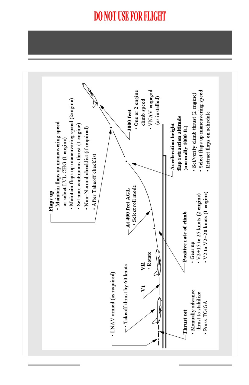
Boeing 737 Operations Manual
Normal Procedures
Chapter NP
Flight Patterns
Section 30
Takeoff
NP.30.1