Boeing 737 - 600/700/800/900. Operations Manual (1997 year) - page 7

Limitations -
Operating Limitations
Boeing 737 Operations Manual
Narrow Runway (30 M) Operation
[Option - 30 Meter Wide Runway]
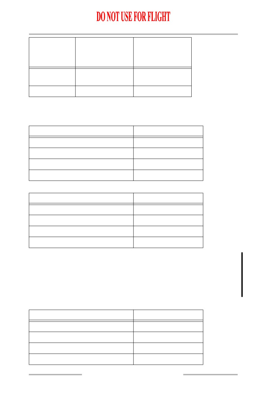
The maximum crosswind component at 10 meter (32.8 feet) height for takeoff and
landing is:
Snow
Model
Dry
Wet
Covered
Flooded
Icy
Runway
Runway
(No Melting)
Runway
Runway
737-600
26 knots
16 knots
12 knots
6 knots
4 knots
737-700
24 knots
13 knots
11 knots
4 knots
*
737-800
27 knots
16 knots
15 knots
10 knots
4 knots
* Operation Not Recommended
Runway centerline shall be clearly visible in the prevailing conditions.
Note: Consult AFM-DPI (Alternate Performance) for adjustment to V1(MCG)
based on 20 foot deviation from runway centerline. An adjustment to
Maximum Takeoff Weight and Takeoff Speeds may also be required.
[Option - 737-600/-700 airplanes with engine performance restrictions]
Note: See AFM Appendix for Aft CG curtailments which may further restrict
airplane takeoff envelope.
Non-AFM Operational Information
Note: The following items are not AFM limitations, but are provided for flight
crew information.
On revenue flights, the escape slide retention bar (girt bar) must be installed
during taxi, takeoff and landing.
[Option - Winglets]
The maximum demonstrated takeoff and landing crosswind is 33 knots.
[Option - No winglets]
The maximum demonstrated takeoff and landing crosswind is 36 knots.
Altitude Display Limits for RVSM Operations
Standby altimeters do not meet altimeter accuracy requirements of RVSM
airspace.
The maximum allowable in-flight difference between Captain and First Officer
altitude displays for RVSM operations is 200 feet.
The maximum allowable on-the-ground altitude display differences for RVSM
operations are:
L.10.2
Limitations -
Operating Limitations
Boeing 737 Operations Manual
Field Elevation
Max Difference
Max Difference
Between
Between
Captain & F/O
Captain or F/O &
Field Elevation
Sea Level to
50 feet
75 feet
5,000 feet
10,000 feet
60 feet
75 feet
Weight Limitations
[Option - Typical 737-600]
Weights
Pounds / Kilograms
Maximum Taxi Weight
127,500 / 57,832
Maximum Takeoff Weight
127,000 / 57,606
Maximum Landing Weight
120,500 / 54,657
Maximum Zero Fuel Weight
114,000 / 51,709
[Option - Typical 737-700]
Weights
Pounds / Kilograms
Maximum Taxi Weight
133,500 / 60,554
Maximum Takeoff Weight
133,000 / 60,327
Maximum Landing Weight
128,000 / 58,059
Maximum Zero Fuel Weight
120,500 / 54,657
[Option - Typical 737-700 with CFM56-7B26 Thrust]
Note: Minimum Takeoff Weight - 125,000 lbs. / 56,699 kgs.
Lower minimum takeoff weights that account for the actual pressure
altitude and outside air temperature may be obtained by using the
Minimum Takeoff Weight table in the Takeoff section of the Performance
Dispatch (PD) chapter.
[Option - Typical 737-800]
Weights
Pounds / Kilograms
Maximum Taxi Weight
156,000 / 70,760
Maximum Takeoff Weight
155,500 / 70,533
Maximum Landing Weight
144,000 / 65,317
Maximum Zero Fuel Weight
136,000 / 61,688
L.10.3

Limitations -
Operating Limitations
Boeing 737 Operations Manual
[Option - Typical 737-900]
Weights
Pounds / Kilograms
Maximum Taxi Weight
174,700 / 79,242
Maximum Takeoff Weight
174,200 / 79,015
Maximum Landing Weight
146,300 / 66,360
144,200 / 65,407
Maximum Landing Weight (Flaps 15 *)
Maximum Zero Fuel Weight
138,300 / 62,731
* This maximum weight applies when landing with Flaps 15 under normal conditions.
It does not apply when Flaps 15 is required during a Non-Normal Checklist.
Air Systems
Pressurization
The maximum cabin differential pressure (relief valves) is 9.1 psi.
Non-AFM Operational Information
With engine bleed air switches ON, do not operate the air conditioning packs in
HIGH for takeoff, approach or landing.
Anti-Ice, Rain
Engine TAI must be on when icing conditions exist or are anticipated, except
during climb and cruise below -40°C SAT.
[Option - 737-600/-700/-800 without stiffened elevator tabs]
(PRR 38506 or Service Bulletin 737-55A1080)
After any ground deicing/anti-icing of the horizontal stabilizer, airspeed must be
limited to 270 KIAS until the crew has been informed that applicable maintenance
procedures have been accomplished that would allow exceedance of 270 KIAS.
Once the applicable maintenance procedures have been accomplished, exceeding
270 KIAS is permissible only until the next deicing/anti-icing.
Autopilot/Flight Director System
Do not engage the autopilot for takeoff below 400 feet AGL.
[Option - High altitude landing system]
Do not use the autopilot below 100 feet radio altitude at airport pressure altitudes
above 8,400 feet.
L.10.4

Limitations -
Operating Limitations
Boeing 737 Operations Manual
[Option - JAA rules]
The autopilot must be disengaged before the airplane descends more than 50 feet
below the minimum descent altitude (MDA) unless it is coupled to an ILS glide
slope and localizer or in the go-around mode.
[Option - Typical, 737-800, JAA rules]
The Minimum Use Height (MUH) for single channel autopilot operation is
defined as 158 feet AGL.
[Option - FAA rules]
For single channel operation, the autopilot shall not be engaged below 50 feet
AGL.
Use of aileron trim with the autopilot engaged is prohibited.
[Option - Typical, FAA rules, 15 kt tailwind]
Maximum allowable wind speeds when landing weather minima are predicated on
autoland operations:
• Headwind 25 knots
• Crosswind 20 knots
• Tailwind 15 knots.
[Option - Typical, JAA rules, Cat II or Cat III]
Maximum allowable wind speeds, when conducting a dual channel
Cat II or Cat III landing predicated on autoland operations, are:
• Headwind 25 knots
• Crosswind 20 knots
• Tailwind:
[Option - Typical 737-900, 10 kt tailwind]
Field Elevation
Flaps 30
Flaps 40
2000 feet or less
10 knots
10 knots
2001 to 4000 feet
10 knots
10 knots
4001 to 6000 feet
5 knots
10 knots
Greater than 6000 feet
0 knots
10 knots
L.10.5

Limitations -
Operating Limitations
Boeing 737 Operations Manual
[Option - Typical 737-900, 15 kt tailwind]
Field Elevation
Flaps 30
Flaps 40
2000 feet or less
15 knots
15 knots
2001 to 4000 feet
10 knots
15 knots
4001 to 6000 feet
5 knots
15 knots
Greater than 6000 feet
0 knots
15 knots
HUD System
[Option - Head-Up Display]
[Option - HUD 2350 with winglets or HUD 4000]
AIII mode approach and landings are not approved.
[Option - HUD 2350, No winglets]
For manual CAT II or CAT IIIA approach and landing, AIII mode must be selected
and the autopilot (A/P) and autothrottle (A/T) must be disengaged prior to 500 feet
above TDZE.
[Option - With polar navigation]
Do not use at latitudes greater than 85 degrees latitude.
Communications
[Option - With VHF-3, ACARS or audio entertainment system, and without Voice
Mode Protection]
Do not use VHF-3 for ATC communications with ACARS operational, or if audio
entertainment system is in use.
Aircraft Communications Addressing and Reporting System
[Option - ACARS]
The ACARS is limited to the transmission and receipt of messages that will not
create an unsafe condition if the message is improperly received, such as the
following conditions:
• the message or parts of the message are delayed or not received,
• the message is delivered to the wrong recipient, or
• the message content may be frequently corrupted.
However, Pre-Departure Clearance, Digital Automatic Terminal
Information Service, Oceanic Clearances, Weight and Balance and
Takeoff Data messages can be transmitted and received over ACARS if
they are verified per approved operational procedures.
L.10.6
Limitations -
Operating Limitations
Boeing 737 Operations Manual
Non-AFM Operational Information
Use the VHF radio connected to the top of fuselage antenna for primary ATC
communications on the ground.
Engines and APU
Engine Limit Display Markings
Maximum and minimum limits are red.
Caution limits are amber.
Engine Ignition
Engine ignition must be on for:
• takeoff
• landing
• operation in heavy rain
• anti-ice operation.
Reverse Thrust
Intentional selection of reverse thrust in flight is prohibited.
APU
[Option - Typical JAA]
APU bleed + electrical load: max alt 10,000 ft.
[Option - Typical FAA]
Inflight - APU bleed + electrical load: max alt 10,000 ft.
[Option - Typical FAA]
Ground only - APU bleed + electrical load: max alt 15,000 ft.
APU bleed: max alt 17,000 ft.
APU electrical load: max alt 41,000 ft.
Non-AFM Operational Information
APU bleed valve must be closed when:
• ground air connected and isolation valve open
• engine no. 1 bleed valve open
• isolation and engine no. 2 bleed valves open.
APU bleed valve may be open during engine start, but avoid engine power above
idle.
Do not start or shut down APU during refueling operations.
L.10.7
Limitations -
Operating Limitations
Boeing 737 Operations Manual
Flight Controls
Max flap extension altitude is 20,000 ft.
Holding in icing conditions with flaps extended is prohibited.
Do not deploy the speedbrakes in flight at radio altitudes less than 1,000 feet.
[Option - 737-600/-700/-800 without stiffened elevator tabs]
(PRR 38506 or Service Bulletin 737-55A1080)
Do not operate the airplane at speeds in excess of 300 KIAS with speedbrakes
extended.
WARNING: Use of speedbrakes at speeds in excess of 320 KIAS could
result in a severe vibration, which, in turn, could cause
extreme damage to the horizontal stabilizer.
In flight, do not extend the SPEED BRAKE lever beyond the FLIGHT DETENT.
Non-AFM Operational Information
Alternate flap duty cycle:
Flap Position
Minutes Off
0 - 15
5
greater than 15
25
Flight Management, Navigation
Air Data Inertial Reference Unit (ADIRU)
ADIRU alignment must not be attempted at latitudes greater than 78 degrees 15
minutes.
QFE Selection
The use of LNAV and VNAV with QFE selected is prohibited.
[Option - Altimeter with QFE]
A QFE altitude reference for the PFDs must be selected in the FMS whenever
QFE is used instead of QNH.
[Option - Altimeter with QFE]
QFE operations are prohibited if the option for QFE altitude reference selection is
not installed in the FMS.
Navigational Equipment
Non-AFM Operational Information
Do not operate weather radar during fueling, near fuel spills or people.
L.10.8
Limitations -
Operating Limitations
Boeing 737 Operations Manual
Look-Ahead Terrain Alerting (GPWS)
Do not use the terrain display for navigation.
Do not use the look-ahead terrain alerting and terrain display functions:
• within 15 nm of takeoff, approach or landing at an airport not contained in
the GPWS terrain database
Note: Refer to Honeywell Document 060-4267-000 for airports contained in the
installed GPWS terrain database.
Fuel System
The use of Wide Cut Fuels per Class B of GE Specification D50TF2,
JP-4 or Jet B, is prohibited.
Maximum tank fuel temperature: 49°C.
Minimum inflight tank fuel temperature: 3°C above the freezing point of the fuel
being used or -43°C, whichever is higher.
Allowable lateral imbalance between main tanks 1 and 2 must be scheduled to be
zero. Random fuel imbalance must not exceed 1000 lbs / 453 kgs for taxi, takeoff,
flight or landing.
Fuel crossfeed valve must be closed for takeoff and landing.
Main tanks 1 and 2 must be full if center tank contains more than 1000 lbs /
453 kgs.
Landing Gear
Operation with assumed temperature reduced takeoff thrust is not permitted with
anti-skid inoperative.
[Option - JAA rules]
Towbarless towing operations are restricted to tow vehicles that are designed and
operated to preclude damage to the airplane steering system or which provide a
reliable and unmistakable warning when damage to the steering system may have
occurred.
Non-AFM Operational Information
Do not apply brakes until after touchdown.
L.10.9
Limitations -
Operating Limitations
Boeing 737 Operations Manual
Intentionally
Blank
L.10.10
Boeing 737 Operations Manual
Normal Procedures
Chapter NP
Table of Contents
Section 0
NP.0 Normal Procedures-Table of Contents
Introduction
NP.10.1
General
NP.10.1
Controls and Indications - Nomenclature
NP.10.1
Normal Procedures
NP.10.1
Autopilot Flight Director System and Flight
Management System Monitoring
NP.10.3
CDU Operation
NP.10.3
Panel Scan Diagram
NP.10.4
Pilot Flying/Taxiing and Pilot Not Flying/Not Taxiing
Areas of Responsibility
NP.10.5
Amplified Procedures
NP.20.1
Exterior Safety Inspection - Captain or First Officer
NP.20.1
Flight Deck Safety Inspection - Captain or First Officer
NP.20.1
Preliminary Flight Deck Preparation - Captain or First
Officer
NP.20.2
Exterior Inspection
NP.20.5
Flight Deck Preparation - Captain or First Officer
NP.20.8
Flight Deck Preparation - Captain
NP.20.9
Flight Deck Preparation - First Officer
NP.20.19
Final Flight Deck Preparation - Captain and First
Officer
NP.20.24
Engine Start Procedure
NP.20.25
After Start Procedure
NP.20.27
Pushback or Tow Out Procedure
NP.20.28
Before Takeoff Procedure
NP.20.29
Takeoff Procedure
NP.20.31
After Takeoff Procedure
NP.20.32
Takeoff Flap Retraction Speed Schedule
NP.20.33
NP.TOC.0.1
Normal Procedures -
Table of Contents
Boeing 737 Operations Manual
Climb and Cruise Procedure
NP.20.34
Descent and Approach Procedure
NP.20.35
Approach Procedure
NP.20.36
Landing Procedure
NP.20.37
Go-Around Procedure
NP.20.38
Landing Roll Procedure
NP.20.39
Taxi In Procedure
NP.20.40
Shutdown Procedure
NP.20.41
Secure Procedure
NP.20.42
Flight Patterns
NP.30.1
Takeoff
NP.30.1
ILS Approach
NP.30.2
Instrument Approach using VNAV
NP.30.3
Instrument Approach using V/S
NP.30.4
Circling Approach
NP.30.5
Visual Traffic Pattern
NP.30.6
NP.TOC.0.2
Boeing 737 Operations Manual
Normal Procedures
Chapter NP
Introduction
Section 10
General
This chapter contains Normal Procedures. The first section incorporates routine
normal procedures and associated flight patterns. The second section incorporates
supplementary procedures that are accomplished as required rather than routinely
performed.
Controls and Indications - Nomenclature
Controls and indications appear in all UPPERCASE type to correspond to the
words on the control panel or display. For example, the following item has
UPPERCASE words to match what is found on the panel:
EQUIPMENT COOLING switches
NORMAL
The word EQUIPMENT is spelled out, even though it is abbreviated on the panel.
The following appears in all lower case because there are no words identifying the
panel name.
Engine display control panel
Set
Normal Procedures
Normal procedures are used by the trained flight crew to ensure airplane condition
is acceptable and that the flight deck is correctly configured for each phase of
flight. These procedures assume all systems are operating normally and automated
features are fully utilized.
Procedures are performed from recall and follow a panel flow. Checklists are used
to verify that critical items affecting safety have been accomplished. These
procedures are designed to minimize crew workload and are consistent with flight
deck technology.
During accomplishment of procedures, it is the crew member’s responsibility to
ensure proper system response. If an improper indication is noted, first verify that
the system controls are properly positioned. Then, if necessary, check the
appropriate circuit breaker(s), and test related system light(s.)
Before engine start, individual system lights are used to verify system status. If an
individual system light is indicating an improper condition prior to engine start,
determine if the condition may affect dispatch and require maintenance action or
compliance with the Minimum Equipment List (MEL.)
NP.10.1
Normal Procedures -
Introduction
Boeing 737 Operations Manual
After engine start, the MASTER CAUTION system, annunciator lights, and alerts
are used as the primary means to alert the crew to a non-normal system condition.
Illumination of the MASTER CAUTION and system annunciator lights requires
accomplishment of the appropriate non-normal procedure. Upon completion of
the procedure and prior to takeoff, the Dispatch Deviations Guide (DDG) or
airline equivalent should be consulted to determine if MEL relief is available.
Flight crew duties are organized in accordance with an area of responsibility
concept. Each crewmember is assigned a flight deck area where the crewmember
initiates actions for required procedures.The panel illustrations in this section
describe each crewmember’s area of responsibility for pre/post flight and phase of
flight.
Pre/post flight duties are apportioned between the captain and first officer, while
phase of flight duties are apportioned between the Pilot Flying (PF) and Pilot Not
Flying (PNF.) A normal scan flow is encouraged; however, certain items may be
handled in the most logical sequence for existing conditions. Actions outside the
crew member’s area of responsibility are initiated at the direction of the captain.
General phase of flight responsibilities are as follows:
Pilot flying (PF):
• flight path and airspeed control
• airplane configuration
• navigation.
Pilot not flying (PNF):
• checklist reading
• communications
• tasks requested by PF
• start levers and fire switches (with PF concurrence.)
Phase of flight duties, beginning with the Takeoff Procedure and ending with
completion of the Landing Roll Procedure, are presented in table form in the
appropriate procedures section.
The first officer, when flying the airplane, performs the duties listed under PF, and
the captain performs those duties listed under PNF.
Note: Although the mode control panel is designated as the PF’s responsibility,
the PNF should operate the controls on the mode control panel at the
direction of the PF when the airplane is being flown manually.
The captain retains final authority for all actions directed and performed.
NP.10.2
Normal Procedures -
Introduction
Boeing 737 Operations Manual
Autopilot Flight Director System and Flight Management
System Monitoring
When the autopilot, flight director, or autothrottles are in use and a mode change
is selected or is scheduled to occur, the annunciation must be verified on the flight
mode annunciation display. Airplane course, vertical path, and speed must always
be monitored.
Similarly, when a thrust mode change is selected or is scheduled to occur, the
annunciation must be verified on the thrust mode display.
In LNAV and VNAV, all airplane course, vertical path, thrust and speed changes
must be verified.
CDU Operation
On the ground, the control display unit (CDU) entries are normally performed by
the first officer and verified by the captain.
In flight, CDU entries are normally accomplished by the pilot not flying and
verified by the pilot flying prior to execution. CDU entries should be
accomplished prior to high workload periods such as departure, arrival, or
holding. During high workload periods, using the autopilot modes such as heading
select, level change, and the altitude and speed intervention features, if available,
may be more efficient than entering complex route modifications into the CDU.
NP.10.3
Normal Procedures -
Introduction
Boeing 737 Operations Manual
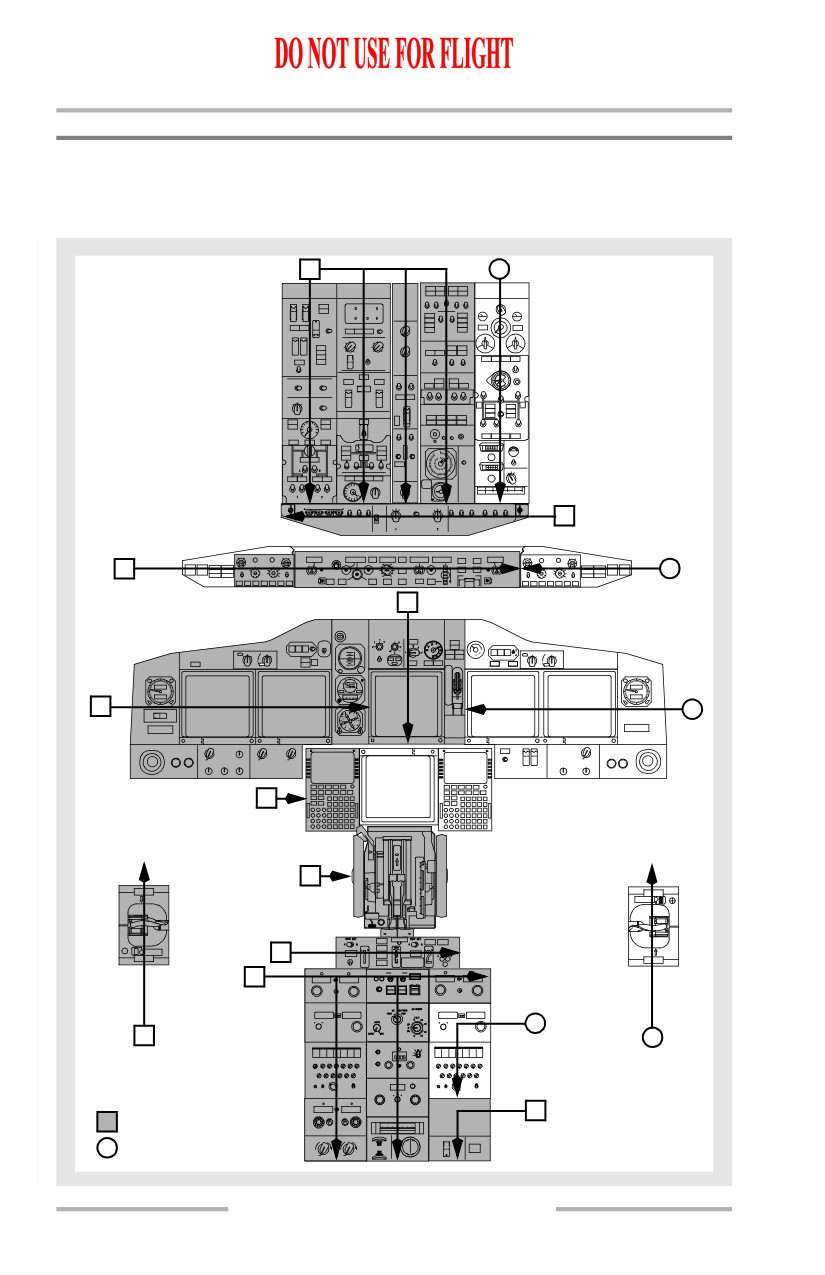
Panel Scan Diagram
The diagram below describes each crew member’s area of responsibility and scan
flow pattern for each panel when the airplane is not moving under its own power.
2
2
1
2
2
165
165
3
3
5
4
0
4
9
6
A/T
2A/T
7
118.00
136.97
C
CA
F
V
118.00
136.97
C
8
VH
O
R
I
R
H
O
F
MM
GO
E
F
MM
N
108.00
108.00
N
108.00
108.00
AV
AV
5
1
1
A
T
T
CA
C
S
H
29.999
C
F
OM
M
AD
8
F
Captain
First Officer
NP.10.4
Normal Procedures -
Introduction
Boeing 737 Operations Manual
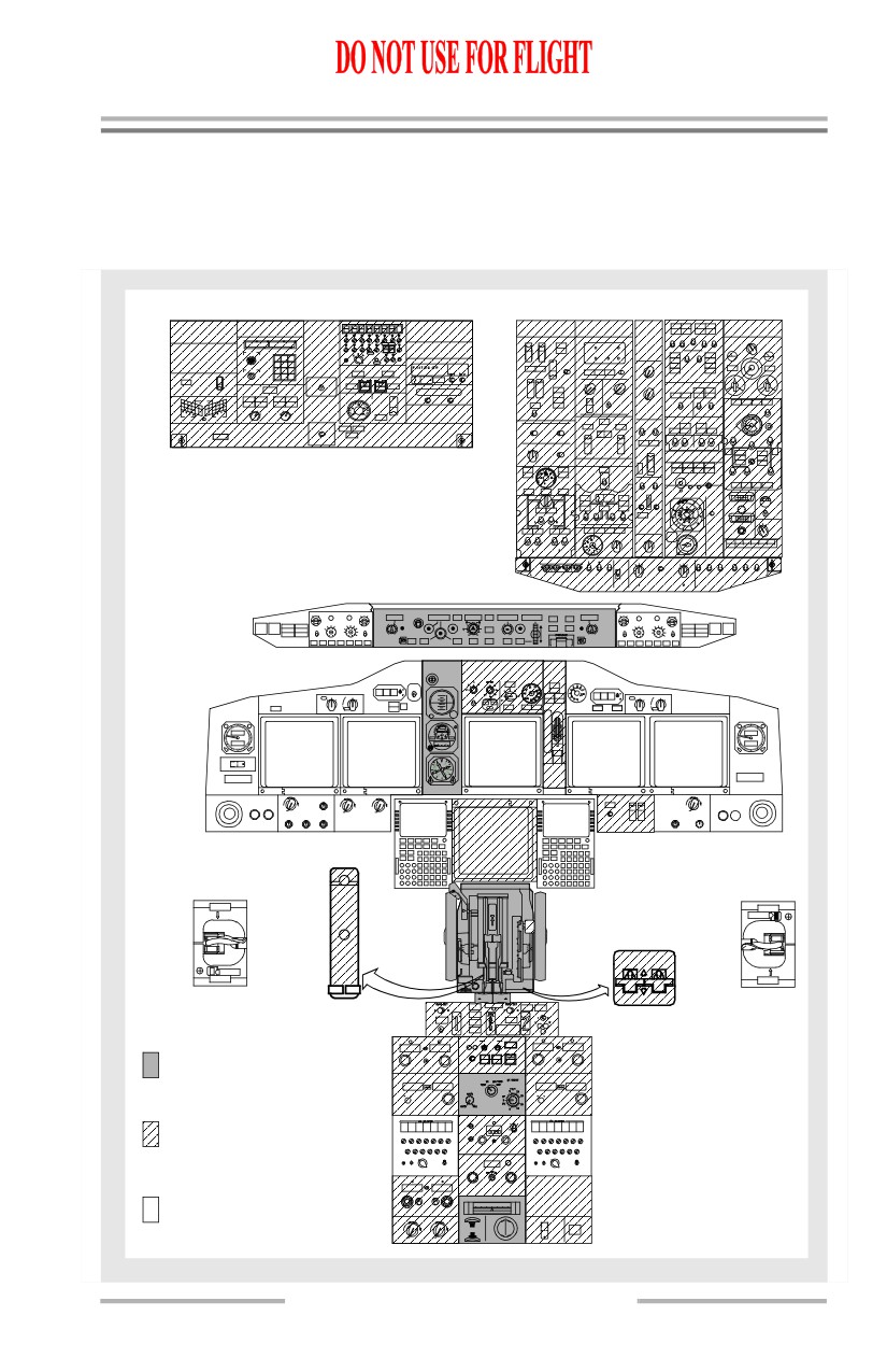
Pilot Flying/Taxiing and Pilot Not Flying/Not Taxiing Areas of
Responsibility
The diagram below describes each crew member’s area of responsibility for each
panel when the airplane is moving under its own power.
N47324
W122123
1
2
ELT
ARM
ELT
ON
GPS
L
R
1
2
PSEU
165
165
0
IDLE
5
05
STAB TRIM
MAINELECT
NORMAL
AUTOPILOT
CUTOFF
1
2
A/T
A/T
2
CUTOUT
V
118.00
136.97
C
CA
I
F
V
118.00
136.97
C
Pilot Flying/Taxiing
H
OM
RG
R
H
OM
F
M
O
E
F
M
(PF) area of
responsibility
N
108.00
108.00
N
108.00
108.00
AV
AV
Pilot Not Flying/Not
AT
T
C
Taxiing (PNF) area
C
S
A
of responsibility
H
29.999
CO
F
MM
Unshaded areas are
A
D
F
the responsibility of
the pilot seated on
the respective side.
NP.10.5
Normal Procedures -
Introduction
Boeing 737 Operations Manual
Intentionally
Blank
NP.10.6
Boeing 737 Operations Manual
Normal Procedures
Chapter NP
Amplified Procedures
Section 20
Exterior Safety Inspection - Captain or First Officer
Surfaces and chocks
Check
Visually check that all movable surfaces are clear and the chocks are
in place.
Maintenance status
Check
Verify maintenance status is acceptable for flight and ensure
agreement with authorized dispatch deviations if required.
Flight Deck Safety Inspection - Captain or First Officer
Perform the following checks prior to assuming normal crew positions.
BATTERY switch
ON
Guard - Down
ELECTRIC HYDRAULIC PUMP switches
OFF
LANDING GEAR lever
DN
All green landing gear indicator lights - Illuminated
NP.20.1
Normal Procedures -
Amplified Procedures
Boeing 737 Operations Manual
Preliminary Flight Deck Preparation - Captain or First Officer
GROUND POWER switch (if ground power is available)
ON
SOURCE OFF lights - Extinguished
Fault/Inop detection
Check
OVERHEAT DETECTOR switches - NORMAL
TEST switch - Hold to FAULT/INOP
Verify MASTER CAUTION, OVHT/DET annunciator, FAULT
and APU DET INOP lights are illuminated.
If the FAULT light fails to illuminate, the fault monitoring system
is inoperative.
If APU DET INOP light fails to illuminate, do not operate APU.
Fire/Overheat warning
Check
Note: Alert ground personnel before this test is accomplished with the
APU operating. The fire warning light flashes and the horn
sounds on the APU ground control panel.
TEST switch - Hold to OVHT/FIRE
Verify fire warning bell sounds, master FIRE WARN lights,
MASTER CAUTION lights and OVHT/DET annunciator
illuminate.
Master FIRE WARNING light - Push
Verify master FIRE WARN lights and fire warning bell cancel.
Verify engine No. 1, APU, and engine No. 2 fire warning switch
and engine No. 1 and engine No. 2 OVERHEAT lights are
illuminated. If AC busses are powered, verify WHEEL WELL fire
warning light is illuminated.
If an engine fire warning switch and an ENG OVERHEAT light
do not illuminate, a detection loop is inoperative.
EXTINGUISHER TEST switch
Check
NP.20.2
Normal Procedures -
Amplified Procedures
Boeing 737 Operations Manual
Position TEST Switch to 1, verify the green extinguisher test lights
are illuminated. Release switch and verify the lights are extinguished.
Repeat for test position 2.
APU
Start & on busses
When the APU GEN OFF BUS light illuminates:
APU GENERATOR bus switches - ON
SOURCE OFF lights - Extinguished
Note: It is recommended that the APU be operated for one minute
before using as a bleed air source.
FLAP lever
Set
Position the FLAP lever to agree with the FLAPS position indicator.
CARGO FIRE system
Check
DETECTOR SELECT switches - NORM
TEST switch - Push
Verify fire warning bell sounds and master FIRE WARN lights
illuminate.
Master FIRE WARN light - Push
Verify master FIRE WARN lights and fire warning bell cancel.
Verify cargo fire (FWD, AFT) warning lights are illuminated.
Verify DETECTOR FAULT light remains extinguished.
Note:If a cargo fire warning light does not illuminate and
the DETECTOR FAULT light illuminates, a detection
loop is inoperative.
Verify the green EXTINGUISHER test lights are illuminated.
Verify the cargo fire bottle DISCHARGE light is illuminated.
Manual gear extension access door
Closed
Emergency equipment
Check
NP.20.3