Haima S5 1.5T. Service Manual - part 4


  Index      Haima     Haima S5 1.5T. Service Manual


Search            copyright infringement  


Content      ..     2      3      4      5     ..


Haima S5 1.5T. Service Manual - part 4


Engine block 1A-45 


Standard end gap:0.09~0.273mm 
Maximum end gap:0.30mm 

Thrust bearing’s size Thrust bearing’s thickness

Standard 3.205~3.255 


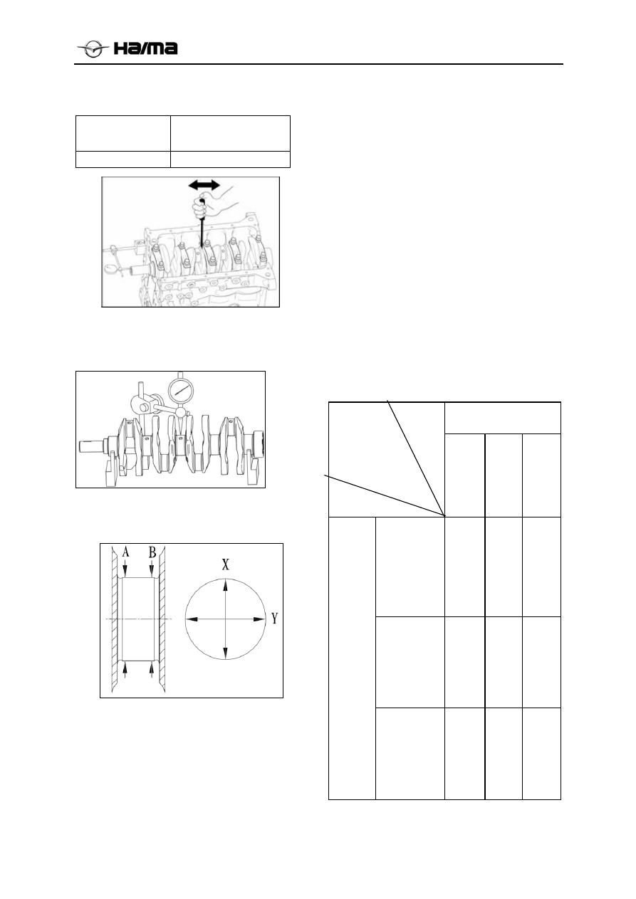
2.  Measure the crankshaft’s radial run-out. If 

necessary, replace the crankshaft.   

Maximum radial circle run-out:0.03mm 


3.  Respectively at A and B point along X and Y 

direction, measure the journal diameter. If 
necessary, replace the crankshaft.   


Main journal 

Diameter(mm) 

Standard 

45.982~46.000 

Crank pin 

Diameter(mm) 

Standard 

43.979~44.000 

4. Measure the main journal’s clearance 

according to method below.   

(1).  Remove all oil on the crankshaft journal and 

bearing seat’s internal surface. 

(2). Make the plastic gauge match the bearing 

width and then put it on the top of journal, 
keeping parallel with the axial line.   

(3).  Mount the main bearing cover (see the main 

bearing cover mounting part).   

(4).  Dismantle the main bearing cover bolt, and 

slowly take off the main bearing cover (see 
main bearing cover mounting part).   

(5).  Use the plastic gauge scale to measure the 

widest point on the plastic gauge’s extruded 
part, and then calculate out the journal 
clearance. If the clearance exceeds the 
maximum value, replace the crankshaft and 
corresponding bearing bush to ensure the 
standard clearance.   

Standard clearance: 

0.018~0.036mm


Maximum clearance: 0.1mm 

Crankshaft bearing matching table        mm 

Crankshaft main journal 

diameter 

                      Crankshaft

 
bearing thickness 


Cylinder

1:φ

45.994

~φ

46.000


2:φ

45.988

~φ

45.994


3:φ

45.982

~φ

45.988

1:φ

50.000

~φ

50.006


1# 

1.988~

1.991


2# 

1.991~

1.994


3# 

1.994

1.997

2:φ

50.006

~φ

50.012


2# 

1.991~

1.994


3# 

1.994

1.997


4# 

1.997

2.000

Cy

lin

de

m

ai

be

ari
ng 

ho

le 

di

a

m

ete

3:φ

50.012

~φ

50.018


3# 

1.994~

1.997


4# 

1.997

2.000


5# 

2.000

2.003


-------------------------------------------------------------------------------------------------------------------------------------------------------------


Electronic Fuel Injection Control System 1B

-


Chapter 2    Electronic Fuel Injection Control System 


1. Notices for Maintenance of Electronic Fuel Injection System······································1B-2 
    1.1 General Maintenance Notices······································································ 1B-2 
  1.2 Maintenance Attentions············································································· 1B-2 

    1.3 List of Maintenance Tools ···········································································1B-3 

  1.4


Manual annotation abbreviations in································································1B-5 

2. Briefings of ME7 System ················································································1B-6 
  2.1 Basic Principle························································································· 1B-6 
2.1.1 System Profile ME788-Motronic ·································································· 1B-6 
2.1.2 Torque-based ME7 System·········································································· 1B-7 
  2.2 Control signal: ME7 system’s input /output signals·············································· 1B-9 

  2.3 Introduction of System Functions····································································1B-9 
   2.3.1 Start Control ······················································································ 1B-9 
   2.3.2 Warm-up and Three-way Catalyst Converter Heating Control ···························· 1B-10 
   2.3.3 Acceleration /Deceleration and Towing Astern Oil Cutoff Control······················· 1B-10 
   2.3.4 Idle Control ······················································································· 1B-10 
   2.3.5 Close-loop Control··············································································· 1B-11 
   2.3.6 Evaporation Emission Control ································································· 1B-11 
   2.3.7 Knock Control ····················································································· 1B-11 
   2.3.8 VVT Control······················································································ 1B-11   
2.3.9Idle Start/Stop Control················································································ 1B-11 

 2.4 Introduction of System Troubleshooting Function ················································1B-11 
   2.4.1 Fault Information Record ······································································· 1B-11 
   2.4.2 Classification of Fault Types ··································································· 1B-12 

  2.4.3 Connection with Diagnostic Unit······························································ 1B-14 

3.ME7’s Overhaul and Diagnosis Flow by Fault Code ················································ 1B-14 
4.ME7’s Overhaul and Diagnosis Flow by Fault Phenomenon······································· 1B-21 

5. Functional Requirements on ME7 System’s Diagnostic Unit ······································1B-334 

 5.1 Parts Mounting Torque Specification Table ························································1B-334 

  5.2 Electronic Fuel Injection System Maintenance Specification ···································1B-34 
    5.2.1 Family Vehicle ·················································································· 1B-35 
    5.2.2 Vehicle for Lease ··············································································· 1B-35 


-------------------------------------------------------------------------------------------------------------------------------------------------------------


Electronic Fuel Injection Control System 1B

-


1. Notices for Maintenance of 
Electronic Fuel Injection System 

1.1 General Maintenance Notices   

  Only the digital multimeter can be used to 

inspect the electronic fuel injection 
system.  

  Original parts and components shall be 

used in maintenance work, or electronic 
fuel injection system’s normal running 
cannot be ensured.   

  Only the lead-free gasoline can be used 

during the maintenance process.   

  Observe standard maintenance and 

diagnosis flow to conduct maintenance.   

  Disassembly and dismantling to 

electronic fuel injection system’s 
components shall be prohibited during the 
maintenance process.    

  Handle the electronic elements (like 

electronic control unit and sensor etc) 
with caution during the maintenance 
process, and do not let them drop on the 
floor.  

  Cultivate the consciousness of 

environmental protection, and handle 
efficiently wastes resulting from the 
maintenance.  

1.2 Maintenance Attentions 

1.  Do not dismantle any of the electronic 

fuel injection system’s components or 
connectors from its mounting place 
without approval, in order to guard 
against accidental damage and prevent 
foreign objects like water and oil stain 
from entering the connector, which may 
affect the electronic fuel injection 
system’s normal running.   

2.  When disconnecting and connecting the 

connector, place the ignition switch to the 
“OFF” position, or the electric elements 
will incur damage.   

3.  When conducting the fault heating 

condition simulation or other 
maintenance jobs that may lead to 
temperature rise, make the temperature of 
electronic control unit stay below 80 . 


4.  The electronic fuel injection system’s oil supply 

pressure is relatively high (350kPa or so), and all 
fuel pipelines adopt the fuel pipe resisting high 
pressure. Even if the engine does not run, the oil 
pipeline will keep a relatively high fuel pressure. 
Due to this, do not dismantle the oil pipe at 
discretion during the maintenance process. In the 
occasion where the fuel system shall be 
maintained, pressure discharge treatment is needed 
before the oil pipe is dismantled, with pressure 
discharge method as follows: start the engine and 
make it run at idle speed, connect it with the 
diagnosis instrument, enter the “Actuator Test”, 
and turn off the fuel pump till the engine stops 
automatically. Dismantling of oil pipe and 
replacement of fuel filter shall be completed by 
maintenance professionals in the place with sound 
ventilation condition.   

5.  When dismantling the electric fuel pump from the 

fuel tank, do not power on the oil pump, in order 
to avoid electric sparks and fire disaster.   

6.  Running experiment to fuel pump shall not be 

conducted in a dry state or in water, or its service 
life will be shortened. In addition, do not mistake 
the fuel pump’s negative and positive electrodes.   

7.  When inspecting the ignition system, spark test 

shall not be conducted until it is necessary, and 
also the spark test time shall be as short as possible. 
During the testing process do not turn on the 
throttle or much unburned gasoline will flow into 
the exhaust pipe, which will in turn result in 
damage to the three-way catalyst converter.   

8.  Since the idle adjustment is completed totally by 

the electronic fuel injection system, there is no 
need to conduct manual adjustment. When leaving 
the factory, throttle’s accelerator stop bolt has been 
adjusted by the manufacturer, and users’ 
adjustment to its original location is prohibited.   

9.  When connecting with the accumulator, do no 

mistake the accumulator’s negative and positive 
electrodes, or the electronic elements will incur 
damage. In this system, minus earth is adopted.   

10. During the engine running process, do not 

dismantle the accumulator cable.   

11. Before executing the electric welding in the vehicle, 

dismantle the accumulator’s negative/positive 
cables and electronic control unit.   

12. Do not test the parts’ electric signal input/output by 

penetrating the cable sheath.

-------------------------------------------------------------------------------------------------------------------------------------------------------------


Electronic Fuel Injection Control System 1B

-


1.3 List of Maintenance Tools   


Tool name: Electronic fuel injection system diagnosis 
instrument  

Function: 

Read/clear electronic fuel injection system’s faults, 
read/clear electronic fuel injection system’s fault code, 
observe the dataflow and parts action test etc.   

(Picture here is only for your reference) 


Tool name: Electronic fuel injection system commutator 

Function: 

Inspect the electric signal at the electronic control unit’s 
every pin, and inspect the cable condition etc.   


Tool name: Ignition Timing Lamp   

Function: 

Inspect the engine’s ignition timing etc.   


Tool name: Digital Multimeter 

Function: 

Inspect the electronic fuel injection system’s 
characteristic parameters like voltage, current, and 
resistance etc.   

-------------------------------------------------------------------------------------------------------------------------------------------------------------


Electronic Fuel Injection Control System 1B

-


Tool name: Vacuum Meter   

Function: 

Inspect the pressure in the intake manifold.   


Tool name: Cylinder Pressure Gauge   

Function: 

Inspect every cylinder’s pressure.   


Tool name: Fuel Pressure Gauge   

Function: 

Inspect the fuel system’s pressure, and judge the fuel 
system’s fuel pump extrusion as well as the pressure 
regulator’s working condition.   


Tool name: Tail gas analyzer 

Function: 

Inspect the vehicle’s tail gas emission, which helps locate 
the electronic fuel injection system’s faults.   

-------------------------------------------------------------------------------------------------------------------------------------------------------------


Electronic Fuel Injection Control System 1B

-


Tool name: Fuel Injector Cleaning Analyzer 

Function: 

Make cleaning analysis on the fuel injector 

1.4 Manual annotation abbreviations in 

DG 

Speed sensor;    DVE Electronic throttle body;    FPM Accelerator pedal;    DR Fuel pressure regulator 

DS-S-TF 

Air intake pressure and temperature sensor 

ECU Electronic 

control 

unit 


EKP Fuel 

pump 

EMS 

Engine management system 

EV Injector 

LSF 

Oxgen sensor(Heating type) 

KS Knock 

sensor 

KSZ 

Fuel distribution pipe assembly 

KVS 

Fuel distribution pipe 

PG Phase 

sensor 

ROV 

Ignition system with the distributor; RUV Ignition system without the distributor; TEE Fuel pump bracket 

assembly 

TEV 

Carbon canister control valve 

TF-W 

Coolant temperature sensor 

ZSK Ignition 

coil 

VVT     Variable valve timing system  

DS-D2    Brake vacuum sensor 

HFM 

Air Flow Meter 

DV 

Turbocharger pressure relief valve 

WGV Turbocharger 

exhaust 

valve 


-------------------------------------------------------------------------------------------------------------------------------------------------------------


Electronic Fuel Injection Control System 1B

-


2. Briefings of ME7 System   

2.1 Basic Principle   

2.1.1 System Profile ME7-Motronic 

Engine management system usually consists of sensor, microprocessor (ECU), and actuator, which is used 
to control the air absorption, oil injection volume, and ignition advance angle during the engine running 
process. See Fig. 2.1 for its basic structure.   


Fig. 2.1 Components of Engine Electric Control System 

In the engine’s electric control system, sensor 

serves as the input part, which is used to measure 
different physical signals (like temperature and 
pressure) and convert them into corresponding 
electric signals. In addition, ECU is used to receive 
the sensor’s input signal, and conduct computation 
processing according to preset program, during 
which control signals produced will be outputted to 
the power drive circuit. By driving different 
actuators to execute different actions, the power 
drive circuit enables the engine to run according to 
scheduled control strategy. In the meantime, 
ECU’s fault diagnosis system monitors all 
components of the system or their control 
functions. Once the fault has been detected and 

confirmed, the fault diagnosis system will save the 
fault code, and invoke the “Limp Home” function. 
When detecting that the fault has been eliminated, 
the fault diagnosis system will resume the normal 
value.  

ME7 engine electronic control management 

system is characterized by adoption of 
torque-based control strategy, which aims to link 
different control objectives. That is the only 
method in which different functions can be 
integrated into the ECU’s different models 
according to the engine and vehicle model. See Fig. 
2.2 for structure of the ME7 Engine Electronic 
Control System


Fig. 2.2: Structure of ME7 Engine Electronic Control System 

Sensor 

Diagnosis

EUC 

Diagnosis

Actuator 

Engine 

-------------------------------------------------------------------------------------------------------------------------------------------------------------


Electronic Fuel Injection Control System 1B

-


ME7 Engine Electronic Control System’s basic 
components include: 

Electronic control unit (ECU) 

Electronic accelerator pedal   

Air quality flowmeter (depending on project) 

Fuel injector intake pressure /temperature 
sensor(depending on project) 

Electronic fuel pump 

Coolant temperature sensor 

Fuel pressure regulator   

Electronic throttle body   

Oil pump bracket   

Phase sensor 

Fuel distribution pipe 

Rotating speed sensor 

Carbon canister control valve   

Knock sensor 

Ignition coil   

VVT controller   

Oxygen sensor 

Brake vacuum sensor (idle start/stop) 

ME7-Motronicengine Management System is a 
gasoline engine control system subject to 
electronic operation, and it provides lots of control 
features relating to operators and 
vehicles/equipments. It is worth pointing out that 
the system adopts open-loop and close-loop 
(feedback) control mode, which can provide 
different control signals for the engine’s running. 
Major functions of the system include: 

1)  Basic management functions of the engine in 

physical model:   

  Torque-based system structure   

  Cylinder load determined by the intake 

pressure sensor/air flow rate sensor 

  Gas mixture control function improved in 

static and dynamic state.   

  Close-loop control 

  Sequential fuel injection cylinder by cylinder   

  Ignition timing, including knock control 

cylinder by cylinder   

  Emission control function   

  Catalyst heating   

  Carbon canister control 

  Idle control   

  Limp home   

  Speed sensing by the incremental system   

  VVT control   

  Idle start/stop 

2) Additional 

functions 


  Burglar alarm   

  Connection between the torque and external 

systems (like driving mechanism or vehicle 
dynamic control)   

  Control over several engine parts and 

components  

  Provision of interface on EOL-programming 

tools and maintenance tools   

3) Online 

OBD 

Diagnosis 


  Complete a series of OBD functions   

  Management system used in diagnosis   


2.1.2 Torque-based ME7 System   

In the ME7’s torque-based engine management 
system, all of the engine’s internal and external 
demands shall be defined according to the engine’s 
torque or efficiency requirements (see Fig. 2.3). 
Different engine demands will be converted into the 
torque or efficiency’s control variables, and then 
these variables will be firstly processed in the central 
torque demanding coordinator module. By 
sequencing these contradictory requirements by 
priority, ME7 system will execute the most important 
requirement, and then it takes advantage of torque 
conversion module to acquire needed engine control 
parameters like fuel injection time and ignition timing 
etc. Meanwhile, execution to such control variable 
will not affect other variables, which is right the 
strong point of the torque-based control system.   

Likewise, during the engine matching process, the 
torque-based control system has independent 
variables, and so only the engine data is required 
when matching the engine characteristic curve and 
map, and there is no interference with other 
functions and variables. That in turn avoids 
repetitive marking, simplifies the matching process, 
and reduces the matching cost. 

-------------------------------------------------------------------------------------------------------------------------------------------------------------


Electronic Fuel Injection Control System 1B

-


Fig. 2.3: Structure of ME7’s Torque-based System 

-------------------------------------------------------------------------------------------------------------------------------------------------------------


Electronic Fuel Injection Control System 1B

-


In comparison with previous Collection M 
engine electronic fuel injection management 
system, ME7 system has the following 
characteristics:  

  All-new engine function structure with torque 

being the variable, which is easily compatible 
with other systems and has strong scalability; 

  All-new modularized software and hardware 

structure that is highly transplantable; 

  Model-based engine characteristics maps 

independent to one another, which helps 
simplify the marking process; 

  Sensor with phase, and sequential fuel 

injection facilitates the improvement of 
emission; 

  System’s integration with anti-theft function; 

  Coordinate different torque requirements in a 

centralized manner to improve the driving 
performance; 

  16-bit CPU, 40MHz clock frequency, and 

768k cache; 

  The system is scalable according to future 

demands like emission standard OBDII.   

2.2 Control signal: ME7 system’s input /output 
signals  

In the ME7 system, ECU’s major sensor input 
signals include:   

  Air flow signal 

  Intake pressure signal   

  Accelerator pedal signal   

  Intake temperature signal 

  Throttle angle signal   

  Coolant temperature signal   

  Engine rotating speed signal   

  Phase signal   

  Knock sensor signal   

  Oxygen sensor signal   

  Vehicle speed signal   

  A/C pressure signal   

  Brake signal   

  Brake vacuum degree signal (dedicated to 

start/stop) 

  Neutral position signal (dedicated to 

start/stop) 

  Clutch top switch signal (dedicated to 

start/stop) 

  Clutch bottom switch signal (dedicated to 

start/stop) 

  Accumulator sensor signal (dedicated to 

start/stop) 

  Engine compartment cover signal (dedicated 

to start/stop) 

  Door signal (dedicated to start/stop) 

After entering the ECU, above information will be 
processed to produce the needed actuator control 
signals, which will be amplified in the output drive 
circuit and transmitted to corresponding actuators. 
These control signals include: 

  Opening of electronic throttle 

  Fuel injection timing and oil injection’s 

duration  

  Fuel pump relay   

  Opening of carbon canister control valve   

  Ignition coil’s angle of attachment and 

ignition advance angle   

  A/C compressor relay   

  Cooling fan relay 

  Starter relay   

  VVT angle   

  Turbocharger pressure relief valve 

  Turbocharger exhaust valve 

2.3 Introduction of System 
Functions  

2.3.1 Start Control   

During the starting process, special calculation 
method will be adopted to control the charge, fuel 
injection, and ignition timing. At the initial phase 
of this process, air in the intake manifold keeps 
still, and intake manifold’s internal pressure 
reading is equal to the ambient atmosphere 
pressure. When the throttle is closed, the idle speed 
regulator is assigned a fixed parameter according 
to the starting temperature.   

-------------------------------------------------------------------------------------------------------------------------------------------------------------


Electronic Fuel Injection Control System 1B

-

10 


In the similar process, the given “Fuel Injection 
Timing” is assigned the initial injection pulse.   

Fuel injection volume varies according to the 
engine temperature, in order to facilitate the 
formation of oil film on the intake manifold and 
cylinder’s walls. Therefore, when the engine 
reaches a given rotating speed, thick gas mixture 
shall be added.   

Once the engine starts running, the system will 
immediately reduce the starting excess fuel. When 
the starting process ends (600…700min-1), the 
starting excess fuel is completely cancelled.   

During the engine starting process, the ignition 
angle is being adjusted constantly, and it varies 
according to engine temperature, intake 
temperature, and engine’s rotating speed.   

Note: As for vehicles with start/stop function, 
vehicle starting can be determined according to the 
vehicle gear and clutch information. If the 
transmission is in gear and engages with the clutch, 
starter running shall be prohibited.   

2.3.2 Warm-up and Three-way Catalyst 
Converter Heating Control   

When the engine has been started at low 
temperature, cylinder charge, fuel injection, and 
electronic ignition will be adjusted to offset the 
engine’s higher torque requirements. Such a 
process will continue till appropriate temperature 
threshold has been hit.   

Meanwhile, speedy heating to three-way catalyst 
converter is most important, because speedy 
transformation into three-way catalyst converter 
running will help reduce emission of waste gas 
considerably. In such a working condition, ignition 
advance angle should be postponed, in order to heat 
the three-way catalyst converter by waste gas.   

2.3.3 Acceleration /Deceleration and 
Towing Astern Oil Cutoff Control   

Some of the fuel that has been injected into the intake 
manifold will not duly flow into the cylinder to 
partake into the subsequent combustion. On the 
contrary, it will produce a layer of oil film on the 
wall of the intake manifold. With improvement of the 
load and extension of the fuel injection duration, fuel 
deposited in the oil film will increase sharply.   

When the throttle opening increases, some 
injected fuel will be absorbed by the oil film. Due 
to this, supplementary fuel shall be injected to 
prevent the gas mixture from getting thin during 
the acceleration process. Once the load coefficient 

decreases, additional fuel included in the fuel film 
on the intake manifold wall will be released again. 
Then, injection duration must decrease during the 
deceleration process.   

Towing astern or traction condition refers to the 
situation in which the power at the flywheel from the 
engine is negative. In this case, engine friction and 
pump gas loss can be used to make the vehicle 
decelerate. When the engine stays in the towing 
astern or traction condition, the oil injection will be 
cut off to reduce the fuel consumption and waste gas 
emission. More importantly, the process will help 
protect the three-way catalyst converter.   

Once the rotating speed declines to the given rotating 
speed (above idle speed) for recovery of oil supply, 
the oil injection system will resume the oil supply. As 
a matter of fact, among the ECU’s programs there is 
a range for recovery of rotating speed, and it varies 
with change of parameters like engine temperature 
and engine rotating speed’s dynamic change. Also, it 
calculates the rotating speed to prevent it from 
declining to specified minimum threshold.   

Once the injection system resumes the oil supply, 
the system will begin using the initial injection 
pulse to supply the additional fuel, in addition to 
reconstructing the oil film on the intake manifold’s 
wall. After recovery of the fuel injection, 
torque-based control system will slow and stabilize 
the engine torque’s increase (smooth transition).   

2.3.4 Idle Control   

At the idle speed, engine will not offer torque to 
the flywheel. To make sure that the engine can run 
stably at a low idle speed, the close-loop idle 
control system must maintain the balance between 
the torque and the engine’s “Power Consumption”, 
and it will generate a given power during the idling 
process, in order to meet different load requirements, 
which arise from engine crankshaft, gas distribution 
mechanism, and auxiliary components (like friction 
in the water pump).   

ME788 System adopts the torque-based control 
strategy, which, based on close-loop idle control, 
determines the engine torque output that is required 
to maintain the idling speed in any working condition. 
Such torque output increases with decline of the 
engine’s rotating speed, or vice versa. By requiring 
higher torque, the system makes response to the new 
“Interference Factor”, such as the air conditioning 
compressor’s start/stop or automatic transmission 
shift. When the engine temperature is relatively low, 
torque should be increased to offset more internal 
friction loss and/or maintain higher idling speed. 
All these torque output requirements are 

-------------------------------------------------------------------------------------------------------------------------------------------------------------


Electronic Fuel Injection Control System 1B

-

11 


transmitted to the torque coordinator, which will 
make processing calculation and obtain 
corresponding charge concentration, components 
of gas mixture, and ignition timing.   

2.3 5 Close-loop Control   

Exhaust post-treatment in the three-way catalyst 
converter is an effective way to reduce density of 
harmful substances in the waste gas. Normally, 
the three-way catalyst converter is able to reduce 
HC, CO, and NOx by 98% ore more, and turn 
them into H2O, CO2, and N2. However, 
above-mentioned high efficiency can be realized 
only when the engine’s excess air factor is equal 
to 1 or so. In fact, the close-loop control aims to 
ensure that concentration of the gas mixture stays 
within such a range.   

Close-loop control system takes effect only when the 
oxygen sensor is installed. Oxygen sensor is used to 
monitor the oxygen content in the waste gas on the 
three-way catalyst converter’s side: thin gas mixture 
(λ>1) produces sensor voltage of about 100mV, and 
thick gas mixture (λ<1) produces sensor voltage of 
about 900mV. When λ is 1, the sensor voltage will 
incur a jumping. To the input signal, the close-loop 
control will make response (λ>1: too thin gas 
mixture,  λ<1: too thick gas mixture) to modify the 
control variable, and modifying factor therein will 
serve as the multiplier to modify the fuel injection 
duration.  

2.3.6 Evaporation Emission Control   

Due to transmission of external radiation heat and oil 
return radiation, fuel in the oil tank is heated to 
produce the fuel steam. Subject to the limitation of 
evaporation emission laws and regulations, steam 
brimming with lots of HC shall not be discharged 
into the air directly. In the system, fuel steam will be 
collected into the active carbon canister through the 
duct. When condition permits, fuel steam will be 
flushed and discharged into the engine to partake in 
the combustion process. Meanwhile, the flow rate of 
the flushing air current is realized by ECU that 
controls the carbon canister’s control valve. Only 
when the close-loop control system works in the 
close-loop condition can such a control run.   

2.3.7 Knock Control   

By virtue of the knock sensor that is mounted at 
the appropriate place of the engine, the system 
tests the characteristic vibration resulting from 
the knock, and then converts the vibration into 
electronic signal, in order to transmit it in the 
ECU for handling. By adoption of special 
processing algorithm, ECU tests if there is knock 
phenomenon at every cylinder’s combustion 

cycle. Once there is knock, ECU will trigger the 
knock close-loop control. After the knock danger 
is eliminated, the affected cylinder’s ignition will 
be gradually advanced to the preset ignition 
advance angle again.   

Knock control’s threshold is applicable to fuel of 
different working conditions and different 
grades.  

2.3.8 VVT Control   

By controlling the intake/exhaust camshaft phase, 
the system can efficiently reduce the engine’s 
emission at low speed and improve its torque at 
high speed. According to the vehicle’s running 
condition and the driver’s driving intention, the 
ECU can calculate out the intake/exhaust 
camshaft’s target phase, as well as realize the 
close-loop control to the camshaft phase according 
to the phase information acquired from the phase 
sensor. Compared with the engine without VVT 
system, the engine with VVT system can 
efficiently reduce oil consumption and emission as 
well as raise the maximum power.   

2.3.9 Idle Start/Stop Control   

By analyzing the driver’s driving intention, the 
system will realize the automatic idle stop/start at a 
proper time. By analyzing such information as 
clutch pedal, neutral gear, driving speed, brake 
vacuum degree, accumulator state, door, and engine 
compartment cover etc., idle start/stop control will 
determine if the automatic stop/start conditions have 
been met. During the normal driving process, drivers 
need to conduct any additional operation to realize 
the automatic idle stop/start.   

Since the idle start/stop control provides the complete 
vehicle with starter relay, there will be two additional 
functions like automatic start after stalling and 
starter’s failure in running when gearing chain 
engages (transmission is in gear and engages with 
clutch), which will do good to fresh drivers. In 
addition, the idle start/stop control can help reduce 
the complete vehicle’s oil consumption and gas 
emission.  

2.4 Introduction of System 
Troubleshooting Function   

2.4.1 Fault Information Record 

Electronic control unit constantly monitors the 
sensor, actuator, relevant circuits, fault indicators, 
and accumulator voltage etc., and even the 
electronic control unit itself, in addition to 
conducting the reliability test to the sensor output 
signal, actuator drive signal, and internal signals 

-------------------------------------------------------------------------------------------------------------------------------------------------------------


Electronic Fuel Injection Control System 1B

-

12 


(like close-loop control, coolant temperature, 
knock control, idling speed control, and 
accumulator voltage control etc). Once there is 
fault at certain link or a given signal is unreliable, 
the electronic control unit will immediately set the 
fault information record in RAM fault memory, 
and save it in the form of fault code, which will be 

displayed according to the fault occurrence 
sequence. According to the fault frequency, faults 
can be classified into “Steady-state Faults” and 
“Sporadic Faults” (like the faults resulting from 
short-lived open circuit or poor contact between 
connectors)


Fig. 2.4 Electronic Fuel Injection System’s Troubleshooting Principle 

2.4.2 Classification of Fault Types 

Diagnostic Fault Path and Fault Categories   

Diagnostic fault path (DFP) is, in fact, a 
sub-function for fault diagnosis that is used to 
inspect functions of a given sensor, actuator, or 
others in the EMS system. By respective 
diagnostic path, the fault information will be 
transmitted to the fault diagnosis management 
module, which will take corresponding actions 
and determine if the fault lamp should be activated 
or the fault should be displayed on the diagnostic 
unit. When a fault is detected at a given DFP, the 
fault diagnosis management module will make 
definite the fault type. Usually, the fault types 
include: 

B_mxdfp Maximum fault, signal goes beyond the 
upper limit of the normal range.   

B_mndfp Minimum Fault, the signal goes beyond 
the lower limit of the normal range.   

B_sidfp signal fault, without signal.   

B_npdfp unreasonable signal, with signal, but 
the signal is unreasonable.   

Definitions of Fault Types   

In this project there are 10 fault types. Closed fault 
path is defined as “Class0”, namely, the fault 
information will not enter the fault memory, and 
also the diagnostic unit will not read the fault. In 
addition, faults of Class2, Class3, Class4, Class5, 

Class6, Class7, Class11, Class12, and Class13 
belong to those fault types that have been defined 
by the system in a uniform manner.   

Class2: fault is inputted into the fault memory upon 
taking place; DFP fault types relating to misfire are 
usually defined as Class 2. As for the misfire fault 
resulting in damage of catalyst, the MIL lamp will 
flash in no time to prompt the driver. As for the 
misfire fault resulting in deterioration of emission, if 
the misfire fault of corresponding extent has been 
fully detected in three consecutive driving cycles, the 
MIL lamp will be activated, and also the fault will be 
displayed on the diagnostic unit. If the fault fails to 
be confirmed or eliminated in 40 driving cycles 
(namely, in a warm-up cycle, E_xxx=1, but Z_xxx

0), the fault information will be deleted from the 

fault memory. if the fault disappears before the fault 
confirmation and never occurs within 40 driving 
cycles, the fault information will be deleted from the 
fault memory; If the fault disappears after being 
confirmed, the fault information cannot be deleted 
from the fault memory until it does not occur within 
40 warm-up cycles, and the fault priority is defined 
as 20. After the fault confirmation, SVS lamp is off. 
If the fault disappears after the fault confirmation and 
never occurs within three driving cycles, it means 
that the fault has been corrected.   

Class3: fault is inputted into the fault memory upon 
taking place. After the fault confirmation, the MIL 
lamp is activated, and the fault confirmation needs 
three driving cycles, with fault being displayed on the 
diagnostic unit. If the fault fails to be confirmed or 

-------------------------------------------------------------------------------------------------------------------------------------------------------------


Electronic Fuel Injection Control System 1B

-

13 


eliminated within 40 warm-up cycles(namely, in a 
warm-up cycle, E_xxx=1, but Z_xxx=0), the fault 
information will be deleted from the fault memory; if 
the fault disappears before the fault confirmation and 
never occurs within 40 warm-up cycles, the fault 
information will be deleted from the fault memory; If 
the fault disappears after being confirmed, the fault 
information cannot be deleted from the fault memory 
until it does not occur within 40 warm-up cycles; and 
the fault priority is defined as 30; after the fault 
confirmation, SVS lamp is off; If the fault disappears 
after fault confirmation and never occurs within three 
driving cycles, it means the fault has been corrected..   

Class4:fault is inputted into the fault memory upon 
taking place. After 2.5s since the fault occurs, the 
MIL lamp will be activated, and also the fault is 
displayed on diagnostic unit; If the fault fails to be 
confirmed or eliminated within 40 warm-up 
cycles(namely, in a warm-up cycle, E_xxx=1, but 
Z_xxx=0), the fault information will be deleted from 
the fault memory; if the fault disappears before the 
fault confirmation and never occurs within 40 
warm-up cycles, the fault information will be deleted 
from the fault memory; If the fault disappears after 
being confirmed, the fault information cannot be 
deleted from the fault memory until it does not occur 
within 40 warm-up cycles; and the fault priority is 
defined as 30; after the fault confirmation, SVS lamp 
is off; If the fault disappears after fault confirmation 
and never occurs within three driving cycles, it means 
the fault has been corrected..   

Class5:fault is inputted into the fault memory upon 
taking place; after the fault confirmation, MIL lamp is 
off; fault confirmation needs 3 driving cycles; the 
fault is displayed on diagnostic unit; If the fault fails 
to be confirmed or eliminated within 40 warm-up 
cycles(namely, in a warm-up cycle, E_xxx=1, but 
Z_xxx=0), the fault information will be deleted from 
the fault memory; if the fault disappears before the 
fault confirmation and never occurs within 40 
warm-up cycles, the fault information will be deleted 
from the fault memory; If the fault disappears after 
being confirmed, the fault information cannot be 
deleted from the fault memory until it does not occur 
within 40 warm-up cycles; and the fault priority is 
defined as 40; after the fault confirmation, SVS lamp 
is off; If the fault disappears after fault confirmation 
and never occurs within three driving cycles, it means 
the fault has been corrected..   

Class6: fault is inputted into the fault memory upon 
taking place; after the fault confirmation, MIL lamp is 
off; fault will be confirmed upon taking place; the 
fault is not displayed on the diagnostic unit;If the fault 
fails to be confirmed or eliminated within 40 
warm-up cycles(namely, in a warm-up cycle, E_xxx

1, but Z_xxx=0), the fault information will be 

deleted from the fault memory; If the fault disappears 
after being confirmed, the fault information cannot be 
deleted from the fault memory until it does not occur 
within 40 warm-up cycles; and the fault priority is 
defined as 50; after the fault confirmation, SVS lamp 
is off; If the fault disappears after the fault 
confirmation and never occurs within 1.2s, it means 
the fault has been corrected.   

Class7:fault is inputted into the fault memory upon 
taking place; after the fault confirmation, MIL 
lamp is off; fault will be confirmed upon taking 
place; the fault is not displayed on the diagnostic 
unit;If the fault fails to be confirmed or eliminated 
within 40 warm-up cycles(namely, in a warm-up 
cycle, E_xxx = 1, but Z_xxx = 0), the fault 
information will be deleted from the fault memory; 
If the fault disappears after the fault confirmation, 
the fault information cannot be deleted from the 
fault memory until it does not occur within five 
warm-up cycles, and the fault priority is defined as 
50; after the fault confirmation, SVS lamp is off; If 
the fault disappears after the fault confirmation and 
never occurs within 120ms, it means the fault has 
been corrected.   

Class11:fault is inputted into the fault memory upon 
taking place; after the fault confirmation, MIL lamp is 
activated; fault confirmation needs 3 driving cycles;  
the fault is displayed on diagnostic unit; If the fault 
fails to be confirmed or eliminated within 40 
warm-up cycles(namely, in a warm-up cycle, E_xxx

1, but Z_xxx=0), the fault information will be 

deleted from the fault memory; if the fault disappears 
before the fault confirmation and never occurs within 
40 warm-up cycles, the fault information will be 
deleted from the fault memory; If the fault disappears 
after being confirmed, the fault information cannot be 
deleted from the fault memory until it does not occur 
within 40 warm-up cycles; and the fault priority is 
defined as 20; after the fault confirmation, SVS lamp 
is off; If the fault disappears after the fault 
confirmation and never occurs within 4 driving cycles, 
it means the fault has been corrected.   

Class12:fault is inputted into the fault memory 
upon taking place; after the fault confirmation, 
MIL lamp is off; fault is confirmed upon taking 
place, and it is not displayed on the diagnostic unit; 
If the fault fails to be confirmed or eliminated 
within 40 warm-up cycles (namely, in a warm-up 
cycle, E_xxx = 1, but Z_xxx = 0), the fault 
information will be deleted from the fault memory; 
if the fault disappears before the fault confirmation 
and never occurs within 40 warm-up cycles, the 
fault information will be deleted from the fault 
memory; If the fault disappears after being 

-------------------------------------------------------------------------------------------------------------------------------------------------------------


Electronic Fuel Injection Control System 1B

-

14 


confirmed, the fault information cannot be deleted 
from the fault memory until it does not occur 
within 40 warm-up cycles; and the fault priority is 
defined as 50; after fault confirmation, SVS lamp 
is activated; If the fault disappears after the fault 
confirmation and never occurs within 120, it means 
the fault has been corrected, and also the SVS is 
off.  

Class13:fault is inputted into the fault memory upon 
taking place; after the fault confirmation, MIL lamp is 
activated; fault confirmation needs 3 driving cycles;  
the fault is displayed on diagnostic unit; If the fault 
fails to be confirmed or eliminated within 40 
warm-up cycles(namely, in a warm-up cycle, E_xxx

1, but Z_xxx=0), the fault information will be 

deleted from the fault memory; If the fault disappears 
before the fault confirmation and never occurs within 
40 warm-up cycles, the fault information will be 
deleted from the fault memory; If the fault disappears 
after the fault confirmation, the fault information 
cannot be deleted from the fault memory until it never 
occurs within 40 warm-up cycles; and the fault 
priority is defined as 30; after fault confirmation, SVS 
lamp is activated; If the fault disappears after the fault 
confirmation and never occurs within 4 driving cycles, 
it means the fault has been corrected, and also the 
SVS lamp is off.   

SVS Lamp Control Strategy   

In different working conditions, SVS lamps vary in 
working condition:   

1)  No blink code request, and empty fault 
memory 

When the ignition switch is turned on, ECU will 
start initialization in no time. Since the 
initialization, SVS lamp will be turned on for 4s. 
If the engine is started within 4s, SVS will 
immediately go out if the engine’s rotating speed 
(B_nmot=true) has been located.   

2)  No blink code request, there is fault in the 
fault memory   

Since the ignition switch has been turned on 
and the ECU embarks on the initialization, SVS 
lamp will remain “ON” state until the engine’s 
rotating speed has been located. If the fault 
manager requires that SVS lamp shall be turned 
on in the fault mode, the SVS lamp will remain 
“ON” state in the subsequent driving cycle.   

3)  Blink code request and empty fault memory 

If the ECU blink code request condition has been 
met (blink code request condition: ignition switch is 
turned on under the precondition of no vehicle 
speed, no engine’s rotating speed, accelerator 

pedal’s opening greater than 75%, and stepping 
down the brake pedal), SVS will work in blink code 
mode. Since the ignition switch has been turned on 
and the ECU embarks on initialization, SVS lamp 
will remain “ON” state for 4s. Then, after one 
second of interval, SVS will blink at the frequency 
of 2HZ, in order to indicate “No Fault” till the blink 
code request condition cannot be met.   

4)  Blink code request, and there is fault in fault 
memory 

If the ECU blink code request condition has been 
met (blink code request condition: ignition switch is 
turned on under the precondition of no vehicle 
speed, no engine’s rotating speed, accelerator 
pedal’s opening greater than 75%, and stepping 
down the brake pedal), SVS will work in blink code 
mode. 

Since the ignition switch has been turned on and the 
ECU embarks on initialization, SVS lamp will 
remain “ON” state for 4s. Then, after one second of 
interval, SVS will indicate the fault code (P-code) 
in the memory with a blink code. If all faults in the 
memory have been indicated by SVS lamp in the 
form blink codes, and blink code request condition 
is still met, the SVS lamp will go out till blink code 
request condition cannot be met.   

2.4.3 Connection with Diagnostic Unit 

This system adopts CAN communication protocol 
and ISO 15031-3 standard diagnosis connector (see 
Fig.2.5). Such a standard diagnosis connector, in 
the form of bus connector, is fixed at the position 
between the cab’s steering shaft and the vehicle’s 
medial axis. Pin 4, 6, 14, and 16 of the standard 
diagnosis connector are used in the engine’s 
management system EMS. Of which, the standard 
diagnosis connector’s Pin 4 links with the earth 
wire in vehicle, Pin 6 serves as the engine data 
cable CAN_H’s lead, Pin 14 serves as the engine 
data cable CAN_L’s lead, and Pin 16 connects with 
the accumulator’s positive electrode.   


Fig. 2.5: ISO15031-3 Standard Diagnosis 
Connector 

Through “CAN” cable, ECU can communicate 
with the external diagnostic unit. See GEELY 
Instruction on Diagnostic Unit for detailed 
operations of the diagnostic unit.   

-------------------------------------------------------------------------------------------------------------------------------------------------------------


Electronic Fuel Injection Control System 1B

-

15 


3 ME7’s Overhaul and Diagnosis Flow by 
Fault Code 

Explanations: 

1.  The overhaul cannot be executed only when 
current fault has been confirmed as “Steady-state” 
fault, or the diagnosis error will take place.   

2.  Multimeter required refers to the digital 
multimeter, and analogue multimeter shall not be 
used to inspect the electronic fuel injection 
system’s lines.   

3.  In the case of overhauling the vehicle with 
anti-theft system, if the ECU will be replaced, 
programming to ECU shall be done after the 
replacement.  

4.  If the fault code indicates that a given circuit has 
too low voltage, it means that there likely exists short 
circuit to the earth in the circuit. If the fault code 
indicates that a given circuit has too high voltage, it 
means that there likely exists short circuit to the 
battery in the circuit. If the fault code indicates that 

there is fault at a given circuit, it means that there 
likely exists open circuit or several types of faults in 
the circuit.   

Diagnosis help: 

1.  If the fault code cannot be cleared, the fault 
belongs to “Steady-state” fault. If the fault belongs 
to sporadic fault, emphasis should be put on the 
inspection to wiring connector’s looseness.   

2.  No abnormal situation after preceding 
inspection; 

3.  During the overhaul process, do not overlook 
other factors’ influence on the system, such as 
automobile maintenance, cylinder pressure, and 
mechanical ignition timing etc.   

4.  Replace ECU for further test.   

If the fault code can be cleared, the fault cause 
should be attributed to ECU. However if the fault 
code cannot be cleared, remount original ECU and 
repeat the workflow for further overhaul work.


INDEX PCODES 

UAES Explanations 

CLASS  MIL 

SVS

P000A 

Slow intake VVT response 

× 

× 

P0010 

VVT intake control valve circuit, open 

√ × 

3 P0012 

Intake VVT fails to stay at defaulted position when 
starting 

5 × × 

4 P0016 

Improper relative position between crankshaft and 
camshaft 

√ × 

P0030 

Upstream oxygen sensor heater control circuit, fault 

√ × 

6 P0031 

Upstream oxygen sensor heater control circuit, low 
voltage 

√ × 

7 P0032 

Upstream oxygen sensor heater control circuit, high 
voltage 

√ × 

P0033 

Discharge control valve control circuit. 

√ × 

P0034 

Discharge control valve control circuit voltage is too low.

√ × 

10 

P0035 

Discharge control valve control circuit voltage is too 
high. 

√ × 

11 

P0036 

Downstream oxygen sensor heater control circuit, fault 

√ × 

12 P0037 

Downstream oxygen sensor heater control circuit, low 
voltage, 

√ × 

13 P0038 

Downstream oxygen sensor heater control circuit, 

high 

voltage


√ × 

14 

P0053 

Upstream oxygen sensor heater resistance, improper 

√ × 

15 

P0054 

Downstream oxygen sensor heater resistance, improper 

√ × 

-------------------------------------------------------------------------------------------------------------------------------------------------------------


Content      ..     2      3      4      5     ..