Haima S5 1.5T. Service Manual - part 2


  Index      Haima     Haima S5 1.5T. Service Manual


Search            copyright infringement  


Content      ..      1      2      3      ..


Haima S5 1.5T. Service Manual - part 2


Engine block 1A-13 


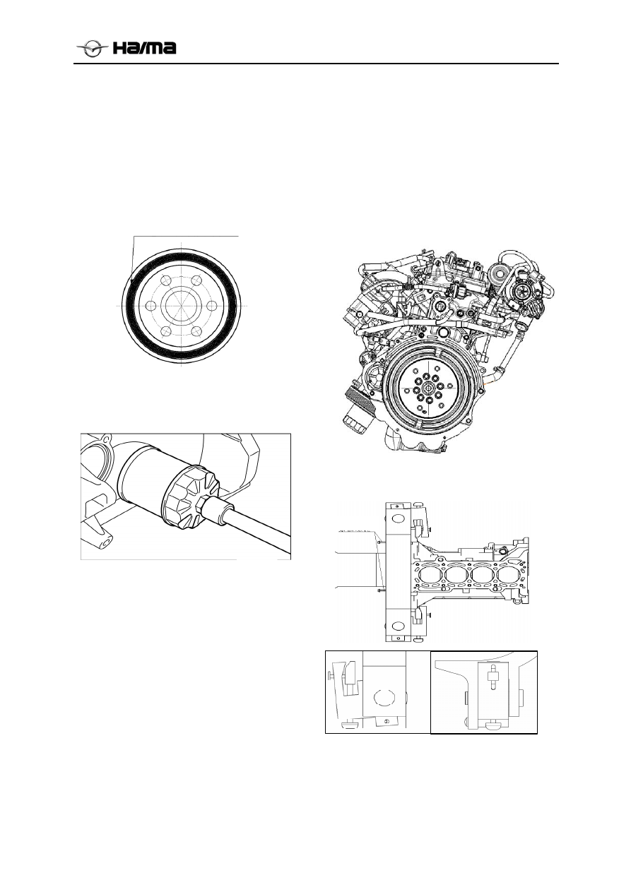
1.2.5 Replacement of Oil Filter   

1.  Dismantle the oil filter with special tools.   

2.  Rub and clean the new oil filter with a clean 

cloth.  

3.  Smear clean oil onto the new oil filter’s 

O-ring.  


4.  Mount the oil filter with special tools 

Tightening torque:

14.0~16.0N·m{1.42~

1.63kgf·m}.  

5.  Start the engine and inspect if there is leakage. 

Inspect the oil level and check if oil adding is 
needed (see Inspection of Engine Oil).   

Others  

Other inspection and maintenance like power 
generator inspection and starter inspection etc can 
be conducted on the complete vehicle. See this 
manual and corresponding complete vehicle 
maintenance manual for processing procedures.   

1.3 Application of Engine 
Maintenance Platform   

1.3.1 Mount the Engine onto 
Maintenance Platform   

1.  Lift the engine, and align the cylinder body’s 

pin hole to the maintenance platform’s 
mounting dowel pin to mount the engine(see 
the figure).   


2. 

Mount the work fixture according to the 

figure and lock it. 


3.  Adjust the fixing bolt to appropriate place and 

prevent the engine mounting from getting 
loose.  

4.  Pour the engine oil into specified vessel.   

Smear clean oil onto the 
new oil filter’s O-ring. 

Fixing bolt

-------------------------------------------------------------------------------------------------------------------------------------------------------------


Engine block 1A-14 


5.  Mount the new oil drain plug, and tighten the 

oil drain plug. tightening torque: 30 ~
41N·m{3.1~4.2kgf·m} 

1.3.2 Dismantle the Engine from 
Maintenance Platform   

Dismantle the engine from the maintenance 
platform according to steps reverse to “Mount 
the Engine onto Maintenance Platform”.   

Notice 

  The engine maintenance platform’s 

self-locking brake system may lose efficacy 
in an unbalanced state, for instance, the 
engine maintenance platform suffers 
unbalance due to sudden and rapid action 
resulting from the engine mounting onto and 
dismantling from the platform, which will 
result in danger. Due to this, to ensure the 
engine and the entire maintenance 
platform’s balance during the operation 
process, the maintenance platform’s rotary 
handle shall be held tightly in hands during 
the engine tilting process.   

1.4 Power Generator and Starter   

1.4.1 Power Generator’s 
Dismantling/Mounting 

Warning 

  When dismantling /mounting the power 

generator on the complete vehicle, the 
accumulator cable shall be dismantled firstly, 
or the power generator’s Terminal B will 
contact the vehicle body, which will lead to 
sparks and further result in personal injury 
and electric element damage.   

1.  Dismantle the power generator according to 

the sequence illustrated in the figure.   

2.  Mount the power generator according to the 

sequence reverse to the dismantling process.   

3.  Inspect the belt’s deflection /tension (see 

Inspection of the Power Generator Belt).   


1 Generator 

adjusting 

arm 

2 Generator 

belt 

3 Generator 

bolt 

4 Generator 

1.4.2 Explanations on Inspection of Power 
Generator Belt   

If necessary, inspect the power generator belt’s 
deflection and tension: see complete vehicle 
maintenance manual’s corresponding part.   

1.4.3 Explanations on adjustment to 
tension of power generator and air 
conditioning drive belts   

1.  Loosen the power generator’s bolt nut  . 


2.  Loosen the power generator’s fixing nut  . 


Use the adjusting bolt  , 

and adjust the belt 

tension and belt difference to the specified value.   

3.  Tighten the power generator pivot bolt’s nut 

: tightening 

torque:

53~60N·m


4.  Tighten the power generator’s fixing nut ②: 

tightening torque:

19~25N·m


Notice 

  If mounting the new power generator belt or 

running power generator belt for less than 5 
minutes, adjustment shall be made according 

Power 

Generator Belt

Power 

Generator 

Adjust the bolt

power generator’s 

fixing nut power 

generator’s bolt nut 

-------------------------------------------------------------------------------------------------------------------------------------------------------------


Engine block 1A-15 


to the new part’s standard value.   

  If running power generator belt for more than 

5 minutes, adjustment shall be made 
according to old part’s standard value.   

  If it fails to stay within the standard value, 

readjustment shall be made from Step 1 on.   

1.4.4 Explanations on inspection of power 
generator 

1.  Confirm if the accumulator has been charged.   

2.  Confirm if the belt’s deflection /tension stays 

within the specified range (See power 
generator part: Inspection of Power Generator 
Belt).  

3.  Turn the ignition switch to the “ON” position, 

and the charge warning lamp will turn on.   

4.  Confirm if the charge warning lamp is off 

after the engine has been put into running.   

  Note: If there is abnormal situation, see 

corresponding “Complete Vehicle Fault 
Diagnosis and Handling”.   

1.4.5 Starter Dismantling/Mounting 

Warning 

  When dismantling/mounting the starter on the 

complete vehicle, if the accumulator’s 
positive cable fails to be loosened, the 
starter’s Terminal B will connect with or 
contact the body, which will lead to sparks 
and further result in personal injury and 
electric element damage. Due to this, 
accumulator’s positive cable shall be 
dismantled firstly when the following 
operations are conducted:   

1.  Dismantle the accumulator’s positive cable.   

2.  Dismantle the starter according to the 

sequence illustrated in the figure.   

3.  Mount the starter according to the sequence 

reverse to the dismantling process.   


  Binding post B cable


  Binding post S cable


3 Starter 


1.4.6 Explanations on inspection of starter   

Accompanying inspection:   

1.  Confirm if the accumulator is charged.   

2.  Start the starter to Confirm if the starter runs 

stably and has no running noise.   

  Note: If there is abnormal situation, turn the 

ignition switch to the “START” position, and 
measure the voltage between Terminal S and 
Terminal B, and the standard voltage shall be 
greater than 8(V) 

—If the voltage stays beyond the specified range, 
overhaul the wiring harness and ignition switch.   

—If the voltage stays within the specified range, 
dismantle the starter and inspect the solenoid 
switch and starter.   

Zero-load test   

1.  Confirm if the accumulator is charged.   

2.  Connect the starter, accumulator, voltmeter 

and ammeter (see right figure).   

3.  Run the starter and Confirm if its running is 

stable.  

4.  During the starter running process, measure 

the voltage and current.   


Note: If there is abnormal situation, conduct 
repair or replacement.   

Standard voltage:11(V), standard current:<95(A) 

Ignit

io

n sw

it

ch


Accumulat

or


Terminal S

Starter

-------------------------------------------------------------------------------------------------------------------------------------------------------------


Engine block 1A-16 


1.5 Ignition, Control System   

Ignition Coil and PCV Valve 
Dismantling/Mounting 

Notice 

  When dismantling the ignition coil and spark 

plug, shield sleeve at the connecting rod can 
be easily torn. Due to this, they should be 
dismantled only when the replacement is 
necessary and tearing and damage shall be 
avoided during the dismantling process.   

1.  Dismantle parts according to sequence 

illustrated in the figure.   


    I

gnition coil 

    S

park plug   

3 PCV 

valve 

2.  Mantle parts according to sequence reverse to 

the dismantling process.   

1.51 Spark Plug Dismantling/Mounting 

Notice 

  Mount the spark plug cautiously because 

strong impact will result in spark plug 
damage.  

PCV Valve Dismantling /Inspection   

1.  Dismantle the PCV valve.   

2.  Confirm if the air ventilation in PCV valve is 

as the following table. If there is abnormal 
situation, replacement shall be conducted.   


Air Ventilation Condition Table   

Test Condition 

Test Result 

Blow to A 

There is air outflow   

from Interface B 

Blow to B 

There is no air outflow from 

Interface A 

1.5.2 Control System Parts 
Dismantling/Mounting 

1.  Dismantle parts according to sequence 

illustrated in the figure.   

2.  Mount parts according to sequence reverse to 

the dismantling process.   


1

Fuel distribution pipe assembly 

2

Oil control valve   

3

Throttle body   

4

Crankshaft position sensor  (see 
Inspection of Crankshaft Position 
Sensor) 

5

Knock sensor 

6

Oil pressure sensor 

7

Camshaft position sensor 

8

Carbon tank solenoid valve assembly 

9

Water temperature sensor  (see 
dismantling/mounting explanations) 

-------------------------------------------------------------------------------------------------------------------------------------------------------------


Engine block 1A-17 


Note: this part only lists different parts of 
the control system’s mounting conditions 
on the engine. See the complete vehicle’s 
corresponding part for relevant fault 
diagnosis and inspection. 

1.5.3 Crankshaft position sensor’s 
dismantling/mounting explanations   

1.  When mounting the crankshaft position 

sensor, smear “LOCTITE5971” onto the 
cylinder body (shade line zone).   

2.  When smearing the sealant, keep clean the 

unit surface’s bonding part.   

3.  After smearing the sealant, mount the 

crankshaft position sensor within 3 minutes.   

1.5.4 Explanations to inspection of 
crankshaft position sensor 

Clearance inspection 

Attentions  


  Under-mentioned inspection shall be 

conducted if necessary.   

1.  Confirm if the crankshaft rotating speed 

sensor is correctly mounted.   

2.  Use the plug gauge to measure the clearance 

between signal wheel protrusion platform and 
crankshaft rotating speed sensor. 

Notice 

  If the clearance is incorrect, adjust the 

crankshaft rotating speed sensor or inspect if 
there is torsion and indentation in the signal 
wheel’s protrusion part. (If have, replace the 
crankshaft signal panel).   

Standard clearance value:0.5~1.5mm 


1.5.5 Explanations on water temperature 
sensor dismantling/mounting 

Use the sleeve to dismantle the water temperature 
sensor.  


Zone for smearing 
the sealant 

Crankshaft 
position sensor


Crankshaft 
signal panel


Clearance 

-------------------------------------------------------------------------------------------------------------------------------------------------------------


Engine block 1A-18 


1.6 Intake and Exhaust System 

1.6.1 Intake and Exhaust System Dismantling/Mounting 

1.  Dismantle parts according to sequence illustrated in the figure.   

2.  Mount the parts according to the sequence reverse to the dismantling process.   


Throttle body   

10

Turbocharger oil return pipe 

Throttle body seal ring(see Mounting 
Instruction) 

11 Turbocharger 

Intake manifold 

12

Turbocharger gasket 

Intake manifold seal ring(see 
Mounting Instruction) 

13

Heat shield bracket 

Exhaust pipe gasket


14

Turbocharger bracket 

Turbocharger heat shield 

15

Exhaust manifold’s upper heat shield 

Turbocharger oil inlet pipe 

16

Exhaust manifold 

Turbocharger water return pipe 

17

Exhaust manifold’s sealing gasket 

Turbocharger water inlet pipe 


-------------------------------------------------------------------------------------------------------------------------------------------------------------


Engine block 1A-19 


1.6.2 Explanations on intake manifold 
dismantling  

1.  Dismantle parts according to the sequence 

illustrated in the figure.   

2.  Mount parts according to the sequence 

reverse to the dismantling process.   


1.6.3 Explanations on the intake manifold 
seal ring mounting   

During the mounting process, mount the seal ring 
into the intake manifold’s slot, and wedge the seal 
ring’s anti-mistake mark into the intake manifold’s 
locating slot.   

Caution 

  Prior to the mounting, inspect if there is 

damage on seal ring. If there is, replacement 
shall be made.   


1.6.4 Explanations on the throttle body 
seal ring mounting   

During the mounting process, mount the seal ring 
into the intake manifold’s slot, and wedge the seal 
ring’s anti-mistake mark into the intake 
manifold’s locating slot. 


Notice 

  Prior to the mounting, inspect if there is 

damage on seal ring. If there is, replacement 
shall be made. 

1.6.5 Explanations on the exhaust 
manifold dismantling   

1.  Dismantle parts according to the sequence 

illustrated in the figure.   

2.  Mount parts according to the sequence 

reverse to the dismantling process.   


1.6.6 Explanations on the turbocharger 
mounting  

Notice 

  Check turbocharger installed in the front 

without foreign body, impeller rotation is 
normal. 

  Installation turbocharger gaskets should be 

checked, avoid installing dislocation. 

  Turbocharger inlet and outlet water pipe 

position do not reversed. 

1.7 Timing System 

1.7.1Timing system dismantling/mounting 

1.  Dismantle power generator belt (see power 

generator part).   

2.  Dismantle ignition coil (see the ignition part).   

3.  Dismantle cylinder head hood (see cylinder 

head hood part).   

4. Dismantle 

oil 

sump. 


5.  Dismantle oil pump and timing chain case 

assembly (see oil pump and timing chain case 
assembly part).   

6.  Dismantle parts according to the sequence 

illustrated in the figure   

7.  Mount the parts according to the sequence 

reverse to the dismantling process.   

8.  Adjust the power generator belt deflection 

/tension (see power generator part).   

Seal ring 

Locating 

Seal ring 

-------------------------------------------------------------------------------------------------------------------------------------------------------------


Engine block 1A-20 


  T

iming chain tensioner assembly 

 Tensioner arm assembly


Timing chain guide assembly


Timing chain


5  

Camshaft 

sprocket 

6    Intake VVT

 assembly


1.7.2 Explanations on timing chain 
tensioner assembly dismantling   

1.  Dismantle parts according to the sequence 

illustrated in the figure.   

2.  Mount the parts according to the sequence 

reverse to the dismantling process.   

Notice 

  Loosen the timing chain tensioner assembly 

bolt, and slowly take off the timing chain 
tensioner assembly (prevent the plunger from 
popping suddenly).   

1.7.3 Explanations on crankshaft pulley 
dismantling  

Use the special tools to secure the crankshaft for 
dismantling.  


1.7.4 Explanations on cylinder head hood 
dismantling  

Loosen the bolt according to the sequence 
illustrated in the figure.   


1.7.5 Explanations on the timing chain 
dismantling  

1.  Mount the crankshaft pulley locking bolt.   

2.  Rotate crankshaft along the clockwise 

direction, and align the gas distribution 
inspection mark.   

Notice 

  Keep the timing chain pulley’s key slot 

upward.  

  Align the gas distribution inspection mark at 

the timing chain pulley on the exhaust side of 
intake VVT.   

3.  Dismantle timing chain tensioner assembly 

(see Timing Chain Tensioner Assembly 
Dismantling).  

4.  Dismantle the tensioner arm assembly.   

5.  Dismantle the timing chain’s guide rail 

assembly.  

6.  Dismantle the timing chain.   

1.7.6 Explanations on the timing chain’s 
tensioner assembly mounting 

1.  Compress the pallet with bench clamp(see the 

figure), and insert one hard steel wire into the 
locking hole to lock the timing chain’s 
tensioner assembly.   

2.  Mount the timing chain’s tensioner assembly 

onto the cylinder body, and tighten the bolt.   


Bolt unit 

Fixture unit 

Double-ended jointing fixture

Locking hole 

Pallet compression 
direction  

Pallet 

-------------------------------------------------------------------------------------------------------------------------------------------------------------


Engine block 1A-21 


1.7.7 Explanations on the tensioner arm 
assembly mounting   

After the mounting, tensioner arm assembly shall 
not be excessively tightened, and sway the 
tensioner arm assembly to inspect if it can fall 
down freely. 

1.7.8 Explanations on timing chain 
mounting  

1.  Rotate the intake & exhaust camshaft to make 

two timing marks at the timing chain pulley 
on exhaust side of the intake VVT face 
toward specific angle. 

2.  Mount the timing chain’s guide rail assembly. 

3.  Mount the timing chain. 

Notice 

  Align the timing mark at the timing chain 

pulley on the exhaust side of the intake VVT 


4.  Mount the tensioner arm assembly (see 

tensioner arm assembly mounting 
explanations). 

Notice 

  Confirm if the timing chain is located in the 

timing chain guide rail assembly and 
tensioner arm assembly’s slot. 

5. Pull out the timing chain tensioner 

assembly’s locking pin, when the push rod is 
popped to push the tensioner arm assembly to 
compress the timing chain. 

Notice 

  Confirm if the timing chain is located in the 

tensioner arm assembly and timing chain 
guide rail assembly’s guiding slot.   

6.  Confirm if all timing marks (4) and valve 

timing mechanism have been inspected Align 
the mark (1) accurately.   

Notice 

  Camshaft timing chain pulley and VVT 

assembly timing marks are “△”, gas 
distribution inspection mark is “○”; and 
crankshaft timing chain pulley timing mark is 
semicircular groove 

  In the event of failure in aligning, dismantle 

the timing chain, and repeat the operation 
from Step 1 

7.  Rotate the crankshaft for two circles along the 

clockwise direction, and then rotate the 
crankshaft to make the intake VVT assembly 
(timing chain pulley on the intake side) align 
with two gas distribution inspection marks at 
the camshaft chain on the exhaust side.     

Notice 

  In the event of failure in aligning, repeat the 

operation from Step 1 

1.7.9 Explanations on the cylinder head 
hood mounting   

1.  Confirm if the cylinder head hood groove is 

free from oil, water, and other foreign 
objects.  

2.  Confirm if the cylinder head hood’s sealing 

gasket has been completely attached to the 
cylinder head hood’s groove.   

3.  Smear the sealant onto the joint between 

cylinder head and oil pump and timing chain 
case assembly according to the illustration.   

4.  Mount the cylinder head hood bolt according to 

the sequence reverse to the dismantling process 
of cylinder head hood (see the cylinder head 
hood dismantling part), and tighten the cylinder 
head hood bolt by step.   


tightening torque:8~10N·m


-------------------------------------------------------------------------------------------------------------------------------------------------------------


Engine block 1A-22 


1.7.10 Explanations on the crankshaft 
pulley mounting   

Use special tools to fasten the crankshaft for 
mounting.  


1.7.11 Explanations on water pump pulley 
mounting  

Mount water pump pulley, and tighten the bolt.   


1.8 Lubricating System   

1.8.1 Oil Sump Dismantling/Mounting 

1.  Discharge the oil (see the complete vehicle’s 

upper inspection part: Replacement of Engine 
Oil).  

2.  Dismantle parts according to the sequence 

illustrated in the figure.   

3.  Mount the parts according to the sequence 

reverse to the dismantling process.   


  Oil drain plug


  Combination washer


  Bolt 

Oil pan


1.8.2 Explanations on the oil sump 
dismantling  

1.  Dismantle the oil drain plug, and discharge 

the oil in the oil sump.   

2.  Dismantle oil sump bolt step by step along the 

clockwise direction.   

3.  Use the oil sump dismantling tool to dismantle 

the oil sump from the engine.   

1.8.3 Explanations on the oil sump 
mounting  

Notice 

  If the bolt will be reused, eliminate the 

sealant on original thread because bolt with 
old sealant may lead to damage of the screw 
hole.  

  When mounting the reused oil sump, remove 

the residual sealant at the oil sump and 
corresponding mounting place.   

1.  Add continuous sealant on the internal side of 

the oil sump bolt hole sealant, and overlap the 
front ends, with sealant diameter ranging 
between Φ2.0 and Φ3.0mm 

Sealant-smearing 
zone 

Sealant-smearing 
zone 

Bolt unit 

Fixture unit 

Double-ended jointing fixture

Dowel hole 

-------------------------------------------------------------------------------------------------------------------------------------------------------------


Engine block 1A-23 


2.  Mount the soil sump according to the 

sequence reverse to the dismantling process.   


1.8.4 Oil Pump and Timing Chain Case 
Assembly Dismantling/Mounting 

1.  Dismantle crankshaft pulley (see crankshaft 

pulley part).   

2. Dismantle cylinder head hood (see 

explanations on cylinder head hood 
dismantling).  

3.  Dismantle oil sump (see oil sump, oil sump 

dismantling/mounting).  

4.  Dismantle water pump (see water pump 

dismantling/mounting).  

5.  Dismantle parts according to the sequence 

illustrated in the figure.   

6.  Mount the parts according to the sequence 

reverse to the dismantling process.   


1  Oil filter(see Mounting Instruction) 

2 Dipstick 

guide 


Oil pump and timing chain case assembly (see 
Dismantling Explanations /see Mounting Explanations)

1.8.5 Explanations on oil pump’s oil seal 
dismantling  

If necessary, use clean cloth to wrap the 
screwdriver, and dismantle the oil seal lightly. 
Dismantled oil seal should be replaced, and further 
application is prohibited.   

1.8.6 Explanations on oil pump’s oil seal 
mounting  

1.  Smear clean oil onto the oil seal’s peripheral 

parts.  

2.  Mount the oil seal with hands.   

3.  Use the special tools to evenly compress the 

oil seal.   

Compression depth:0~0.5mm 


4.  Continuously smear the sealant onto the oil 

pump and timing chain case assembly’s rims, 
see the figure.   
Sealant diameter:Φ2±0.5mm 

Notice 

  If the bolt will be reused, eliminate the 

sealant on original thread because bolt with 
old sealant may lead to damage of the screw 
hole.  

  When reusing the oil pump and timing chain 

case assembly, remove the sealant on the 
timing chain case and corresponding 
mounting place.   


Oil sump 

Smear sealant prior 
to mounting 

Cleft 

Old sealant 

Oil seal erector 

Compress

oil seal

oil pump 

oil pump 

-------------------------------------------------------------------------------------------------------------------------------------------------------------


Engine block 1A-24 


5.  When mounting the oil pump and timing chain 

case assembly, tighten bolts by steps according 
to the sequence illustrated in the figure..   


Bolt Specifications and Mounting Torque 

No. Specification

Bolt rod 

length  

(mm) 

Mounting 

torque 

(N·m) 

1a, 3a, 4a, 

5a 

6a, 7a, 8a, 


M6 

25 8~12 

2b, 10b 

M6 

30 

8~12 

12c M6  45  8~12 

13d, 14d 

M10 

90 

36.5~42.5 

1.8.7 Explanations on the oil filter 
mounting  

Tighten bolts by steps according to the sequence 
illustrated in the figure 


1.8.8 Explanations on oil pump 
disassembling/ mounting   

1.  Dismantle oil pump and timing chain case 

assembly (see oil pump and timing chain case 
assembly dismantling/mounting).   

2.  Disassemble parts according to the sequence 

illustrated in the figure.   

3.  Mount parts according to the sequence 

reverse to the disassembling process.   


1 Bolt   
2 Oil pump cover   
3 Screw plug   
4 Pressure spring 
5 Control piston 
6 Inner rotor (Smear oil before mounting) 
7 Outer rotor (Smear oil before mounting) 


1.8.9 Inspection of Oil Pump 

Explanations on inspection of rotor clearance   

1.  Measure the following clearance, and replace 

-------------------------------------------------------------------------------------------------------------------------------------------------------------


Engine block 1A-25 


the rotor or pump body if necessary.   

Standard gear tip clearance: 0.06~0.20mm 

Maximum gear tip clearance: 0.22mm 


Standard pump body clearance: 0.250~
0.325mm 

Maximum pump body clearance: 0.35mm 


Standard backlash: 0.03~0.09mm 

Maximum backlash: 0.14mm 


Explanations on inspection of pressure 
spring 

Exert pressure on the spring and inspect the spring 
height. If necessary, replace the pressure spring.   

Pressure range:97.7~107.4N{9.96~10.96kgf} 

Standard height: 

34.50mm


1.9 Cooling System   

1.9.1 Thermostat Dismantling/Mounting 

1.  Dismantle parts according to sequence 

illustrated in the figure.   

2.  Mount the parts according to the sequence 

reverse to the dismantling process.   


1 Thermostat cover 

2

Thermostat 
see explanations on thermostat mounting 

1.9.2 Explanations on thermostat 
inspection and mounting   

1.  Put the thermostat into a vessel with hot water, 

in which a thermometer is inserted. Then heat 
the thermostat to raise the temperature, and 
inspect the thermostat. If it does not comply 
with regulations, replace the thermostat.   

—Valve is closed at the room temperature.   

—Valve is opened after the temperature rise.   

Opening temperature (℃):80~84 

Full-opening temperature (℃):95 

Full-opening stroke (mm):≥8.5 

2.  Confirm if the thermostat’s movable pin is 

upward, see the figure.   

-------------------------------------------------------------------------------------------------------------------------------------------------------------


Engine block 1A-26 


3.  Align the cylinder body thermostat’s 

mounting place, and mount the thermostat 
onto the cylinder body.   


1.9.3 Cooling water pipeline 
dismantling/mounting 

1. Dismantle thermostat (see thermostat 

dismantling /mounting).   

2.  Dismantle parts according to sequence 

illustrated in the figure.   

3.  Mount the parts according to the sequence 

reverse to the dismantling process.   


bolt(heater water pipe assembly) 

bolt(heater water pipe assembly) 

heater water pipe assembly 

1.9.4 Explanations on heater water pipe 
/O-ring mounting   

When replacing the O-ring, smear the water onto 
the O-ring, in order to facilitate its mounting and 
avoid damage.   

Notice 

  Do not smear engine oil or other greasy 

substances onto the O-ring.   

1.9.5 Water Pump Dismantling/Mounting 

1.  Dismantle power generator belt (see power 

generator belt part).   

2.  Dismantle parts according to sequence 

illustrated in the figure.   

3.  Mount the parts according to the sequence 

reverse to the dismantling process.   


Bolt (water pump pulley) 

Water pump pulley 

Bolt (water pump assembly) 

Bolt (water pump assembly) 

Water pump assembly 


Movable pin

Replace parts after 
the dismantling 

Replace parts 

after the 

dismantling 

-------------------------------------------------------------------------------------------------------------------------------------------------------------


Engine block 1A-27 


1.10 Cylinder Cover and Valve Mechanism 


,  


Intake VVT (see the dismantling /mounting explanations) 

Camshaft sprocket (see the dismantling /mounting explanations) 

Camshaft (see the dismantling /mounting explanations) 

4 Tappet 

Cylinder head (see the dismantling /mounting explanations) 

Cylinder head gasket   


Smear sealant before mounting 
the cylinder head hood 

Smear oil before the mounting 

Smear oil 
before the 
mounting 

Replace parts after the 
dismantling 

Smear oil 
before the 
mounting 

Smear oil before the mounting

-------------------------------------------------------------------------------------------------------------------------------------------------------------


Engine block 1A-28 


1.10.1 Cylinder Head Mechanism 
Dismantling/ Mounting   

1.  Dismantle the intake and exhaust manifold 

(see the intake/exhaust system part).   

2.  Dismantle the timing chain(see the timing 

chain part).   

3.  Dismantle parts according to sequence 

illustrated in the figure.   

4.  Mount the parts according to the sequence 

reverse to the dismantling process.   

Explanations on intake VVT dismantling   

1.  Lock the camshaft’s hexagon part with a 

wrench (see the figure), so as to dismantle the 
VVT and camshaft sprocket’s fixing bolts.   

2.  Dismantle the VVT’s fixing bolts.   

3.  Shake the VVT slightly, and take off it from 

camshaft with caution.   


Explanations on camshaft dismantling   

1.  If necessary, inspect and adjust the valve 

clearance (see the valve clearance inspection 
part).  

2.  Inspect the camshaft end gap (see the 

camshaft inspection part).   

3.  Inspect the camshaft journal clearance (see 

the camshaft inspection part).   

4.  Loosen the camshaft bearing seat bolts by 

steps according to the sequence illustrated in 
the figure. First, loosen the front camshaft 
bearing cover bolt, and then loosen other 
camshaft bearing cover bolts.   


Explanations on cylinder head 
dismantling  

Loosen the cylinder head bolt by step according to 
the sequence illustrated in the figure.   


Explanations on the cylinder head 
mounting  

1.  Measure every cylinder head bolt’s outer 

diameter differential (d1-d2). If the 
differential exceeds 0.15mm, the cylinder 
head bolt shall be replaced.   

Note: d2 refers to the minimum outer diameter 
within the ※ mark’s range.   

2.  Tighten the cylinder head bolt to specified 

torque by steps according to the sequence 
illustrated in the figure.   

Tightening torque: 

29N·m{2.96kgf·m}


VVT fixing bolt

-------------------------------------------------------------------------------------------------------------------------------------------------------------


Content      ..      1      2      3      ..