Yanmar diesel tractor EF494T. OPERATOR'S MANUAL - part 5
EF494T OM
16
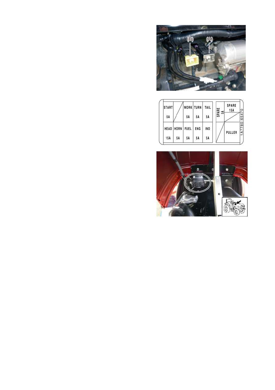
FUSE BOX
(1) The alternator fuse (60A) and main fuse (60A) are of
slow blow type. When any of these has been blown,
contact your local YANMAR dealer.
(A) Main fuse: 60A
(B) Alternator fuse: 60A
(2) The electrical fuses are in the engine compartment.
Use of fuse other than a correctly rated one way may
cause damage to the electrical system.
Replace the blow fuse with a new fuse of the same
amperage rating.
START : Starter motor
5A
WORK : Working light
5A
TURN : Turn signal light 5A
TAIL
: Tail light
5A
HEAD : Head light
15A
HORN : Horn
5A
FUEL : Fuel pump
5A
ENG : Timer relay
5A
IND
: Indicator light
5A