Kubota tractor (BX25DLB-AU, LA240A, LA240A, AU-SG, BT602). OPERATOR'S MANUAL - part 13
21
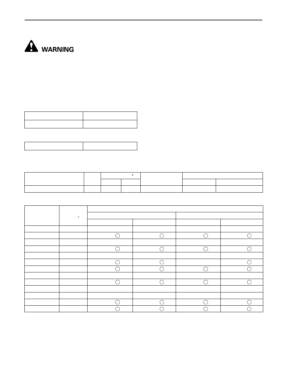
PRE-OPERATION CHECK OF THE LOADER
RATED OPERATING LOAD (SPILL GUARD MODEL ONLY)
To avoid personal injury or death:
A
Do not exceed ROL (Rated operation load).
A
Do not operate the loader without counter weight.
A
Do not exceed 10 km/h when travelling with load.
A
Use only tires approved by Kubota for loader use.
A
ROL is calculated with standard bucket. Optional attachments (4IN1 bucket etc.) will reduce ROL.
A
ROL is determined with the tractor static, on a hard level surface. Reduce load from the listed ROL if
operating on uneven or sloping terrain.
A
Remove the mid mount mower deck (if fitted) before operating the loader.
[With counter weight]
[With backhoe]
*Be sure to install the counter weight approved by
KUBOTA.
Rated operation load (ROL)
190 kg
Counter weight required
*170 kg
Rated operation load (ROL)
220 kg
Attachment
Width
(mm)
Capacity (m )
Attachment
Weight (kg)
Rated Operating Load (kg)
Heaped Struck
With Backhoe With counter Weight
LA240A AU-SG STD Bucket
1219
0.17
0.14
60
220
190
Material
DENSITY
(kg/m )
Standard Bucket
LA240A AU-SG with Backhoe
LA240A AU-SG with counter weight
Heaped Weight (kg) Struck Weight (kg) Heaped Weight (kg) Struck Weight (kg)
Blue Metal
1700
289 X
238 X
289 X
238 X
Clay Dry
1100
187
154
187
154
Clay Wet
1600
272 X
224 X
272 X
224 X
Earth Dry
1070
182
150
182
150
Earth Moist
1630
277 X
228 X
277 X
228 X
Earth Wet
1250
213
175
213 X
175
Fertilizer
1089
185
152
185
152
Gypsum
2547
433 X
357 X
433 X
357 X
Lime
849
144
119
144
119
Sand Dry
1720
292 X
241 X
292 X
241 X
Sand Wet
1900
323 X
266 X
323 X
266 X
Water
1000
170
140
170
140
Wheat
769
131
108
131
108