Snowmobile Arctic Cat 2-Stroke (2007 year). Manual - part 83
7-18
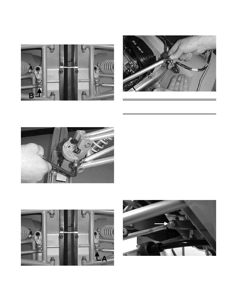
INSTALLING
1. Place the two tie rod ends into position on the
lower arm of the idler shaft. Secure with the Allen-
head cap screw (B) coated with green Loctite
#609. Tighten to specifications.
FC207B
2. Place the tie rod into position on the left-side steer-
ing arm. Secure with the Allen-head cap screw
coated with green Loctite #609. Tighten to specifi-
cations.
FC209
3. Place the two tie rod ends into position on the
lower arm of the steering shaft. Secure with the
Allen-head cap screw (A) coated with green Loc-
tite #609. Tighten to specifications.
FC207A
4. Place the tie rod into position on the right-side
spindle arm. Secure with the Allen-head cap screw
coated with green Loctite #609. Tighten to specifi-
cations.
5. Place the steering tie rod into position on the upper
arm of the steering shaft. Secure with the washer
and lock nut (threads coated with green Loctite
#609). Tighten lock nut to specifications.
FC206
Tie Rods
(F-Series)
REMOVING AND DISASSEMBLING
1. Remove the lock nut securing the tie rod to the
spindle.
NOTE: Note whether the tie rod is installed on the
top side or on the bottom side of the spindle arm
for installing purposes.
2. Turn the handlebar in the appropriate direction and
remove the cap screw and lock nut securing the tie
rod to the drag link.
NOTE: To aid in removing the tie rod cap screw
from the drag link, position the drag link so the cap
screw is aligned with the opening between the skid
plate and the suspension mounting bracket.
ZJ159A
3. Loosen the jam nuts securing the ball joints to the
tie rod; then remove the ball joints from the tie
rod.