Snowmobile Arctic Cat 2-Stroke (2007 year). Manual - part 81
7-10
3. Inspect the bearing halves, bearing caps, and
bearing housings for cracks or wear.
INSTALLING
1. Carefully install the steering post into the chas-
sis; then with the number of washers installed on
the stud of the post as noted during removing,
secure the steering post to the chassis with the
lock nut (threads coated with green Loctite
#609). Tighten to specifications.
ZJ157A
2. Install the steering tie rod to the steering post
and secure with the lock nut. Tighten to specifi-
cations.
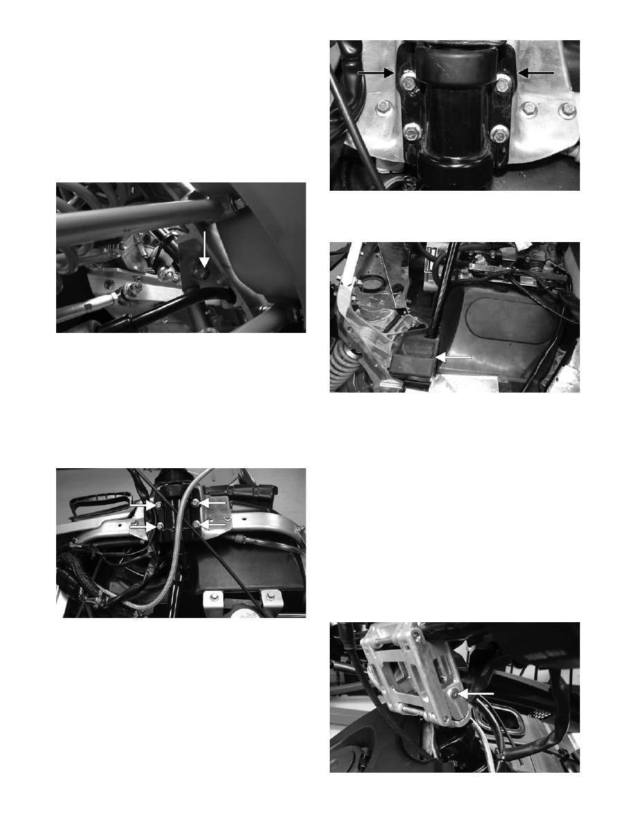
3. Secure the bearing bracket/steering post assem-
bly to the upper support plate with the bracket
plates and cap screws (coated with blue Loctite
#243). Tighten the cap screws to 1.1 kg-m (8 ft-
lb).
FS182A
NOTE: When installing the bracket plates, the
wider end of the plate must be directed up.
FS200A
4. Place the rubber exhaust bumper into position
on the air silencer.
FS203A
5. Place gaskets on the resonator and exhaust man-
ifold; then install the expansion chamber. Secure
the chamber to manifold and upper frame with
the springs.
6. On the standard model, place the handlebar/riser
assembly onto the steering post; then secure to
the steering post with the lower adjuster cap and
four Allen-head cap screws. Tighten cap screws
to specifications.
NOTE: Steps 7-11 are for the LXR/Sno Pro
models.
7. Install the handlebar riser block assembly to the
steering post; then secure the assembly with the
retainer and set screw.
ZJ154A