Snowmobile Polaris IQ (2007-2008 year). Manual - part 44
 

  Index      Snowmobiles / ATV     Snowmobile Polaris IQ - service manual 2007-2008 year


Search            


Content   ..  42  43  44  45   ..


Snowmobile Polaris IQ (2007-2008 year). Manual - part 44


6.6

Final Drive and Brakes

11. Reinstall the chain and upper / lower gears. Install the lower

gear washer with the beveled side facing out. Torque castle
nut and lower gear fastener to specifications.

12. Turn the chain tensioner bolt in until there is 0.25 in.

(6.35mm) deflection between the backside of the chain and
the chaincase.

13. Turn the tensioner bolt seal down into the chaincase.

Torque the tensioner bolt jam nut to specification.

14. Verify the cover seal is in good condition. Install the cover

and bracket. Torque fasteners to specification using a criss-
cross pattern.

15. Fill the chaincase with new chaincase oil until the level is

at the mid point of the sight glass.

16. Reinstall the exhaust silencer and door panel.

17. Reference the PVT System and Front and Rear

Suspensions chapters for idler shaft torque and PVT system
assembly information.

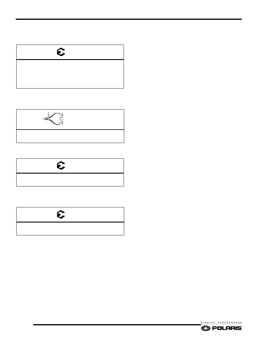
T 

Upper Gear Castle Nut

50 Ft.Lbs. (68 Nm)

(Back nut off only to align cotter pin holes with nut.) 

Lower Gear Fastener

19 Ft.Lbs. (26 Nm)

In. / mm. 

Drive Chain Deflection

0.25in. (6.35mm)

T 

Tensioner Jam Nut

21 Ft.lbs. (28 Nm)

T 

Chaincase Cover Fasteners

10 Ft.Lbs. (13 Nm)

6.7

Final Drive and Brakes

6

DRIVE TRAIN

Speedometer Cable Type Drive Train 

Assembly

NOTE:  Set driven clutch offset following procedure
in the PVT System Chapter.
Lubricate components as outlined in the Periodic
Maintenance Table.
Tighten chaincase mounting nuts using a criss-
cross pattern.
Install jackshaft seal sleeve with beveled edge
towards brake disc, then install o ring inside sleeve.

A

B

C

D

E

E

T 

A = Driven Clutch Fastener = 17 Ft.Lbs. (23 Nm)

B = Jackshaft Flange Nuts = 17 Ft.Lbs. (23 Nm)

C = Speedometer Housing Nuts = 17 Ft.Lbs. (23 Nm)

D = Driveshaft Housing Nuts = 17 Ft.Lbs. (23 Nm) 

E = Chaincase Mounting Nuts = 28 Ft.Lbs. (38 Nm)

CAUTION

Do not over-torque the chaincase mounting nuts.

6.8

Final Drive and Brakes

Electronic Speedometer Drive Train 

Assembly

NOTE:  Set driven clutch offset following procedure
in the PVT System Chapter.
Lubricate components as outlined in the Periodic
Maintenance Table.
Tighten chaincase mounting nuts using a criss-
cross pattern.
Install jackshaft seal sleeve with beveled edge
towards brake disc, then install o-ring inside sleeve.

DRIVEN CLUTCH

BELT

WASHERS

WASHERS

SPACER

FLANGE

FLANGE

JACKSHAFT

SNAP RING

BRAKE DISC

O RING

SEAL SLEEVE

SPEEDOMETER FLANGE

SPEEDOMETER SENSOR

DRIVESHAFT

CHAINCASE

A

B

C

D

E

E

F

G

T 

A = Driven Clutch Fastener = 17 Ft.Lbs. (23 Nm)

B = Jackshaft Flange Nuts = 17 Ft.Lbs. (23 Nm)

C = Speedometer Housing Nuts = 17 Ft.Lbs. (23 Nm)

D = Driveshaft Housing Nuts = 17 Ft.Lbs. (23 Nm)

E = Chaincase Mounting Nuts = 28 Ft.Lbs. (38 Nm)

F = Speedometer Sensor Screw = 5 Ft.Lbs. (7 Nm)

G = Speedometer Gear Screw = 15 Ft.Lbs. (11 Nm)

CAUTION

Do not over-torque the chaincase mounting nuts.

6.9

Final Drive and Brakes

6

Driveshaft Removal/Installation

1.

Remove the side panels.

2.

Remove the intake plenum. 

3.

Remove the drain plug and drain the chaincase fluid.

4.

Replace the chaincase drain plug and torque it to 8 ft-lb (11
N-m).

5.

Remove the chaincase cover.

6.

Loosen the tensioner.

7.

Remove the lower sprocket bolt and washer.

8.

Shut off the fuel valve if so equipped.

9.

Remove the exhaust system.

10. Remove the speedo drive pickup.

11. Remove the speedo drive housing.

12. Remove the rear skid.

13. With the sled over on its left side and the rear skid removed,

remove the drive shaft.

14. Assemble in reverse order

T 

Drain Plug: 8 ft-lb (11 N-m)


Content   ..  42  43  44  45   ..