Snowmobile Polaris PRO X (2003 year). Manual - part 43
CLUTCHING
4.40
Drive Belt Inspection
1.
Measure belt width and replace if worn severely.
Generally, belt should be replaced if clutches can no
longer be adjusted to provide proper belt deflection.
S
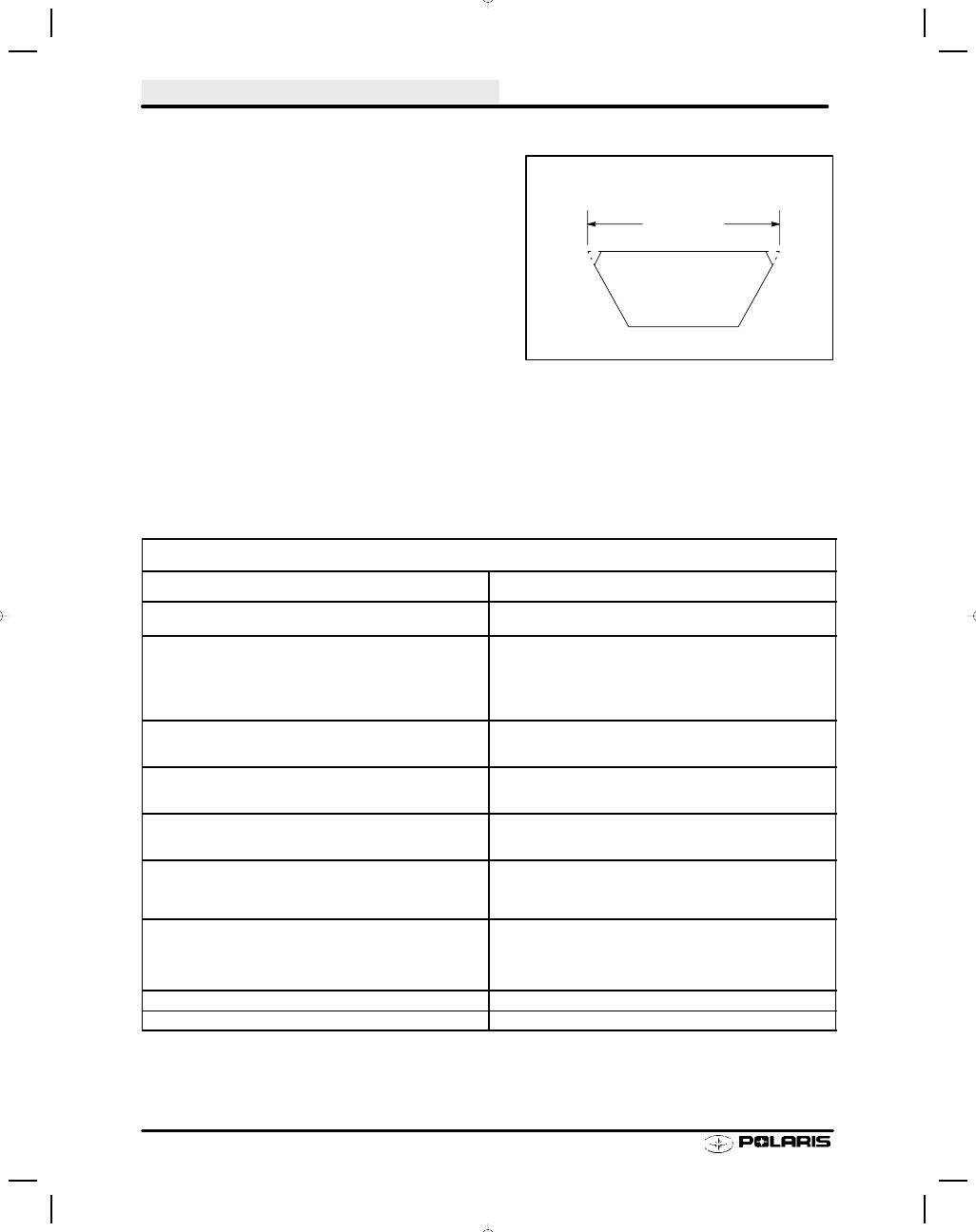
The top edges have been trimmed on some
drive belts. It will be necessary to project the
side profiles and measure from corner to corner.
S
Place a straight edge on each side of the drive
belt.
S
Place another straight edge on top of belt.
S
Measure the distance where the side straight
edges intersect the top, as shown in the illustra-
tion at right.
2.
Inspect belt for loose cords, missing cogs, cracks,
abrasions, thin spots, or excessive wear. Replace if
necessary.
3.
Inspect belt for hour glassing (extreme circular wear
in at least one spot and on both sides of the belt).
Hour glassing occurs when the drive train does not
move and the drive clutch engages the belt.
Belt Wear / Burn Diagnosis
Belt Wear / Burn Diagnosis
Possible Cause Of Wear Or Burning
Solution
Driving at or about engagement RPM for extended periods in all
types of conditions
Drive at higher RPM if possible. Gear the machine down. Make
sure belt deflection is at 1.25
s to achieve optimum starting ratio
Cold weather startups
Be patient. Warm up engine at least 5 minutes or until it readily
responds to throttle input. For the quickest most efficient driveaway
in extreme cold weather, take drive belt off machine and bring it in to
a warm environment. Break skis and track loose from the snow.
Engage throttle aggressively for short durations for initial cold drive-
away
Towing another machine at or about engagement RPM
When possible, do not go in deep snow when towing another ma-
chine. Use fast, effective throttle to engage the clutch. Not all ma-
chines are intended for pulling heavy loads or other machines.
Spinning track while vehicle is stuck (high RPM, low vehicle speed,
high ambient temp. Example: 8000 RPM, 10mph vehicle speed, 60
mph indicated on speedometer.
Lower the gear ratio. Remove windage plates from driven clutch. If
possible, move to better snow conditions and reduce RPM. Avoid
riding in very high ambient temperatures.
Ice and snow piled up between track and tunnel overnight or after
stopping for a long period of time (enough to re-freeze the snow).
Break loose snow and ice under tunnel. Allow longer than normal
warmup. Allow belt to warm sufficiently and increase grip ability on
clutch sheaves. Use fast, effective throttle when engaging clutch.
Poor running engine
(Bog, Miss, Backfire, etc.)
Maintain good state of tune including throttle and choke synchro-
nization. Check for fouled spark plug(s). Check for foreign material
in carbs. Make sure no water or ice in fuel tank, lines, or carbure-
tors.
Loading machine on trailer
Use caution when loading machine. Carbide skags may gouge into
trailer and prevent drive train from spinning freely. Use enough
speed to drive completely onto trailer. If machine cannot be driven
completely onto trailer, it may need to be pulled or pushed to avoid
belt wear / burning.
Clutch malfunction
Check for correct clutch components.
Slow, easy belt engagement -- easing on the throttle
Use fast, effective throttle to engage the clutch.
Projected Belt
Width