Snowmobile Polaris 600 Fusion (2006 year). Manual - part 10


  Index      Snowmobiles / ATV     Snowmobile Polaris 600 Fusion - service manual 2006 year


Search            


Content   ..  8  9  10  11   ..


Snowmobile Polaris 600 Fusion (2006 year). Manual - part 10


40

FEATURES

Instrumentation

MFD Digital Display Programs

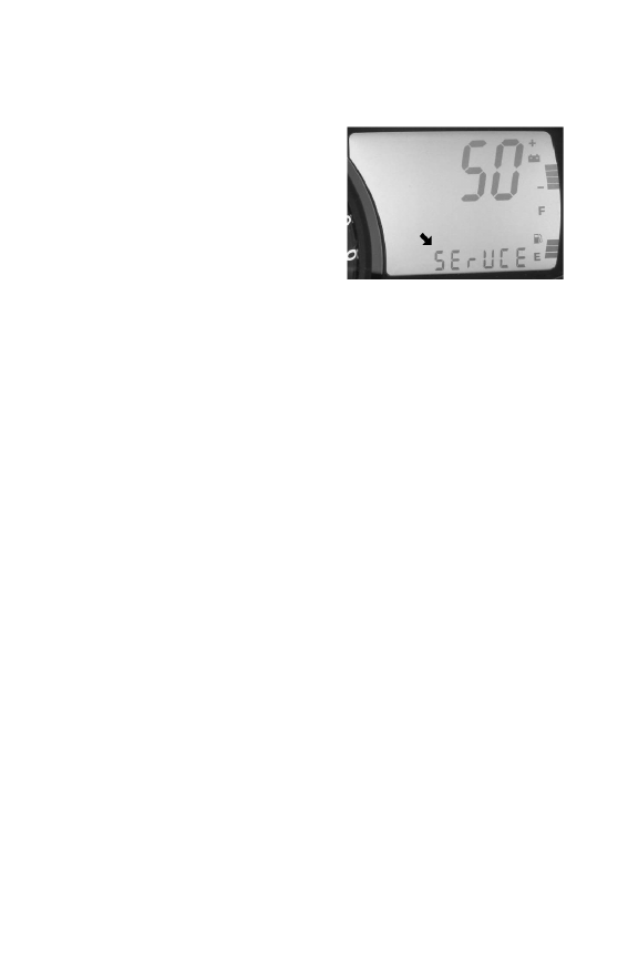
Service Interval Reminder
The gauge logs the number of engine 

hours between service reminders.  

When the logged hours reaches the 

designated service interval (set by the 

user), the gauge provides a reminder 

that service is due.  "SErVCE" will 

flash in the odometer area and "ENG" 

will flash in the icon area for five sec-

onds each time the vehicle is started until the service reminder is reset.

To reset the reminder at the existing interval:

1. Enter the service interval screen.
2. Press and hold the SET button for ten seconds, continuing to hold 

even after the display begins to flash.

3. When the display stops flashing, release the button.  The service 

interval has been reset.

To reset the reminder at a new interval:

1. Enter the service interval screen.
2. Press and hold the SET button for five seconds, until the hours 

begin to flash.

3. Immediately release the button.
4. Press the button again up to five times to advance the reminder in 

50-hour increments.

NOTE: The maximum interval is 250 hours.

To disable the service interval reminder, press the SET button once after 

reaching 250 hours on the display.  The gauge will display "OFF".

41

FEATURES

Instrumentation

MFD Battery Replacement

If the clock function of the MFD isn't 

working properly, replace the battery. 

Replacement batteries are available from 

your dealer.

1. Remove the plenum from the under-

side of the hood.

2. Locate the black battery compart-

ment.  It has a red wire and a brown 

wire with a white stripe.  It's located 

about three inches down the main 

harness from the point where the 

harness connects to the MFD.

3. Cut the plastic cable tie from the out-

side of the compartment.

4. Carefully cut the bottom of the com-

partment (opposite the wires) to separate the heat-sealed seams. 

Squeeze the corners of the compartment inward so the battery is 

visible.

NOTE: Note the orientation of the battery before removing it.  An incor-

rectly installed battery will not maintain the clock.

5. Using needle-nose pliers, grasp the battery and rotate it slightly so 

the leading edge of the battery is raised slightly away from the bat-

tery holder.  Pull the battery out gently.

NOTE: The battery will not come out of the holder unless the leading 

edge of the battery is raised.  Hold the battery compartment, 

not the wires, while removing the battery.  Pulling on the wires 

will separate them from the battery holder.

42

FEATURES

Instrumentation

MFD Battery Replacement

6. Install a new battery with fingers only.
7. Seal the end of the battery compartment using high strength double-

sided tape between the two compartment halves or high strength 

single-sided tape around the outside of the compartment.

8. Make sure the taped seam of the compartment faces the downward 

side of the wire harness.

9. Install a cable tie to secure the compartment to the wire harness in 

the same location where the previous cable tie was located.  Make 

sure the battery wires are not stretched tight.

Gauge Cleaning

1. Wipe the gauge face as needed using a clean cloth and a mild soap 

and water solution.  Wipe dry with clean, soft cloth.

2. Clean the back side of the gauge using a clean cloth and a mild soap 

and water solution.  Do not remove the electrical connectors or pro-

tective rubber boot.  Do not spray the back side of the gauge or the 

wire harness with a pressure washer or other water source.

CAUTION

To prevent damage to the lens, do not use alcohol for cleaning. Do not allow 

chemicals or sprays to come into contact with the lens.  Immediately clean off 

any gasoline that splashes on the gauge during refueling.

43

THE PERFECT FIT

IQ Front Suspension Adjustments

Independent Front Suspension (IFS)

Break in the suspension for about 150 miles (240 km) before making 

any fine-tuning adjustments. 

Settings will vary from rider to rider, depending on rider weight, vehicle 

speed, riding style, and trail conditions.  We recommend starting with 

factory settings and then customizing each adjustment individually to 

suit rider preference.  The machine should be methodically tested, one 

change at a time, under the same conditions (trail and snow conditions, 

vehicle speed, riding position, etc.) after each adjustment until the best 

ride is achieved. 

IFS Components
1. Skis
2. Front shocks and springs
3. Rod ends
4. A-arms

IFS Adjustment Options
• Front shock spring preload
• Optional springs
• Optional shock valving (if 

equipped with RydeFX 

shocks)

1

2

3

4


Content   ..  8  9  10  11   ..