Challenger Terra Gator 3244 Chassis. Manual - part 101
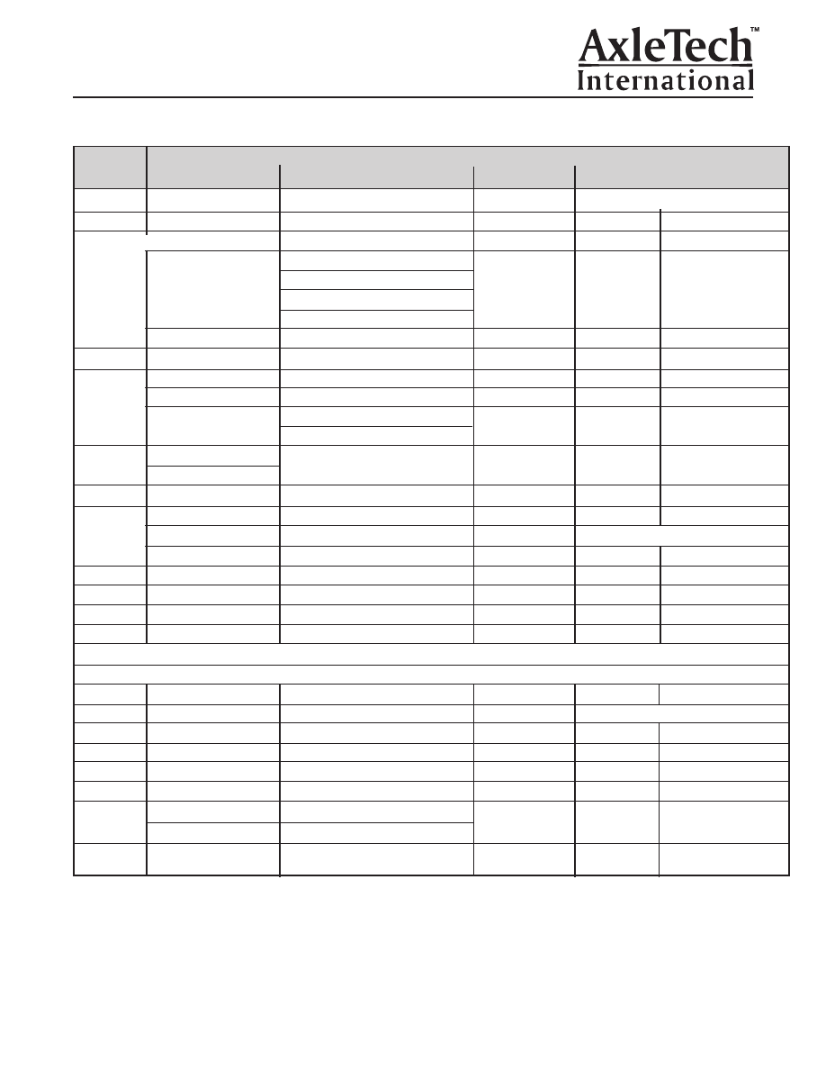
THREAD
TYPE
LOCATION
THREAD
TORQUE N•m (lb-ft)
SPEC
COMPOUND [1]
nominal
range
FASTENERS
capscrew L16 Allen-head Wheel Sup: Cover-Wheel Driver
medium-strength
38.3 (28.2)
33.5 (24.7) – 43.1 (31.8)
Wheel Sup: Lock Plate-Wheel Nut
Wheel Sup: Wheel Driver-Wheel Hub
M8x1.25
capscrew L25 Allen-head
Planet: Spring Hsg-Axle Hsg
medium-strength
38.3 (28.2)
33.5 (24.7) – 43.1 (31.8)
HDL: Inlet Port-Carrier Hsg
capscrew L30 Allen Head Carrier: Bearing Cap (Adj. Ring Lock)
medium strength
33.0 (24.3)
28 (20.7) - 38(28)
M10x1.5
setscrew L16 socket-head
Planet: Pinion Shaft-Spider
medium-strength
27.0 (19.9)
23.0 (16.9) - 31.0 (22.9)
capscrew L45 hex-head
Carrier Pinion Cage-Carrier Hsg
medium-strength
132 (97.4)
119 (87.7) - 145 (107)
capscrew L70 hex-head
Carrier: Diff. Case-Diff. Case
STF 02-452
143 (105.5)
130 (96) - 155 (114)
M12x1.75
Trunnion: Adapter-Axle Hsg
capscrew L80 Allen-head
Trunnion: Bracket-Trunnion Shaft
0il
119 (87.8)
107 (78.9) - 131 (96.6)
capscrew L50 hex-head
M16x2
capscrew L65 hex-head
Carrier: Carrier Hsg-Axle Hsg
high-strength
328 (241.9)
295 (217.6) - 361 (266.3)
M16x1.5
capscrew L62 hex-head
Carrier: Hypoid Gear-Diff. Case
medium-strength
350 (258)
315 (232) - 385 (284)
capscrew L140 hex-head Wheel Sup: Spindle-Axle Hsg
medium-strength
509 (375.4)
458 (337.8) - 560 (413.1)
M18x1.5
stud L170
Wheel Sup: Spindle-Axle Hsg
medium-strength
engage all threads
nut
Wheel Sup: Spindle-Axle Hsg
oil
412 (303.9)
371 (273.6) - 453 (334.1)
M20x2.5
capscrew L120 hex-head Carrier: Bearing Cap-Carrier Hsg
oil
485 (358)
430 (317) - 540 (398)
M22x1.5
nut-jam
Carrier: Hypoid Gear Thrust Screw
none
204 (150.5)
136 (100.3) - 272 (200.6)
M39x1.5
nut
Carrier: Yoke-Hypoid Pinion
oil
1,393 (1,027.5) 1,250 (922) - 1,535 (1132.2)
M150x2
nut
Wheel Sup: Wheel Brg-Spindle
oil
678 (500)
610 (449.9) - 746 (550.2)
PLUGS, FITTINGS
M12x1.5
fitting-Banjo
WDB:Banjo Fitting-Axle Hsg
oil
47.3 (34.9)
45.0 (33.2) - 49.5 (36.5)
M14x1.5
nut-fitting
WDB: Banjo Fitting-Tube
oil
finger tight + 1.5 turn
M22x1.5
port-inlet
WDB: Inlet Port-Axle Hsg
STF 02-452
37.8 (27.9)
34.0 (25.1) - 41.6 (30.7)
7/16”-20
screw-bleeder
WDB:Bleeder Screw-Axle Hsg
oil
23.5 (17)
20 (15) - 27 (20)
9/16”-18
fitting-Tee
WDB: Tee Fitting-Inlet Port
oil
35.7 (26.3)
34.0 (25.1) - 37.4 (27.6)
11/16”-16
nut-fitting
WDB: Tee Fitting-Tube
oil
42.0 (30.9)
40.0 (29.5) - 44.0 (32.5)
plug-fill
Hsg: Fill Plug
1 1/16”-12
plug-drain
Hsg: Drain Plug
oil
93 (68.6)
79 (58.3)
-
107 (78.9)
3/8-18 NPSF
breather
Top of Housing Breather
sealant-RTV or
28 Minimum
Permatex #51
[1] Thread compounds =
Medium-strength: Loctite #241/242/243, Three Bond #1334
High-strength: Loctite #271/273, Three Bond #1305
STF 02-452: Loctite 680
Sealants: Loctite Ultra Grey RTV, Permatex #51
Torque conversion factors
1N•m = 0.7376 lb-ft
1N•m = 10.20 kgf.cm
TORQUE TABLE
Section 6
Torque
Page 46