HUAWEI OptiX OSN 8800 T64/T32 Intelligent Optical Transport Platform. Product Overview - part 2

Table 2-1 Typical configurations of the N63B cabinet
Typ
Number of
PDU Model
Circuit
Maximum
Power
ical
Subracks and
Breaker a
Power
Consumpti
Con
Frames
Consumpti
on for the
figu
on of
Typical
rati
Integrated
Configurati
on
Equipment
on
b
1
2 x OptiX OSN
TN16
Eight 63 A
5400 W
< 4000 W
8800 T32
+ 1 x
circuit
DCM frame
breakers
2
1 x OptiX OSN
TN16
Four 63 A
5400 W
< 4000 W
8800 T32 + 2 x
and four 32
OptiX OSN 6800
A circuit
+ 2 x DCM
breakers
frame
3
1 x OptiX OSN
TN16
Eight 63 A
5000 W
< 4000 W
8800 T32 + 2 x
circuit
OptiX OSN
breakers
8800 T16 + 1 x
DCM frame
4
4 x OptiX OSN
TN16
Eight 63 A
5000 W
< 4000 W
8800 T16
+ 1 x
circuit
DCM frame
breakers
5
3 x OptiX OSN
TN16
Six 63 A and
5000 W
< 4000 W
8800 T16 +1 x
two 32 A
OptiX OSN 6800
circuit
+ 2 x DCM
breakers
frame
6
2 x OptiX OSN
TN16
Four 63 A
5000 W
< 4000 W
8800 T16 + 2 x
and four 32
OptiX OSN 6800
A circuit
+ 2 x DCM
breakers
frame
7
1 x OptiX OSN
TN16
Two 63 A
5000 W
< 4000 W
8800 T16 + 3 x
and six 32 A
OptiX OSN 6800
circuit
+ 2 x DCM
breakers
frame
8
4 x OptiX OSN
TN11
Four 63 A
4800 W
< 4000 W
6800 + 1 x DCM
circuit
frame
breakers
9
3 x OptiX OSN
TN11
Four 63 A
4800 W
< 4000 W
6800 + 2 x
circuit
CRPC frame + 3
breakers
x DCM frame
11

Typ
Number of
PDU Model
Circuit
Maximum
Power
ical
Subracks and
Breaker a
Power
Consumpti
Con
Frames
Consumpti
on for the
figu
on of
Typical
rati
Integrated
Configurati
on
Equipment
on
b
a: This column lists the number of circuit breakers required on the PDF.
b: The maximum power consumption of the integrated equipment refers to the maximum
power consumption of the cabinet or the maximum heat dissipation capacity of the
integrated equipment. The power consumption of the integrated equipment can not exceed
the maximum power consumption.
In the case of transmission equipment, power consumption is generally transformed into heat
consumption. Hence, heat consumption (BTU/h) and power consumption (W) can be converted to each
other in the formula: Heat consumption (BTU/h) = Power consumption (W) / 0.2931 (Wh).
Power consumption for the typical configuration refers to the average power consumption of the device
in normal scenarios. The maximum power consumption refers to the maximum power consumption of
the device under extreme conditions.
N66B Cabinet Structure
The N66B is an ETSI middle-column cabinet with 600 mm depth, complying with the ETS
300-119 standard.
The following subracks can be installed on the N66B cabinet: OptiX OSN 8800 T64, OptiX
OSN 8800 T32, OptiX OSN , and OptiX OSN 6800.
The N66B cabinet consists of the rack (main frame), open-close type front and rear doors, and
side panels at the left and right sides.
Cabinet doors and side panels can be disassembled. The front door and side panels have
grounding points. Keys to the front and rear doors of all N63B cabinets are the same.
Figure 2-4 shows the appearance of the N66B cabinet.
12

Figure 2-4 N66B cabinet appearance
Configuration of the Integrated N66B Cabinet
Typical configuration of the N66B cabinet involves settings of the following items: the
subrack type, the number of subracks, DCM and CRPC frames, and the PDU model.
Table 2-2 lists the typical configurations of the N66B cabinet.
13

Table 2-2 Typical configurations of the N66B cabinet
Typic
Number of
PDU
Circuit
Maximum
Power
al
Subracks and
Mode
Breaker a
Power
Consumptio
Confi
Frames
Consumptio
n for the
gurat
n of
Typical
ion
Integrated
Configuratio
Equipment b
n
1
1 x OptiX OSN
TN16
Sixteen 63
10800 W
< 6000 W
8800 T64 + 2 x
A circuit
OptiX OSN
breakers
8800 T32 + 2 x
DCM frame
2
1 x OptiX OSN
TN16
Eight 63 A
10800 W
< 6000 W
8800 T64 + 4 x
and eight
OptiX OSN
32 A circuit
6800 + 4 x DCM
breakers
frame
3
1 x OptiX OSN
TN16
Sixteen 63
10000 W
< 6000 W
8800 T64 + 4 x
A circuit
OptiX OSN
breakers
8800 T16 + 2 x
DCM frame
a: This column lists the number of circuit breakers required on the PDF.
b: The maximum power consumption of the integrated equipment refers to the maximum
power consumption of the cabinet or the maximum heat dissipation capacity of the
integrated equipment. The power consumption of the integrated equipment do not exceed
the maximum power consumption.
In the case of transmission equipment, power consumption is generally transformed into heat
consumption. Hence, heat consumption (BTU/h) and power consumption (W) can be converted to each
other in the formula: Heat consumption (BTU/h) = Power consumption (W) / 0.2931 (Wh).
Power consumption for the typical configuration refers to the average power consumption of the device
in normal scenarios. The maximum power consumption refers to the maximum power consumption of
the device under extreme conditions.
2.2.2 Subrack
The OptiX OSN 8800 T64 and OptiX OSN 8800 T32 take subracks as the basic working
units.
Subracks should be installed in the cabinet with 50 mm spacing above and below to allow
airing. The DC power distribution box in the cabinet supply power to the subrack, and the
subracks has independent power supply. The air circuit breaker has a rated value of 60 A.
Structure of the OptiX OSN 8800 T64
Subracks are the basic working units of the OptiX OSN 8800 T64. Each subrack has
independent power supply.
14
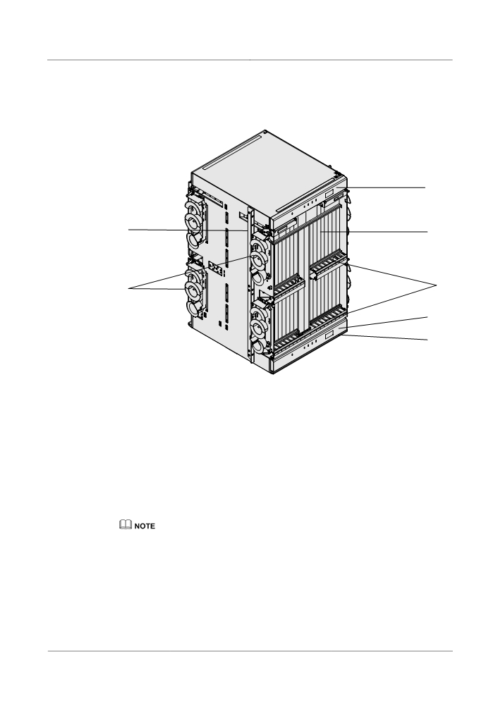
Figure 2-5 shows the structure of the OptiX OSN 8800 T64 subrack.
Table 2-3 describes the mechanical specifications of the 8800 T64 subrack.
Figure 2-5 OptiX OSN 8800 T64 subrack structure
3
6
1
5
2
3
4
1. Board area
2. Fiber cabling area
3. Fan tray assembly
4. Air filter
5. Fiber spool
6. Mounting ear
Board area: All the boards are installed in this area. 93 slots are available.
Fiber cabling area: Fiber jumpers from the ports on the front panel of each board are
routed to the fiber cabling area before being routed on a side of the open rack.
Fan tray assembly: Four fan tray assemblies are available for this subrack. Each fan tray
assembly contains three fans that provide ventilation and heat dissipation for the subrack.
The front panel of the fan tray assembly has four indicators that indicate fan status and
related information.
For detailed descriptions of the fan tray assembly, see Fan.
Air filter: It protects the subrack from dust in the air and requires periodic cleaning.
Fiber spool: Fixed fiber spools are on two sides of the subrack. Extra fibers are coiled in
the fiber spool on the open rack side before being routed to another subrack.
Mounting ears: The mounting ears attach the subrack in the cabinet.
15

Table 2-3 Mechanical specifications of the OptiX OSN 8800 T64
Item
Specification
Dimensions
498 mm (W) × 580 mm (D) × 900 mm (H)
(19.6 in. (W) × 22.8 in. (D) × 35.4 in. (H))
Weight (empty subracka)
65 kg (143 lb.)
a: An empty subrack means no boards are installed in the board area, and no fan tray
assembly or air filter is installed.
Structure of the OptiX OSN 8800 T32
Subracks are the basic working units of the OptiX OSN 8800 T32. Each subrack has
independent power supply.
Figure 2-6 shows the structure of the OptiX OSN 8800 T32 subrack.
Figure 2-6 OptiX OSN 8800 T32 subrack structure diagram
3
6
1
5
2
3
4
1. Board area
2. Fiber cabling area
3. Fan tray assembly
4. Air filter
5. Fiber spool
6. Mounting ear
Board area: All the boards are installed in this area. 50 slots are available.
16

Fiber cabling area: Fiber jumpers from the ports on the front panel of each board are
routed to the fiber cabling area before being routed on a side of the open rack.
Fan tray assembly: Fan tray assembly contains three fans that provide ventilation and
heat dissipation for the subrack. The front panel of the fan tray assembly has four
indicators that indicate subrack status.
For detailed descriptions of the fan tray assembly, see Fan.
Air filter: It protects the subrack from dust in the air and requires periodic cleaning.
Fiber spool: Fixed fiber spools are on two sides of the subrack. Extra fibers are coiled in
the fiber spool on the open rack side before being routed to another subrack.
Mounting ears: The mounting ears attach the subrack in the cabinet.
Table 2-4 Mechanical specifications of the OptiX OSN 8800 T32
Item
Specification
Dimensions
498 mm (W) × 295 mm (D) × 900 mm (H)
(19.6 in. (W) × 11.6 in. (D) × 35.4 in. (H))
Weight (empty subracka)
35 kg (77.1 lb.)
a: An empty subrack means no boards are installed in the board area, and no fan tray
assembly or air filter is installed.
Slot Distribution of the OptiX OSN 8800 T64
The board area and interface area of an OptiX OSN 8800 T64 subrack provide 93 slots.
Slots of the OptiX OSN 8800 T64 subrack are shown in Figure 2-7.
Figure 2-7 Slots of the OptiX OSN 8800 T64 subrack
Front
Back
IU91
IU93
A
A
U
SCC
STG
EF
U
SCC
STG
PIU
PIU
EFI2
X
IU
I1
IU
PIU
PIU
PIU
PIU
STI
X
IU
ATE
PIU
PIU
IU69
IU70
IU71
IU
73
IU74
IU75
IU
77
IU78
IU79
IU80
IU81
IU82
IU
84
IU85
IU86
IU87
IU88
IU89
72
76
83
IU
IU
IU
IU
IU
IU
IU
IU
IU
IU
IU
IU
IU
IU
IU
IU
IU
IU
IU
IU
IU
IU
IU
IU
IU
IU
IU
IU
IU
IU
IU
IU
19
20
21
22
23
24
25
26
27
28
29
30
31
32
33
34
53
54
55
56
57
58
59
60
61
62
63
64
65
66
67
68
IU
IU
IU
IU
9
10
43
44
IU
IU
IU
IU
IU
IU
IU
IU
IU
IU
IU
IU
IU
IU
IU
IU
IU
IU
IU
IU
IU
IU
IU
IU
IU
IU
IU
IU
IU
IU
IU
IU
1
2
3
4
5
6
7
8
11
12
13
14
15
16
17
18
35
36
37
38
39
40
41
42
45
46
47
48
49
50
51
52
IU90
IU92
17

:
houses service boards and supports service cross-connections.
IU9 and IU43 are reserved for the cross-connect board (XCT).
IU10 and IU44 are reserved for the cross-connect board (SXM/SXH).
IU73, IU77 and IU84 are reserved for future use.
The following table provides the slots for housing active and standby boards of the
subrack.
Board
Slots for Active and Standby Boards
PIU
IU69 & IU78, IU70 & IU79, IU80 & IU88, and IU81 &IU89
SCC
IU74 & IU85
STG
IU75 & IU86
SXM/SXH
IU10 & IU44
XCT
IU9 & IU43
Slot Distribution of the OptiX OSN 8800 T32
The board area and interface area of the OptiX OSN 8800 T32 subrack provide 50 slots.
Slots of the OptiX OSN 8800 T32 subrack are shown in Figure 2-8.
18

Figure 2-8 Slots of the OptiX OSN 8800 T32 subrack
IU51
AUX
STG
STG
EFI1
PIU
PIU
PIU
PIU
EFI2
STI
ATE
IU37
IU38
IU39
IU40
IU41
IU42
IU43
IU44
IU45
IU46
IU47
IU48
SCC
IU20
IU21
IU22
IU23
IU24
IU25
IU26
IU27
IU29
IU30
IU31
IU32
IU33
IU34
IU35
IU36
IU28
IU9
IU10
IU12
IU13
IU14
IU15
IU16
IU17
IU18
IU19
IU1
IU2
IU3
IU4
IU5
IU6
IU7
IU8
IU11
IU50
:
houses service boards and supports service cross-connections.
IU9 and IU10 are reserved for the cross-connect board (XCH/XCM).
IU43 is reserved for future use.
The following table provides the slots for housing active and standby boards of the
subrack.
Board
Slots for Active and Standby Boards
PIU
IU39 & IU45 and IU40 & IU46
SCC
IU28 & IU11
STG
IU42 & IU44
XCH/XCM
IU9 & IU10
19

2.2.3 Board
Function Boards
There are many types of functional boards, such as optical transponder boards and optical
multiplexer/demultiplexer boards.
The boards can be divided into several functional boards, as shown in Table 2-5.
Table 2-5 Functional boards
Functional boards
Boards
Optical transponder board
LDM, LDMD, LDMS, LDX, LEM24, LEX4, LOG,
LOM, LQM, LQMD, LQMS, LSQ, LSXL, LSXLR,
LSX, LSXR, LOA, LWXS, TMX
Tributary board
TOM, TQX, TDX, TOG, TOA, THA, TSXL
Line board
NS2, ND2, NS3, NQ2
PID board
NPO2, NPO2E, ENQ2, PQ2
OCS board
BPA, EGSH, SF64A, SLH41, SLO16, SLQ64, SF64,
SFD64, SL64, SLD64, SLQ16, EAS2
Cross-connect unit and system
AUX, SCC, XCH, XCMa, SXHb, SXMb, XCTb
and communication unit
Optical
FIU, D40, D40V, M40, M40V, ITL, SFIU
multiplexer/demultiplexer
board
Fixed optical add and drop
MR8V, CMR2, CMR4, DMR1, SBM2, MR8, MR2,
multiplexer board
MR4
Reconfigurable optical add and
ROAM, RDU9, RMU9, WSD9, WSM9, WSMD2,
drop multiplexer board
WSMD4, WSMD9
Optical amplifier board
CRPC, OAU1, OBU1, OBU2, HBA, DAS1
Optical supervisory channel
SC1, SC2, HSC1, ST2
(OSC) board
Clock board
STG
Optical protection board
DCP, OLP, SCS
Spectrum analyzer board
MCA4, MCA8, WMU, OPM8
Optical power and dispersion
DCU, GFU, TDC
equalizing board
Variable optical attenuator
VA1, VA4
board
Interface Board
ATE, EFI1, EFI2, STI
a: Only the OptiX OSN 8800 T32 supports the board.
20

Functional boards
Boards
b: Only the OptiX OSN 8800 T64 supports the board.
2.2.4 Small Form-Factor Pluggable (SFP) Module
There are four types of pluggable optical modules: the enhanced small form-factor pluggable
(eSFP), the small form-factor pluggable plus (SFP+), the tunable 10 Gbit/s small form-factor
pluggable (TXFP) and the 10 Gbit/s small form-factor pluggable (XFP). Because they are
pluggable, when you need to adjust the type of accessed services or replace a faulty optical
module, you can directly replace it without replacing its dominant board.
2.3 Software Architecture
The system software includes the board software, NE software and the network management
system.
2.3.1 Overview
The system software is of a modular design. Each module provides specific functions and
works with the other modules.
The entire software is distributed in three modules including board software, NE software and
NM system.
The system software is designed with a hierarchical structure. Each layer performs specific
functions and provides service for the upper layer.
The system software architecture is shown in Figure 2-9.
In the diagram, all the modules are NE software except the "Network Management System"
and "Board Software" modules.
21