Yamaha XV19SW(C), XV19W(C), XV19MW(C), XV19CTSW(C), XV19CTW(C), XV19CTMW(C). Service Manual - part 27
ELECTRICAL COMPONENTS
7-76
cal system, cause the lighting and ignition
systems to malfunction and could possibly
cause a fire.
▲▲▲
▲
▲ ▲▲▲
▲
▲ ▲▲▲
▲
▲ ▲▲▲
▲
▲ ▲▲▲
▲
▲ ▲▲▲
▲
▲▲▲
4. Install:
• Rider seat
Refer to “GENERAL CHASSIS” on page 4-1.
EAS28030
CHECKING AND CHARGING THE BATTERY
WARNING
EWA13290
Batteries generate explosive hydrogen gas
and contain electrolyte which is made of poi-
sonous and highly caustic sulfuric acid.
Therefore, always follow these preventive
measures:
• Wear protective eye gear when handling or
working near batteries.
• Charge batteries in a well-ventilated area.
• Keep batteries away from fire, sparks or
open flames (e.g., welding equipment,
lighted cigarettes).
• DO NOT SMOKE when charging or han-
dling batteries.
• KEEP BATTERIES AND ELECTROLYTE
OUT OF REACH OF CHILDREN.
• Avoid bodily contact with electrolyte as it
can cause severe burns or permanent eye
injury.
FIRST AID IN CASE OF BODILY CONTACT:
EXTERNAL
• Skin — Wash with water.
• Eyes — Flush with water for 15 minutes and
get immediate medical attention.
INTERNAL
• Drink large quantities of water or milk fol-
lowed with milk of magnesia, beaten egg or
vegetable oil. Get immediate medical atten-
tion.
CAUTION:
EC1D71020
• This is a sealed battery. Never remove the
sealing caps because the balance between
cells will not be maintained and battery per-
formance will deteriorate.
• Charging time, charging amperage and
charging voltage for an MF battery are dif-
ferent from those of conventional batteries.
The MF battery should be charged accord-
ing to the instructions for the charging
method. If the battery is overcharged, the
electrolyte level will drop considerably.
Therefore, take special care when charging
the battery.
NOTE:
Since MF batteries are sealed, it is not possible
to check the charge state of the battery by mea-
suring the specific gravity of the electrolyte.
Therefore, the charge of the battery has to be
checked by measuring the voltage at the battery
terminals.
1. Remove:
• Rider seat
Refer to “GENERAL CHASSIS” on page 4-1.
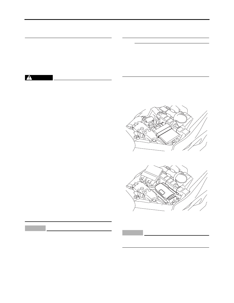
2. Remove:
• ECU band “1”
3. Remove:
• Coupler tray “1”
4. Disconnect:
• Battery leads
(from the battery terminals)
CAUTION:
ECA13640
First, disconnect the negative battery lead
“1”, and then positive battery lead “2”.
1
1