Yamaha XV19SW(C), XV19W(C), XV19MW(C), XV19CTSW(C), XV19CTW(C), XV19CTMW(C). Service Manual - part 26
FUEL INJECTION SYSTEM
7-60
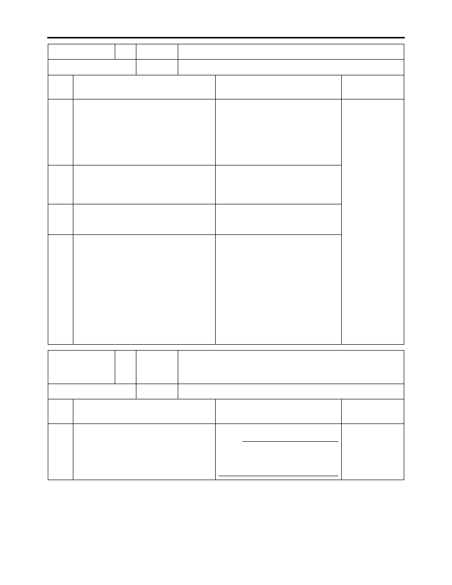
Fault code No.
46
Symptom Power supply to the fuel injection system is not normal.
Diagnostic code No.
—
—
Order Item/components and probable
cause
Check or maintenance job
Reinstatement
method
1
Connections
• Main wire harness ECU coupler
• Check the coupler for any pins
that may be pulled out.
• Check the locking condition of
the coupler.
• If there is a malfunction, repair it
and connect the coupler se-
curely.
Starting the en-
gine and oper-
ating it at idle.
2
Faulty battery.
• Replace or charge the battery
Refer to “CHECKING AND
CHARGING THE BATTERY” on
page 7-76.
3
Malfunction in rectifier/regulator
• Replace if defective.
Refer to “CHARGING SYS-
TEM” on page 7-13.
4
Open or short circuit in wire harness.
• Repair or replace if there is an
open or short circuit.
• Between battery and main fuse
(red–red)
• Between main fuse and main
switch
(red–red)
• Between main switch and igni-
tion fuse
(brown/blue–brown/blue)
• Between ignition fuse and ECU
(red/white–red/white)
Fault code No.
50
Symptom Faulty ECU memory. (When this malfunction is detected in
the ECU, the fault code number might not appear on the
meter.)
Diagnostic code No.
—
—
Order Item/components and probable
cause
Check or maintenance job
Reinstatement
method
1
Malfunction in ECU.
Replace the ECU.
NOTE:
Do not perform this procedure
with the main switch turned to
“ON”.
Turning the
main switch to
“ON”.