Yamaha XV19SW(C), XV19W(C), XV19MW(C), XV19CTSW(C), XV19CTW(C), XV19CTMW(C). Service Manual - part 15
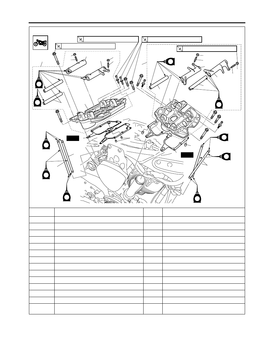
CAMSHAFTS
5-16
Removing the push rods and rocker arms
Order
Job/Parts to remove
Q’ty
Remarks
1
Rear rocker arm base assembly
1
2
Front rocker arm base assembly
1
3
Rocker arm base gasket
2
4
Dowel pin
4
5
Pull rod 1
3
l = 286.5 mm (11.280 in) pink painting
6
Pull rod 2
1
l = 288.5 mm (11.358 in) sky blue painting
7
Rocker arm shaft
4
8
Rocker arm 1
2
9
Rocker arm 2
2
10
Locknut
4
11
Adjusting screw
4
12
Rear rocker arm base
1
13
Front rocker arm base
1
For installation, reverse the removal proce-
dure.
E
E
E
E
E
E
E
E
E
10
11
8
10
11
9
7
6
5
12
3
4
4
10
11
8
7
10
11
9
7
5
4
3
New
New
1
2
13
R
10 Nm (1.0 m
•
kg, 7.2 ft
•
Ib)
T
R
24 Nm (2.4 m
•
kg, 17 ft
•
Ib)
T
R
20 Nm (2.0 m
•
kg, 14 ft
•
Ib)
E
R
24 Nm (2.4 m
•
kg, 17 ft
•
Ib)