Yamaha XV19SW(C), XV19W(C), XV19MW(C), XV19CTSW(C), XV19CTW(C), XV19CTMW(C). Service Manual - part 13
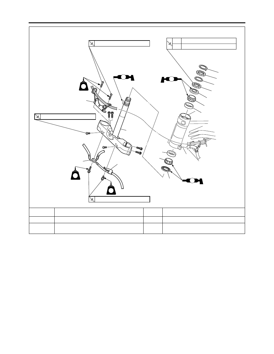
STEERING HEAD
4-70
13
Bearing outer race
2
For installation, reverse the removal proce-
dure.
Removing the lower bracket
Order
Job/Parts to remove
Q’ty
Remarks
8
1
3
2
12
11
13
13
10
9
7
6
5
4
LS
LS
LS
T
R
1st 52 Nm (5.2 m
•
kg, 37 ft
•
lb)
2nd 18 Nm (1.8 m
•
kg, 13 ft
•
Ib)
T
R
10 Nm (1.0 m
•
kg, 7.2 ft
•
Ib)
R
10 Nm (1.0 m
•
kg, 7.2 ft
•
Ib)
LT
LT
LT
T
R
16 Nm (1.6 m
•
kg, 11 ft
•
Ib)