Yamaha XVS1100 (L). Service Manual - part 12
Order
Job name / Part name
Q’ty
Remarks
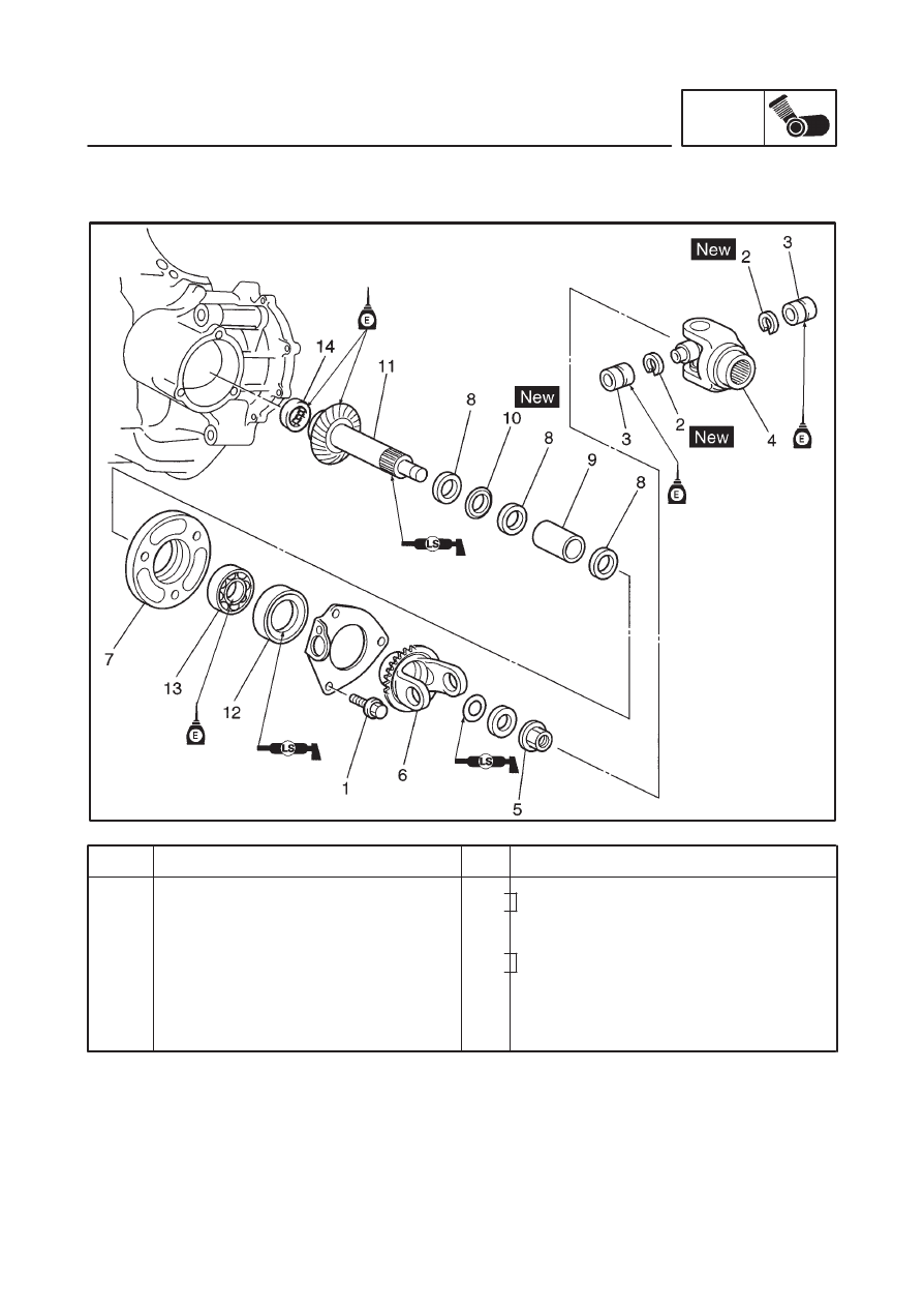
10
11
12
13
14
Collapsible collar
Middle driven shaft
Oil seal
Bearing
Bearing
1
1
1
1
For installation, reverse the removal
procedure.
Refer to “ASSEMBLING THE MIDDLE
DRIVEN SHAFT ASSEMBLY”.
Refer to “INSTALLING THE MIDDLE
GEAR ASSEMBLY AND ADJUSTING
THE BACKLASH”.
MIDDLE GEAR
ENG
4-74