Yamaha XVS1100 (L). Service Manual - part 10
4-42
CLUTCH
ENG
NOTE:
NOTE:
NOTE:
EAS00278
REMOVING THE CLUTCH
1. Straighten the lock washer tab.
2. Loosen:
clutch boss nut
1
While holding the clutch boss
2
with the clutch
holding tool
3
, loosen the clutch boss nut.
Clutch holding tool
90890-04086
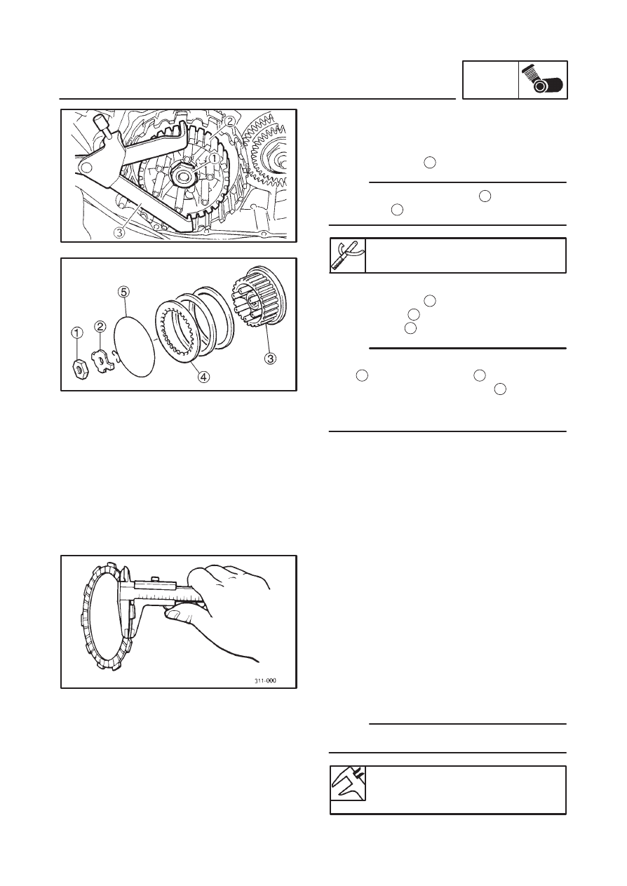
3. Remove:
clutch boss nut
1
lock washer
2
clutch boss
3
There is a built-in damper between the clutch
boss
3
and the clutch plate
4
. It is not neces-
sary to remove the wire circlip
5
and disas-
semble the built-in damper unless there is seri-
ous clutch chattering.
EAS00281
CHECKING THE FRICTION PLATES
The following procedure applies to all of the fric-
tion plates.
1. Check:
friction plate
Damage / wear
Replace the friction plates
as a set.
2. Measure:
friction plate thickness
Out of specification
Replace the friction
plates as a set.
Measure the friction plate at four places.
Friction plate thickness
2.9
3.1 mm
<Limit>: 2.8 mm