Yamaha YFM45FAR, YFM450FAR. Service Manual - part 24


  Index      Manuals     Yamaha YFM45FAR, YFM450FAR. Service Manual


Search            copyright infringement  


Content      ..     22      23      24      25     ..


Yamaha YFM45FAR, YFM450FAR. Service Manual - part 24


9 - 37

+

ELEC

SIGNAL SYSTEM

4.Horn does not sound. (for Europe and

Oceania)

CORRECT

1.Horn switch

Refer to “CHECKING THE SWITCH”.

INCORRECT

Replace horn switch.
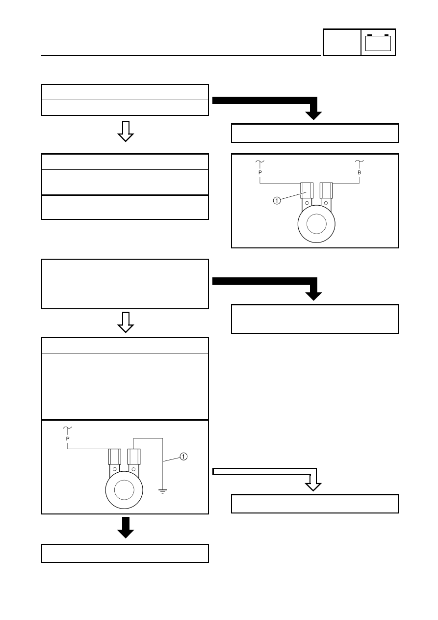
2.Voltage

Connect the pocket tester (DC 20 V) to the
horn connector at the horn terminal.

Tester (+) lead 

 Pink lead 

1


Tester (–) lead 

 Frame ground

MEETS
SPECIFICATION

HORN IS NOT
SOUNDED

Turn the main switch to “ON”.

Push the horn switch.

Check for voltage (12 V) on the “Pink” lead
at the horn terminal.

3.Horn

Disconnect the black lead at the horn
terminal.

Connect a jumper lead 

1

 to the horn

terminal and ground the jumper lead.

Turn the main switch to “ON”.

Push the horn switch.

Adjust or replace horn.

OUT OF SPECIFICATION

The wiring circuit from the main switch to the
bulb socket connector is faulty, repair it.

HORN IS SOUNDED

Horn is good.

9 - 38

+

ELEC

COOLING SYSTEM

COOLING SYSTEM

CIRCUIT DIAGRAM

W

/

B

B

B

/

R

B

/

R

B

W

/

B

C

D

OB

BO

LB

BL

YB

r

BB

B

/

Y

B

BB

(GRA

Y)

(GRA

Y)

D

WIRE HARNESS

SUB-WIRE 

HARNESS 4

Br

Sb

L

/

B

R

/

B

Br

/

B

B

/

Y

L

/

B

Sb

Br

B

/

Y

Br

/

B

R

/

B

Br

Y

L

L

/

B

GB

LY

R

/

Y

BG

L

/

B

WS

b

G

/

L

L

/

WB

/

RW

/

L

G

/

L

Sb

W

W

/

LB

/

RL

/

W

W

/

R

Sb

L

/

WG

/

W

Sb

W

/

R

G

/

WL

/

W

W

/

B

L

/

Y

Br

W

/

R

L

/

Y

W

/

B

W

/

R

Br

W

/

G

R

W

/

RW

/

G

R

W

/

G

W

/

L

W

/

R

RB

r

R

Br

/

L

Br

R

Br

/

L

R

L

/

GL

/

R

L

/

B

Sb

L

/

RL

/

G

Sb

L

/

B

R

L

/

WL

/

B

R

/

BL

/

W

OB

B

/

Y

R

W

/

RW

/

G

W

Y

/

B

B

/

RG

/

L

G

/

WW

/

B

Sb

G

/

R

(BLA

CK)

(BLA

CK)

(BLA

CK)

C

WIRE HARNESS

SUB-WIRE 

HARNESS 3

B

WIRE HARNESS

SUB-WIRE 

HARNESS 2

A

WIRE HARNESS

SUB-WIRE 

HARNESS 1

(BLA

CK)

(BLA

CK)

(BLA

CK)

(GRA

Y)

(GRA

Y)

(GRA

Y)

(GRA

Y)

(BLA

CK)

(BLA

CK)

Gy

G

/

R

Br

B

G

/

R

Gy

BB

r

(GRA

Y)

(GRA

Y)

W

WW

W

WW

OFF

ON

OFF

2WD

4WD

LOCK

W

/

G

Br

/

L

R

/

G

L

/

B

G

/

W

G

/

W

L

/

W

Br

Br

W

/

R

W

/

G

R

W

/

G

W

/

R

L

/

W

L

/

Y

R

/

B

G

/

W

Y

/

B

G

/

R

Sb

G

/

L

W

/

B

B

/

R

B

/

Y

B

/

Y

L

/

Y

R

/

G

Br

/

R

B

/

R

W

/

B

G

/

L

G

/

R

W

/

L

W

/

L

R

Br

Sb

O

C

B

O

B

W

W

B

B

B

W

B

W

W

W

W

W

W

R

R

R

R

B

WW

W

R

B

B

PUSH

_

R

R

B

B

B

B

B

B

R

R

R

D

W

/

R

W

/

R

D

L

/

W

B

/

R

B

/

R

L

/

W

D

A

Br

/

B

Br

/

B

Br

/

B

B

B

W

/

B

W

/

B

W

/

B

A

Sb

Sb

O

/

R

P

B

/

W

L

/

Y

W

B

G

/

R

R

/

G

B

G

/

RR

/

G

B

Y

G

B

YG

B

YG

B

B

/

Y

Br

/

R

Br

/

R

L

/

R

B

(BLACK)

Br

/

B

Br

/

R

Br

/

R

L

/

G

B

(BLACK)

Br

/

R

L

/

R

B

/

Y

Br

/

R

B

Br

/

R

L

/

G

Br

/

B

B

B

B

B

B

Br

Sb

L

/

B

L

/

G

Br

B

/

Y

Sb

L

/

B

B

/

Y

L

/

R

Y

/

B

Br

/

R

L

/

R

Gy

Gy

G

/

R

Br

/

B

W

/

B

B

B

/

YB

/

R

B

L

/

B

Sb

Br

B

B

B

B

A

Y

/

B

Gy

Br

/

R

L

/

R

Br

/

L

Br

/

R

Br

/

L

L

/

B

R

/

B

Br

/

L

R

/

W

R

/

W

Br

/

L

R

/

Y

Br

/

L

Br

R

/

B

R

/

B

R

/

Y

P

B

B

B

G
Y

G
Y

B

L

L

L

PUSH

_

Br

B

B

P

(BLACK)

(BLACK)

R

/

B

R

/

W

R

/

B

R

/

W

B

G
Y

B

L
Y

Y

G

B

(DARK GRAY)

(BLACK)

(BLACK)

L

R

/

B

Br

Y

YB

r

BB

(BLACK)

(BLACK)

Br

Y

Br

B

Br

B

1

2

3

4

5

6

7

8

9

0

A

B

C

D

E

F

G

HI

J

K

L

M

O

P

Q

R

ST

U

V

W

Y

\

]

b

d

e

i

g

j

k

h

b

^a

X

Z

[

c

f

N

3

Main s

witc

h

5

Battery

6

Main

 fu

se

c

Circuit

 br

eaker

 (f

an

 mo

to

r)

d

Thermo s

witch 2

e

Fan

 m

o

tor

9 - 39

+

ELEC

COOLING SYSTEM

TROUBLESHOOTING 

Procedure

Check:
1.Fuse (main)
2.Battery
3.Main switch
4.Fan motor
5.Circuit breaker (fan motor)

IF THE FAN MOTOR DOES NOT MOVE:

6.Thermo switch 2
7.Wiring connection

(the entire cooling system)

NOTE:

Remove the following part(s) before
troubleshooting.

1)Seat
2)Front carrier
3)Front fender

Use the following special tool(s) for
troubleshooting.

Pocket tester:

P/N. YU-03112, 90890-03112

EB802011

CONTINUITY

1.Fuse (main)

Refer to “CHECKING THE SWITCH”.

NO CONTINUITY

Replace the fuse.

EB802012

CORRECT

2.Battery

Check the battery condition.
Refer to “CHECKING THE BATTERY” in
CHAPTER 3.

Open-circuit voltage:

12.8 V or more at 20 °C (68 °F)

INCORRECT

Clean the battery terminals.

Recharge or replace the battery.

CORRECT

3.Main switch

Refer to “CHECKING THE SWITCH”.

*

INCORRECT 

Replace the main switch.

9 - 40

+

ELEC

COOLING SYSTEM

C0NTINUITY

TURNS

4.Fan motor

Disconnect the fan motor coupler.

Connect the battery (12 V) as shown.

Battery (+) lead 

 Blue terminal 

1


Battery (–) lead 

 Black terminal 

2


Check the operation of the fan motor.

*

DOES NOT TURN

Replace the fan motor.

MEETS
SPECIFICATION

5.Circuit breaker (fan motor)

Remove the circuit breaker from the wire
harness.

Connect the pocket tester (


×

 1) to the

circuit breaker.

Circuit breaker resistance:

Zero 

 at 20 °C (68 °F)

*

OUT OF SPECIFICATION

Replace the circuit breaker.

9 - 41

+

ELEC

COOLING SYSTEM

C0NTINUITY

GOOD
CONDITION

6.Thermo switch 2

Remove the thermo switch 2 from the
radiator.

Connect the pocket tester (


×

 10) to the

thermo switch 2 

1

.

Immerse the thermo switch 2 in coolant 

2

.

Check the thermo switch 2 for continuity.
While heating the coolant use a
thermometer 

3

 to record the

temperatures.

Test 
step

Coolant temperature

Continuity

Thermo switch 2

1

Less than 86 ± 3 °C

(186.8 ± 5.4 °F)

NO

2

More than 86 ± 3 °C

(186.8 ± 5.4 °F)

YES

3

More than 80 ± 3 °C

(176 ± 5.4 °F)

YES

4

Less than 80 ± 3 °C

(176 ± 5.4 °F)

NO

Test steps 1 & 2: Heating phase
Test steps 3 & 4: Cooling phase

È

The thermo switch 2 circuit is open and the
radiator fan is off.

É

The thermo switch 2 circuit is closed and the
radiator fan is on.

WARNING

Handle the thermo switch 2 with special
care.
Never subject it to a strong shock or
allow it to be dropped. Should it be
dropped, it must be replaced.

T


R

.

.

Thermo switch 2:

28 Nm (2.8 m • kg, 20 ft • lb)
Three bond sealock

®

 #10

*

*

É

È

80 ± 3 ˚C

(176 ± 5.4 ˚F)

86 ± 3 ˚C

(186.8 ± 5.4 ˚F)

BAD CONDITION

Replace the thermo switch 2.

9 - 42

+

ELEC

COOLING SYSTEM

C0NTINUITY

EB803028

CORRECT

7.Wiring connection

Check the connections of the entire starting
system.
Refer to “CIRCUIT DIAGRAM”.

This circuit is not faulty.

*

POOR CONNECTION

Properly connect the cooling system.

9 - 43

+

ELEC

2WD/4WD SELECTING SYSTEM

2WD/4WD SELECTING SYSTEM

CIRCUIT DIAGRAM

W

/

B

B

B

/

R

B

/

R

B

W

/

B

C

D

OB

BO

LB

BL

YB

r

BB

B

/

Y

B

BB

(GRA

Y)

(GRA

Y)

D

WIRE HARNESS

SUB-WIRE 

HARNESS 4

Br

Sb

L

/

B

R

/

B

Br

/

B

B

/

Y

L

/

B

Sb

Br

B

/

Y

Br

/

B

R

/

B

Br

Y

L

L

/

B

GB

LY

R

/

Y

BG

L

/

B

WS

b

G

/

L

L

/

WB

/

RW

/

L

G

/

L

Sb

W

W

/

LB

/

RL

/

W

W

/

R

Sb

L

/

WG

/

W

Sb

W

/

R

G

/

WL

/

W

W

/

B

L

/

Y

Br

W

/

R

L

/

Y

W

/

B

W

/

R

Br

W

/

G

R

W

/

RW

/

G

R

W

/

G

W

/

L

W

/

R

RB

r

R

Br

/

L

Br

R

Br

/

L

R

L

/

GL

/

R

L

/

B

Sb

L

/

RL

/

G

Sb

L

/

B

R

L

/

WL

/

B

R

/

BL

/

W

OB

B

/

Y

R

W

/

RW

/

G

W

Y

/

B

B

/

RG

/

L

G

/

WW

/

B

Sb

G

/

R

(BLA

CK)

(BLA

CK)

(BLA

CK)

C

WIRE HARNESS

SUB-WIRE 

HARNESS 3

B

WIRE HARNESS

SUB-WIRE 

HARNESS 2

A

WIRE HARNESS

SUB-WIRE 

HARNESS 1

(BLA

CK)

(BLA

CK)

(BLA

CK)

(GRA

Y)

(GRA

Y)

(GRA

Y)

(GRA

Y)

(BLA

CK)

(BLA

CK)

Gy

G

/

R

Br

B

G

/

R

Gy

BB

r

(GRA

Y)

(GRA

Y)

W

WW

W

WW

OFF

ON

OFF

2WD

4WD

LOCK

W

/

G

Br

/

L

R

/

G

L

/

B

G

/

W

G

/

W

L

/

W

Br

Br

W

/

R

W

/

G

R

W

/

G

W

/

R

L

/

W

L

/

Y

R

/

B

G

/

W

Y

/

B

G

/

R

Sb

G

/

L

W

/

B

B

/

R

B

/

Y

B

/

Y

L

/

Y

R

/

G

Br

/

R

B

/

R

W

/

B

G

/

L

G

/

R

W

/

L

W

/

L

R

Br

Sb

O

C

B

O

B

W

W

B

B

B

W

B

W

W

W

W

W

W

R

R

R

R

B

WW

W

R

B

B

PUSH

_

R

R

B

B

B

B

B

B

R

R

R

D

W

/

R

W

/

R

D

L

/

W

B

/

R

B

/

R

L

/

W

D

A

Br

/

B

Br

/

B

Br

/

B

B

B

W

/

B

W

/

B

W

/

B

A

Sb

Sb

O

/

R

P

B

/

W

L

/

Y

W

B

G

/

R

R

/

G

B

G

/

RR

/

G

B

Y

G

B

YG

B

YG

B

B

/

Y

Br

/

R

Br

/

R

L

/

R

B

(BLACK)

Br

/

B

Br

/

R

Br

/

R

L

/

G

B

(BLACK)

Br

/

R

L

/

R

B

/

Y

Br

/

R

B

Br

/

R

L

/

G

Br

/

B

B

B

B

B

B

Br

Sb

L

/

B

L

/

G

Br

B

/

Y

Sb

L

/

B

B

/

Y

L

/

R

Y

/

B

Br

/

R

L

/

R

Gy

Gy

G

/

R

Br

/

B

W

/

B

B

B

/

YB

/

R

B

L

/

B

Sb

Br

B

B

B

B

A

Y

/

B

Gy

Br

/

R

L

/

R

Br

/

L

Br

/

R

Br

/

L

L

/

B

R

/

B

Br

/

L

R

/

W

R

/

W

Br

/

L

R

/

Y

Br

/

L

Br

R

/

B

R

/

B

R

/

Y

P

B

B

B

G
Y

G
Y

B

L

L

L

PUSH

_

Br

B

B

P

(BLACK)

(BLACK)

R

/

B

R

/

W

R

/

B

R

/

W

B

G
Y

B

L
Y

Y

G

B

(DARK GRAY)

(BLACK)

(BLACK)

L

R

/

B

Br

Y

YB

r

BB

(BLACK)

(BLACK)

Br

Y

Br

B

Br

B

1

2

3

4

5

6

7

8

9

0

A

B

C

D

E

F

G

HI

J

K

L

M

O

P

Q

R

ST

U

V

W

Y

\

]

b

d

e

i

g

j

k

h

b

^a

X

Z

[

c

f

N

3

Main switch

5

Battery

6

Main fuse

0

CDI unit

R

Four-wheel drive fuse

S

Four-wheel drive relay 1

T

Four-wheel drive relay 2

U

Four-wheel drive relay 3

V

On-command four-wheel drive switch and 
differential gear lock switch

W

Gear motor

9 - 44

+

ELEC

2WD/4WD SELECTING SYSTEM

EB803020

TROUBLESHOOTING

Procedure

Check:
1.Fuse (main, four-wheel drive)
2.Battery
3.Main switch
4.Four-wheel drive relay 1
5.Four-wheel drive relay 2
6.Four-wheel drive relay 3

IF THE GEAR MOTOR FAILS TO OPERATE:

7.On-command four-wheel drive switch and 

differential gear lock switch

8.Gear motor
9.Wiring connections 

(the entire 2WD/4WD selecting system)

NOTE:

Remove the following part(s) before
troubleshooting:

1)Seat
2)Front carrier
3)Front fender

Use the following special tool(s) for
troubleshooting.

Pocket tester:

P/N. YU-03112, 90890-03112

EB802011

CONTINUITY

1.Fuse (main, four-wheel drive)

Refer to “CHECKING THE SWITCH”.

NO CONTINUITY

Replace the fuse.

EB802012

CORRECT

2.Battery

Check the battery condition.
Refer to “CHECKING THE BATTERY” in
CHAPTER 3.

Open-circuit voltage:

12.8 V or more at 20 °C (68 °F)

INCORRECT

Clean the battery terminals.

Recharge or replace the battery.

CORRECT

3.Main switch

Refer to “CHECKING THE SWITCH”.

*

INCORRECT

Replace the main switch.

9 - 45

+

ELEC

2WD/4WD SELECTING SYSTEM

C0NTINUITY

CONTINUITY

4.Four-wheel drive relay 1

Remove the four-wheel drive relay 1 from
the wire harness.

Connect the pocket tester (


×

 1) and the

battery (12 V) to the four-wheel drive relay
1 terminals.

Tester (+) lead 


Brown/Black terminal 

1

Tester (–) lead 

 Black terminal 

2


Battery (+) terminal 


Brown/Red terminal 

3

Battery (–) terminal 


Blue/Green terminal 

4

Tester (+) lead 


Brown/Black terminal 

1

Tester (–) lead 

 Brown/Red terminal 

5


Check the four-wheel drive relay 1 for
continuity.

*

NO CONTINUITY

Replace the four-wheel drive relay 1.

CONTINUITY

5.Four-wheel drive relay 2

Remove the four-wheel drive relay 2 from
the wire harness.

Connect the pocket tester (


×

 1) and the

battery (12 V) to the four-wheel drive relay
2 terminals.

Tester (+) lead 


Black/Yellow terminal 

1

Tester (–) lead 

 Black terminal 

2


Battery (+) terminal 


Brown/Red terminal 

3

Battery (–) terminal 


Blue/Red terminal 

4

Tester (+) lead 


Black/Yellow terminal 

1

Tester (–) lead 

 Brown/Red terminal 

5


Check the four-wheel drive relay 2 for
continuity.

*

NO CONTINUITY

Replace the four-wheel drive relay 2.

9 - 46

+

ELEC

2WD/4WD SELECTING SYSTEM

C0NTINUITY

CONTINUITY

6.Four-wheel drive relay 3

Remove the four-wheel drive relay 3 from
the wire harness.

Connect the pocket tester (


×

 1) and the

battery (12 V) to the four-wheel drive relay
3 terminals.

Tester (+) lead 


Brown/Red terminal 

1

Tester (–) lead 


Yellow/Black terminal 

2

Battery (+) terminal 


Brown/Red terminal 

1

Battery (–) terminal 


Yellow/Black terminal 

2

Tester (+) lead 

 Blue/Red terminal 

3


Tester (–) lead 

 Gray terminal 

4


Check the four-wheel drive relay 3 for
continuity.

*

NO CONTINUITY

Replace the four-wheel drive relay 3.

CORRECT

7.On-command four-wheel drive switch and

differential gear lock switch

Refer to “CHECKING THE SWITCH”.

*

INCORRECT 

Replace the on-command four-wheel drive
switch and differential gear lock switch.

9 - 47

+

ELEC

2WD/4WD SELECTING SYSTEM

C0NTINUITY

CORRECT

8.Gear motor

Disconnect the gear motor coupler.

Remove the gear motor from the
differential gear case.
Refer to “FRONT CONSTANT VELOCITY
JOINTS AND DIFFERENTIAL GEAR” in
CHAPTER 7.

Connect two C size batteries to the gear
motor terminals 

1

 (as shown illustrations).

È

Check that the pinion gear 

2

 turns

counterclockwise.

É

Check that the pinion gear 

2

 turns clockwise.

Make sure that the drive gear (shift fork
sliding gear) operates correctly.

NOTE:

When installing the differential gear case in
the gear motor, refer to “FRONT CONSTANT
VELOCITY JOINTS AND DIFFERENTIAL
GEAR” in CHAPTER 7.

*

INCORRECT

Replace the gear motor.

EB803028

CORRECT

9.Wiring connection

Check the connections of the entire 2WD/
4WD selecting system.
Refer to “CIRCUIT DIAGRAM”.

Replace the CDI unit.

POOR CONNECTION

Properly connect the 2WD/4WD selecting
system.

È

É

TRBL

SHTG

10

TRBL

SHTG

CHAPTER 10.

TROUBLESHOOTING

STARTING FAILURE/HARD STARTING 

.................................................. 10-1

FUEL SYSTEM  ................................................................................... 10-1
ELECTRICAL SYSTEM  ...................................................................... 10-1
COMPRESSION SYSTEM .................................................................. 10-2

POOR IDLE SPEED PERFORMANCE 

...................................................... 10-2

POOR IDLE SPEED PERFORMANCE ............................................... 10-2

POOR MEDIUM AND HIGH-SPEED PERFORMANCE 

............................. 10-2

POOR MEDIUM AND HIGH-SPEED PERFORMANCE  ..................... 10-2

FAULTY DRIVE TRAIN 

.............................................................................. 10-3

FAULTY GEAR SHIFTING 

......................................................................... 10-4

HARD SHIFTING  ................................................................................ 10-4
SHIFT LEVER DOES NOT MOVE ...................................................... 10-4
JUMPS OUT OF GEAR  ...................................................................... 10-4

FAULTY CLUTCH PERFORMANCE 

......................................................... 10-4

ENGINE OPERATES BUT MACHINE WILL NOT MOVE ................... 10-4
CLUTCH SLIPPING  ............................................................................ 10-4
POOR STARTING PERFORMANCE .................................................. 10-4
POOR SPEED PERFORMANCE ........................................................ 10-5

OVERHEATING 

.......................................................................................... 10-5

OVERHEATING .................................................................................. 10-5

FAULTY BRAKE 

........................................................................................ 10-5

POOR BRAKING EFFECT .................................................................. 10-5

SHOCK ABSORBER MALFUNCTION 

...................................................... 10-6

MALFUNCTION .................................................................................. 10-6

UNSTABLE HANDLING 

............................................................................. 10-6

UNSTABLE HANDLING ...................................................................... 10-6

LIGHTING SYSTEM 

................................................................................... 10-6

HEADLIGHT DARK ............................................................................. 10-6
BULB BURNT OUT  ............................................................................. 10-6

TRBL

SHTG

10 - 1

TRBL

SHTG

STARTING FAILURE/HARD STARTING

TROUBLESHOOTING

NOTE:

The following troubleshooting does not cover all the possible causes of trouble. It should be helpful,
however, as a guide to troubleshooting. Refer to the relative procedure in this manual for checking,
adjusting and replacing of parts.

STARTING FAILURE/HARD STARTING

FUEL SYSTEM 
Fuel tank

Empty

Clogged fuel filter

Clogged fuel strainer

Clogged fuel breather hose

Deteriorated or contaminated fuel

Fuel cock

Clogged fuel hose

ELECTRICAL SYSTEM 
Spark plug

Improper plug gap

Worn electrodes

Wire between terminals broken

Improper heat range

Faulty spark plug cap

Ignition coil

Broken or shorted primary/secondary

Faulty spark plug lead

Broken body

CDI system

Faulty CDI unit

Faulty pickup coil

Faulty charging/rotor rotation direction coil

Broken woodruff key

Carburetor

Deteriorated or contaminated fuel

Clogged pilot jet

Clogged pilot air passage

Sucked-in air

Deformed float

Worn needle valve

Improperly sealed valve seat

Improperly adjusted fuel level

Improperly set pilot jet

Clogged starter jet

Starter plunger malfunction

Air filter

Clogged air filter element

Switches and wiring

Faulty main switch

Faulty engine stop switch

Broken or shorted wiring

Faulty neutral switch

Faulty reverse switch

Faulty low-range switch

Faulty high-range switch

Faulty start switch

Faulty rear brake switch

Starter motor

Faulty starter motor

Faulty starter relay

Faulty starter clutch

10 - 2

TRBL

SHTG

STARTING FAILURE/HARD STARTING/POOR IDLE SPEED

PERFORMANCE/POOR MEDIUM AND HIGH-SPEED PERFORMANCE

COMPRESSION SYSTEM 
Cylinder and cylinder head

Loose spark plug

Loose cylinder head or cylinder

Broken cylinder head gasket

Broken cylinder gasket

Worn, damaged or seized cylinder

Piston and piston rings

Improperly installed piston ring

Worn, fatigued or broken piston ring

Seized piston ring

Seized or damaged piston

Valve, camshaft and crankshaft

Improperly sealed valve

Improperly contacted valve and valve seat

Improper valve timing

Broken valve spring

Seized camshaft

Seized crankshaft

POOR IDLE SPEED PERFORMANCE

POOR IDLE SPEED PERFORMANCE
Carburetor

Improperly returned starter plunger

Loose pilot jet

Clogged pilot jet

Clogged pilot air jet

Improperly adjusted idle speed 
(Throttle stop screw)

Improper throttle cable play

Flooded carburetor

Electrical system

Faulty spark plug

Faulty CDI unit

Faulty pickup coil

Faulty charging/rotor rotation direction coil

Faulty ignition coil

Valve train

Improperly adjusted valve clearance

Air filter

Clogged air filter element

POOR MEDIUM AND HIGH-SPEED PERFORMANCE

POOR MEDIUM AND HIGH-SPEED PERFORMANCE

Refer to “STARTING FAILURE/HARD STARTING” and “POOR IDLE SPEED PERFORMANCE-
VALVE TRAIN”.

Carburetor

Improper jet needle clip position

Improperly adjusted fuel level

Clogged or loose main jet

Deteriorated or contaminated fuel

Air filter

Clogged air filter element


Content      ..     22      23      24      25     ..