Yamaha YFM45FAR, YFM450FAR. Service Manual - part 23


  Index      Manuals     Yamaha YFM45FAR, YFM450FAR. Service Manual


Search            copyright infringement  


Content      ..     21      22      23      24     ..


Yamaha YFM45FAR, YFM450FAR. Service Manual - part 23


9 - 21

+

ELEC

ELECTRIC STARTING SYSTEM
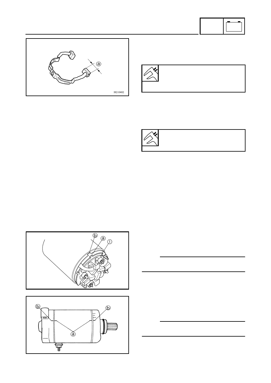
5.Measure:

Brush length 

a

 (each)

Out of specification 

 Replace the brush

holder set. 

Brush length:

12.5 mm (0.49 in)

<Wear limit:>

5 mm (0.20 in)

6.Measure:

Brush spring force
Fatigue/out of specification 

 Replace the

brush holder set. 

Brush spring force:

7.65 ~ 10.01 Nm
(780 ~ 1,020 g, 27.54 ~ 36.03 oz)

7.Check:

O-rings
Wear/damage 

 Replace.

ASSEMBLING THE STARTER MOTOR

1.Install:

Brush holder set 

1


NOTE:

Align the projection 

a

 on the brush seat 1 with

the slot 

b

 on the yoke.

2.Install:

Yoke 

Brackets

NOTE:

Align the match marks 

a

 on the yoke with the

match marks 

b

 on the brackets.

9 - 22

+

ELEC

CHARGING SYSTEM

EB804000

CHARGING SYSTEM

CIRCUIT DIAGRAM 

W

/

B

B

B

/

R

B

/

R

B

W

/

B

C

D

OB

BO

LB

BL

YB

r

BB

B

/

Y

B

BB

(GRA

Y)

(GRA

Y)

D

WIRE HARNESS

SUB-WIRE 

HARNESS 4

Br

Sb

L

/

B

R

/

B

Br

/

B

B

/

Y

L

/

B

Sb

Br

B

/

Y

Br

/

B

R

/

B

Br

Y

L

L

/

B

GB

LY

R

/

Y

BG

L

/

B

WS

b

G

/

L

L

/

WB

/

RW

/

L

G

/

L

Sb

W

W

/

LB

/

RL

/

W

W

/

R

Sb

L

/

WG

/

W

Sb

W

/

R

G

/

WL

/

W

W

/

B

L

/

Y

Br

W

/

R

L

/

Y

W

/

B

W

/

R

Br

W

/

G

R

W

/

RW

/

G

R

W

/

G

W

/

L

W

/

R

RB

r

R

Br

/

L

Br

R

Br

/

L

R

L

/

GL

/

R

L

/

B

Sb

L

/

RL

/

G

Sb

L

/

B

R

L

/

WL

/

B

R

/

BL

/

W

OB

B

/

Y

R

W

/

RW

/

G

W

Y

/

B

B

/

RG

/

L

G

/

WW

/

B

Sb

G

/

R

(BLA

CK)

(BLA

CK)

(BLA

CK)

C

WIRE HARNESS

SUB-WIRE 

HARNESS 3

B

WIRE HARNESS

SUB-WIRE 

HARNESS 2

A

WIRE HARNESS

SUB-WIRE 

HARNESS 1

(BLA

CK)

(BLA

CK)

(BLA

CK)

(GRA

Y)

(GRA

Y)

(GRA

Y)

(GRA

Y)

(BLA

CK)

(BLA

CK)

Gy

G

/

R

Br

B

G

/

R

Gy

BB

r

(GRA

Y)

(GRA

Y)

W

WW

W

WW

OFF

ON

OFF

2WD

4WD

LOCK

W

/

G

Br

/

L

R

/

G

L

/

B

G

/

W

G

/

W

L

/

W

Br

Br

W

/

R

W

/

G

R

W

/

G

W

/

R

L

/

W

L

/

Y

R

/

B

G

/

W

Y

/

B

G

/

R

Sb

G

/

L

W

/

B

B

/

R

B

/

Y

B

/

Y

L

/

Y

R

/

G

Br

/

R

B

/

R

W

/

B

G

/

L

G

/

R

W

/

L

W

/

L

R

Br

Sb

O

C

B

O

B

W

W

B

B

B

W

B

W

W

W

W

W

W

R

R

R

R

B

WW

W

R

B

B

PUSH

_

R

R

B

B

B

B

B

B

R

R

R

D

W

/

R

W

/

R

D

L

/

W

B

/

R

B

/

R

L

/

W

D

A

Br

/

B

Br

/

B

Br

/

B

B

B

W

/

B

W

/

B

W

/

B

A

Sb

Sb

O

/

R

P

B

/

W

L

/

Y

W

B

G

/

R

R

/

G

B

G

/

RR

/

G

B

Y

G

B

YG

B

YG

B

B

/

Y

Br

/

R

Br

/

R

L

/

R

B

(BLACK)

Br

/

B

Br

/

R

Br

/

R

L

/

G

B

(BLACK)

Br

/

R

L

/

R

B

/

Y

Br

/

R

B

Br

/

R

L

/

G

Br

/

B

B

B

B

B

B

Br

Sb

L

/

B

L

/

G

Br

B

/

Y

Sb

L

/

B

B

/

Y

L

/

R

Y

/

B

Br

/

R

L

/

R

Gy

Gy

G

/

R

Br

/

B

W

/

B

B

B

/

YB

/

R

B

L

/

B

Sb

Br

B

B

B

B

A

Y

/

B

Gy

Br

/

R

L

/

R

Br

/

L

Br

/

R

Br

/

L

L

/

B

R

/

B

Br

/

L

R

/

W

R

/

W

Br

/

L

R

/

Y

Br

/

L

Br

R

/

B

R

/

B

R

/

Y

P

B

B

B

G
Y

G
Y

B

L

L

L

PUSH

_

Br

B

B

P

(BLACK)

(BLACK)

R

/

B

R

/

W

R

/

B

R

/

W

B

G
Y

B

L
Y

Y

G

B

(DARK GRAY)

(BLACK)

(BLACK)

L

R

/

B

Br

Y

YB

r

BB

(BLACK)

(BLACK)

Br

Y

Br

B

Br

B

1

2

3

4

5

6

7

8

9

0

A

B

C

D

E

F

G

HI

J

K

L

M

O

P

Q

R

ST

U

V

W

Y

\

]

b

d

e

i

g

j

k

h

b

^a

X

Z

[

c

f

N

1

A.C. magneto

2

Rectifier/regulator

5

Battery

6

Main fuse

9 - 23

+

ELEC

CHARGING SYSTEM

EB804010

TROUBLESHOOTING

Procedure

Check:
1.Fuse (main)
2.Battery
3.Charging voltage

IF THE BATTERY IS NOT CHARGED:

4.Charging coil resistance
5.Wiring connections 

(the entire charging system)

NOTE:

Remove the following part(s) before
troubleshooting:

1)Seat
2)Fuel tank side panels

Use the following special tool(s) for
troubleshooting.

Inductive tachometer:

P/N. YU-8036-A

Engine tachometer:

P/N. 90890-03113

Pocket tester:

P/N. YU-03112, 90890-03112

EB802011

CONTINUITY

1.Fuse (main)

Refer to “CHECKING THE SWITCH”.

NO CONTINUITY

Replace the fuse.

EB802012

CORRECT

2.Battery

Check the battery condition.
Refer to “CHECKING THE BATTERY” in
CHAPTER 3.

Open-circuit voltage:

12.8 V or more at 20 °C (68 °F)

INCORRECT

Clean the battery terminals.

Recharge or replace the battery.

EB804011

3.Charging voltage

Connect the engine tachometer to the
spark plug lead #1.

Connect the pocket tester (DC 20 V) to the
battery.

Tester (+) lead 

 Battery (+) terminal

Tester (–) lead 

 Battery (–) terminal

9 - 24

+

ELEC

CHARGING SYSTEM

OUT OF
SPECIFICATION 

Start the engine and accelerate to about
3,000 r/min.

Charging voltage:

14 V at 3,000 r/min

NOTE:

Use a fully charged battery.

MEETS SPECIFICATION

The charging circuit is not faulty.

EB804012

MEETS
SPECIFICATION

4.Charging coil resistance

Disconnect the AC magneto coupler from
the wire harness.

Connect the pocket tester (


×

 1) to the

charging coils.

Tester (+) lead 

 White terminal 

1


Tester (–) lead 

 White terminal 

2


Tester (+) lead 

 White terminal 

1


Tester (–) lead 

 White terminal 

3


Measure the stator coil resistance.

Charging coil resistance:

0.41 ~ 0.61 

 at 20 °C (68 °F)

OUT OF SPECIFICATION

Replace the pickup coil/stator assembly.

EB804015

CORRECT

5.Wiring connections

Check the connections of the entire
charging system.
Refer to “CIRCUIT DIAGRAM”.

Replace the rectifier/regulator.

POOR CONNECTION

Properly connect the charging system.

9 - 25

+

ELEC

LIGHTING SYSTEM

EB805000

LIGHTING SYSTEM

CIRCUIT DIAGRAM

OFF

W

/

B

B

B

/

R

B

/

R

B

W

/

B

C

D

OB

BO

LB

BL

YB

r

BB

B

/

Y

B

BB

(GRA

Y)

(GRA

Y)

D

WIRE HARNESS

SUB-WIRE 

HARNESS 4

Br

Sb

L

/

B

R

/

B

Br

/

B

B

/

Y

L

/

B

Sb

Br

B

/

Y

Br

/

B

R

/

B

Br

Y

L

L

/

B

GB

LY

R

/

Y

BG

L

/

B

WS

b

G

/

L

L

/

WB

/

RW

/

L

G

/

L

Sb

W

W

/

LB

/

RL

/

W

W

/

R

Sb

L

/

WG

/

W

Sb

W

/

R

G

/

WL

/

W

W

/

B

L

/

Y

Br

W

/

R

L

/

Y

W

/

B

W

/

R

Br

W

/

G

R

W

/

RW

/

G

R

W

/

G

W

/

L

W

/

R

RB

r

R

Br

/

L

Br

R

Br

/

L

R

L

/

GL

/

R

L

/

B

Sb

L

/

RL

/

G

Sb

L

/

B

R

L

/

WL

/

B

R

/

BL

/

W

OB

B

/

Y

R

W

/

RW

/

G

W

Y

/

B

B

/

RG

/

L

G

/

WW

/

B

Sb

G

/

R

(BLA

CK)

(BLA

CK)

(BLA

CK)

C

WIRE HARNESS

SUB-WIRE 

HARNESS 3

B

WIRE HARNESS

SUB-WIRE 

HARNESS 2

A

WIRE HARNESS

SUB-WIRE 

HARNESS 1

(BLA

CK)

(BLA

CK)

(BLA

CK)

(GRA

Y)

(GRA

Y)

(GRA

Y)

(GRA

Y)

(BLA

CK)

(BLA

CK)

Gy

G

/

R

Br

B

G

/

R

Gy

BB

r

(GRA

Y)

(GRA

Y)

W

WW

W

WW

OFF

ON

OFF

2WD

4WD

LOCK

W

/

G

Br

/

L

R

/

G

L

/

B

G

/

W

G

/

W

L

/

W

Br

Br

W

/

R

W

/

G

R

W

/

G

W

/

R

L

/

W

L

/

Y

R

/

B

G

/

W

Y

/

B

G

/

R

Sb

G

/

L

W

/

B

B

/

R

B

/

Y

B

/

Y

L

/

Y

R

/

G

Br

/

R

B

/

R

W

/

B

G

/

L

G

/

R

W

/

L

W

/

L

R

Br

Sb

O

C

B

O

B

W

W

B

B

B

W

B

W

W

W

W

W

W

R

R

R

R

B

WW

W

R

B

B

PUSH

_

R

R

B

B

B

B

B

B

R

R

R

D

W

/

R

W

/

R

D

L

/

W

B

/

R

B

/

R

L

/

W

D

A

Br

/

B

Br

/

B

Br

/

B

B

B

W

/

B

W

/

B

W

/

B

A

Sb

Sb

O

/

R

P

B

/

W

L

/

Y

W

B

G

/

R

R

/

G

B

G

/

RR

/

G

B

Y

G

B

YG

B

YG

B

B

/

Y

Br

/

R

Br

/

R

L

/

R

B

(BLACK)

Br

/

B

Br

/

R

Br

/

R

L

/

G

B

(BLACK)

Br

/

R

L

/

R

B

/

Y

Br

/

R

B

Br

/

R

L

/

G

Br

/

B

B

B

B

B

B

Br

Sb

L

/

B

L

/

G

Br

B

/

Y

Sb

L

/

B

B

/

Y

L

/

R

Y

/

B

Br

/

R

L

/

R

Gy

Gy

G

/

R

Br

/

B

W

/

B

B

B

/

YB

/

R

B

L

/

B

Sb

Br

B

B

B

B

A

Y

/

B

Gy

Br

/

R

L

/

R

Br

/

L

Br

/

R

Br

/

L

L

/

B

R

/

B

Br

/

L

R

/

W

R

/

W

Br

/

L

R

/

Y

Br

/

L

Br

R

/

B

R

/

B

R

/

Y

P

B

B

B

G
Y

G
Y

B

L

L

L

PUSH

_

Br

B

B

P

(BLACK)

(BLACK)

R

/

B

R

/

W

R

/

B

R

/

W

B

G
Y

B

L
Y

Y

G

B

(DARK GRAY)

(BLACK)

(BLACK)

L

R

/

B

Br

Y

YB

r

BB

(BLACK)

(BLACK)

Br

Y

Br

B

Br

B

1

2

3

4

5

6

7

8

9

0

A

B

C

D

E

F

G

HI

J

K

L

M

O

P

Q

R

ST

U

V

W

Y

\

]

b

d

e

i

g

j

k

h

b

^a

X

Z

[

c

f

N

3

Main switch

5

Battery

6

Ma

in

 fu

se

[

Headlight fus

e

]

Light

 sw

itch

b

Headlight

i

T

a

il/

br

ake ligh

t

9 - 26

+

ELEC

LIGHTING SYSTEM

EB805010

TROUBLESHOOTING

Procedure

Check:
1.Fuse (main, headlight)
2.Battery
3.Main switch

IF THE HEADLIGHT AND/OR TAILLIGHT FAIL TO COME ON:

4.Light switch
5.Wiring connections 

(the entire lighting system)

NOTE:

Remove the following part(s) before
troubleshooting:

1)Seat
2)Front carrier
3)Front fender panel

Use the following special tool(s) for
troubleshooting.

Pocket tester:

P/N. YU-03112, 90890-03112

EB802011

CONTINUITY

1.Fuse (main, headlight)

Refer to “CHECKING THE SWITCH”.

NO CONTINUITY

Replace the fuse.

EB802012

CORRECT

2.Battery

Check the battery condition.
Refer to “CHECKING THE BATTERY” in
CHAPTER 3.

Open-circuit voltage:

12.8 V or more at 20 °C (68 °F)

*

INCORRECT

Clean the battery terminals.

Recharge or replace the battery.

9 - 27

+

ELEC

LIGHTING SYSTEM

C0NTINUITY

CORRECT

3.Main switch

Refer to “CHECKING THE SWITCH”.

*

INCORRECT 

Replace the main switch.

CORRECT

4.Light switch

Refer to “CHECKING THE SWITCH”.

INCORRECT

Light switch is faulty, replace the handlebar
switch (left).

EB805013

CORRECT

5.Wiring connection 

Check the connections of the entire lighting
system.
Refer to “WIRING DIAGRAM”.

Check the condition of each of the lighting
system’s circuits.
Refer to “CHECKING THE LIGHTING
SYSTEM”.

POOR CONNECTION

Properly connect the lighting system.

9 - 28

+

ELEC

LIGHTING SYSTEM

EB805020

CHECKING THE LIGHTING SYSTEM

1.If the headlights fail to come on:

CONTINUITY

1.Bulb and bulb socket

Check the bulb and bulb socket for
continuity.

NO CONTINUITY

Replace the bulb and/or bulb socket.

2.Voltage

Connect the pocket tester (DC 20 V) to the
headlight couplers.

Tester (+) lead 


Green terminal 

1

 or Yellow terminal 

2


Tester (–) lead 

 Black terminal 

3


È

When the light switch is on “

”.

É

When the light switch is on “

”.

È

É

MEETS
SPECIFICATION

Turn the main switch to “ON”.

Turn the light switch to “

” or “

”.

Check the voltage (12 V) of the “Green”
and  “Yellow” leads on the bulb socket
connector.

This circuit is not faulty.

OUT OF SPECIFICATION

The wiring circuit from the main switch to the
bulb socket connector is faulty, repair it.

9 - 29

+

ELEC

LIGHTING SYSTEM

EB805021

2.If the taillight fails to come on:

CONTINUITY

1.Bulb and bulb socket

Check the bulb and bulb socket for
continuity.

NO CONTINUITY

Replace the bulb and/or bulb socket.

2.Voltage

Connect the pocket tester (20 V) to the bulb
socket coupler.

Tester (+) lead 

 Blue lead 

1


Tester (–) lead 

 Black lead 

2


L

Y

B

1

2

MEETS
SPECIFICATION

Turn the main switch to “ON”.

Turn the light switch to “

” or “

”.

Check the voltage (12 V) of the “Blue” lead
on the bulb socket connector.

This circuit is not faulty.

OUT OF SPECIFICATION

The wiring circuit from the main switch to the
bulb socket connector is faulty, repair it.

9 - 30

+

ELEC

SIGNAL SYSTEM

EB806000

SIGNAL SYSTEM

CIRCUIT DIAGRAM

2WD

4WD

LOCK

W

/

B

B

B

/

R

B

/

R

B

W

/

B

C

D

OB

BO

LB

BL

YB

r

BB

B

/

Y

B

BB

(GRA

Y)

(GRA

Y)

D

WIRE HARNESS

SUB-WIRE 

HARNESS 4

Br

Sb

L

/

B

R

/

B

Br

/

B

B

/

Y

L

/

B

Sb

Br

B

/

Y

Br

/

B

R

/

B

Br

Y

L

L

/

B

GB

LY

R

/

Y

BG

L

/

B

WS

b

G

/

L

L

/

WB

/

RW

/

L

G

/

L

Sb

W

W

/

LB

/

RL

/

W

W

/

R

Sb

L

/

WG

/

W

Sb

W

/

R

G

/

WL

/

W

W

/

B

L

/

Y

Br

W

/

R

L

/

Y

W

/

B

W

/

R

Br

W

/

G

R

W

/

RW

/

G

R

W

/

G

W

/

L

W

/

R

RB

r

R

Br

/

L

Br

R

Br

/

L

R

L

/

GL

/

R

L

/

B

Sb

L

/

RL

/

G

Sb

L

/

B

R

L

/

WL

/

B

R

/

BL

/

W

OB

B

/

Y

R

W

/

RW

/

G

W

Y

/

B

B

/

RG

/

L

G

/

WW

/

B

Sb

G

/

R

(BLA

CK)

(BLA

CK)

(BLA

CK)

C

WIRE HARNESS

SUB-WIRE 

HARNESS 3

B

WIRE HARNESS

SUB-WIRE 

HARNESS 2

A

WIRE HARNESS

SUB-WIRE 

HARNESS 1

(BLA

CK)

(BLA

CK)

(BLA

CK)

(GRA

Y)

(GRA

Y)

(GRA

Y)

(GRA

Y)

(BLA

CK)

(BLA

CK)

Gy

G

/

R

Br

B

G

/

R

Gy

BB

r

(GRA

Y)

(GRA

Y)

W

WW

W

WW

OFF

ON

OFF

2WD

4WD

LOCK

W

/

G

Br

/

L

R

/

G

L

/

B

G

/

W

G

/

W

L

/

W

Br

Br

W

/

R

W

/

G

R

W

/

G

W

/

R

L

/

W

L

/

Y

R

/

B

G

/

W

Y

/

B

G

/

R

Sb

G

/

L

W

/

B

B

/

R

B

/

Y

B

/

Y

L

/

Y

R

/

G

Br

/

R

B

/

R

W

/

B

G

/

L

G

/

R

W

/

L

W

/

L

R

Br

Sb

O

C

B

O

B

W

W

B

B

B

W

B

W

W

W

W

W

W

R

R

R

R

B

WW

W

R

B

B

PUSH

_

R

R

B

B

B

B

B

B

R

R

R

D

W

/

R

W

/

R

D

L

/

W

B

/

R

B

/

R

L

/

W

D

A

Br

/

B

Br

/

B

Br

/

B

B

B

W

/

B

W

/

B

W

/

B

A

Sb

Sb

O

/

R

P

B

/

W

L

/

Y

W

B

G

/

R

R

/

G

B

G

/

RR

/

G

B

Y

G

B

YG

B

YG

B

B

/

Y

Br

/

R

Br

/

R

L

/

R

B

(BLACK)

Br

/

B

Br

/

R

Br

/

R

L

/

G

B

(BLACK)

Br

/

R

L

/

R

B

/

Y

Br

/

R

B

Br

/

R

L

/

G

Br

/

B

B

B

B

B

B

Br

Sb

L

/

B

L

/

G

Br

B

/

Y

Sb

L

/

B

B

/

Y

L

/

R

Y

/

B

Br

/

R

L

/

R

Gy

Gy

G

/

R

Br

/

B

W

/

B

B

B

/

YB

/

R

B

L

/

B

Sb

Br

B

B

B

B

A

Y

/

B

Gy

Br

/

R

L

/

R

Br

/

L

Br

/

R

Br

/

L

L

/

B

R

/

B

Br

/

L

R

/

W

R

/

W

Br

/

L

R

/

Y

Br

/

L

Br

R

/

B

R

/

B

R

/

Y

P

B

B

B

G
Y

G
Y

B

L

L

L

PUSH

_

Br

B

B

P

(BLACK)

(BLACK)

R

/

B

R

/

W

R

/

B

R

/

W

B

G
Y

B

L
Y

Y

G

B

(DARK GRAY)

(BLACK)

(BLACK)

L

R

/

B

Br

Y

YB

r

BB

(BLACK)

(BLACK)

Br

Y

Br

B

Br

B

1

2

3

4

5

6

7

8

9

0

A

B

C

D

E

F

G

HI

J

K

L

M

O

P

Q

R

ST

U

V

W

Y

\

]

b

d

e

i

g

j

k

h

b

^a

X

Z

[

c

f

N

9 - 31

+

ELEC

SIGNAL SYSTEM

3

Main switch

4

Backup fuse

5

Battery

6

Main fuse

9

Reverse switch

0

CDI unit

D

Speed sensor

E

Thermo switch 1

G

Multi-function meter

H

Differential gear lock indicator light

I

Coolant temperature warning light

J

Reverse indicator light

K

Neutral indicator light

L

Park indicator light

M

High-range indicator light

N

Low-range indicator light

O

Low-range switch

P

High-range switch

Q

Neutral switch

V

On-command four-wheel drive switch and differential gear lock switch

W

Gear motor

Z

Ignition fuse

f

Signaling system fuse

g

Front brake light switch 

h

Rear brake light switch

i

Tail/brake light

j

Horn switch

k

Horn

È

For Europe and Oceania

9 - 32

+

ELEC

SIGNAL SYSTEM

EB806010

TROUBLESHOOTING

Procedure

Check:
1.Fuse (main, backup, ignition, signaling system)
2.Battery
3.Main switch
4.Wiring connections 

(the entire signal system)

IF THE BRAKE LIGHT AND/OR INDICATOR LIGHT FAILS TO COME ON:
IF THE HORN FAILS TO SOUND:

NOTE:

Remove the following part(s) before
troubleshooting:

1)Seat
2)Fuel tank
3)Air filter case
4)Front carrier
5)Front fender panel

Use the following special tool(s) for
troubleshooting.

Pocket tester:

P/N. YU-03112, 90890-03112

EB802011

CONTINUITY

1.Fuse (main, backup, ignition, signaling system)

Refer to “CHECKING THE SWITCH”.

NO CONTINUITY

Replace the fuse.

EB802012

CORRECT

2.Battery

Check the battery condition.
Refer to “CHECKING THE BATTERY” in
CHAPTER 3.

Open-circuit voltage:

12.8 V or more at 20 °C (68 °F)

*

INCORRECT

Clean the battery terminals.

Recharge or replace the battery.

9 - 33

+

ELEC

SIGNAL SYSTEM

C0NTINUITY


CORRECT

3.Main switch

Refer to “CHECKING THE SWITCH”.

*

INCORRECT 

Replace the main switch.

EB806011

CORRECT

4.Wiring connections

Check the connections of the entire signal
system.
Refer to “CIRCUIT DIAGRAM”.

Check the condition of each of the signal
system’s circuits. 
Refer to “CHECKING THE SIGNAL
SYSTEM”.

POOR CONNECTION

Properly connect the signal system.

9 - 34

+

ELEC

SIGNAL SYSTEM

CHECKING THE SIGNAL SYSTEM

1.If the brake light fails to come on:

CONTINUITY

1.Bulb and bulb socket

Check the bulb and bulb socket for
continuity.

NO CONTINUITY

Replace the bulb and/or bulb socket.

CONTINUITY

2.Brake light switches

Refer to “CHECKING THE SWITCH”.

NO CONTINUITY

Replace the brake light switch.

3.Voltage

Connect the pocket tester (DC 20 V) to the
bulb socket connector.

Tester (+) lead 

 Yellow terminal 

1


Tester (–) lead 

 Black terminal 

2


MEETS
SPECIFICATION

Turn the main switch to “ON”.

Pull in the brake lever or push down on the
brake pedal.

Check the voltage (12 V) of the “Yellow”
lead on the bulb socket connector.

This circuit is not faulty.

OUT OF SPECIFICATION

The wiring circuit from the main switch to the
bulb socket connector is faulty, repair it.

9 - 35

+

ELEC

SIGNAL SYSTEM

EB806024

2.If the indicator lights fails to come on:

CONTINUITY

1.Neutral switch

Refer to “CHECKING THE SWITCH”.

NO CONTINUITY

Replace the neutral switch.

CONTINUITY

2.High-range switch

Refer to “CHECKING THE SWITCH”.

NO CONTINUITY

Replace the high-range switch.

CONTINUITY

3.Low-range switch

Refer to “CHECKING THE SWITCH”.

NO CONTINUITY

Replace the low-range switch.

CONTINUITY

4.Reverse switch

Refer to “CHECKING THE SWITCH”.

NO CONTINUITY

Replace the reverse switch.

CONTINUITY

5.Four-wheel drive switch

Refer to “CHECKING THE SWITCH”.

Replace the meter assembly.

NO CONTINUITY

Replace the four-wheel drive switch.

9 - 36

+

ELEC

SIGNAL SYSTEM

3.If the coolant temperature warning light does not come on:

Check that the light comes on when the main switch is set to “ON”.

Check that the light comes on when the coolant temperature is 120 ± 3 °C (248 ± 5.4 °F) or higher
and that the light remains on when the coolant temperature drops to 113 °C (235.4 °F).

GOOD
CONDITION

1.Thermo switch 1

Remove the thermo switch 1 from the
cylinder head.

Connect the pocket tester (


×

 1) to the

thermo switch 1 

1

.

Immerse the thermo switch 1 in coolant 

2

.

Check the thermo switch 1 for continuity.
While heating the coolant use a thermometer

3

 to record the temperatures.

Test 
step

Coolant temperature

Continuity

Thermo switch 1

1

Less than 120 ± 3 °C

(248 ± 5.4 °F)

NO

2

More than 120 ± 3 °C

(248 ± 5.4 °F)

YES

3

More than 113 °C

(235.4 °F)

YES

4

Less than 113 °C 

(235.4 °F)

NO

Test steps 1 & 2: Heating phase
Test steps 3 & 4: Cooling phase

È

The thermo switch 1 circuit is open and the
coolant temperature warning light is off.

É

The thermo switch 1 circuit is closed and the
coolant temperature warning light is come on.

WARNING

Handle the thermo switch 1 with special
care.
Never subject it to a strong shock or allow
it to be dropped. Should it be dropped, it
must be replaced.

T


R

.

.

Thermo switch 1:

8 Nm (0.8 m • kg, 5.8 ft • lb)
Three bond sealock

®

 #10

Replace the meter assembly.

É

È

113 ˚C

(235.4 ˚F)

120 ± 3 ˚C

(248 ± 5.4 ˚F)

BAD CONDITION

Replace the thermo switch 1.


Content      ..     21      22      23      24     ..