Yamaha YFM45FAR, YFM450FAR. Service Manual - part 18


  Index      Manuals     Yamaha YFM45FAR, YFM450FAR. Service Manual


Search            copyright infringement  


Content      ..     16      17      18      19     ..


Yamaha YFM45FAR, YFM450FAR. Service Manual - part 18


7 - 29

DRIV

REAR AXLE/FINAL DRIVE GEAR AND DRIVE SHAFT

Final gear lash adjustment
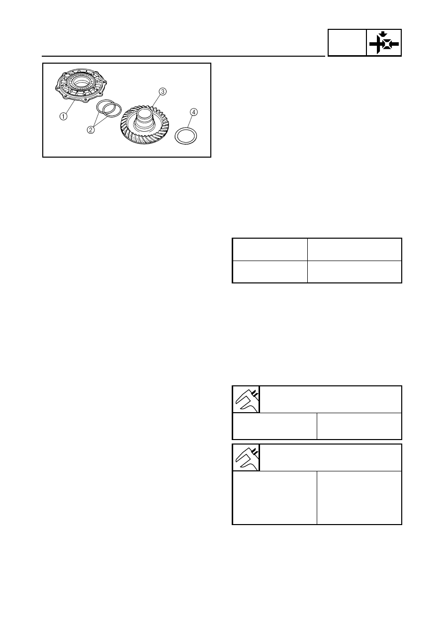
1.Remove:

Bearing housing 

1


Ring gear shim(s) 

2


Ring gear 

3


Thrust washer 

4


2.Adjust:

Gear lash

*****************************************************

Adjustment steps:

Select a suitable shim(s) and thrust
washer(s) using the following chart.

If increased by more than 0.2 mm (0.008 in):
Reduce the thrust washer thickness by
0.2 mm (0.008 in) for every 0.2 mm
(0.008 in) of ring gear shim increase.

If reduced by more than 0.2 mm (0.008 in):
Increase the thrust washer thickness by
0.2 mm (0.008 in) for every 0.2 mm
(0.008 in) that the ring gear shim is
decreased.

*****************************************************

Too little gear lash

Reduce shim 
thickness.

Too large gear lash

Increase shim 
thickness.

Ring gear shim

Thickness (mm)

0.25

0.30

0.35

0.40

0.45

0.50

Thrust washer

Thickness (mm)

1.0

1.1

1.2

1.3

1.35

1.4

1.45

1.5

1.55

1.6

1.7

1.8

1.9

2.0

2.1

7 - 30

DRIV

REAR AXLE/FINAL DRIVE GEAR AND DRIVE SHAFT

ASSEMBLING THE FINAL DRIVE GEAR 

1.Install:

Drive pinion gear (with shim(s) and bearing)
(proper shim size as calculated)

Bearing retainer (drive pinion gear) 

1


Use a bearing retainer wrench 

2

.

CAUTION:

Always use a new bearing.

The final drive shaft bearing retainer has
left-hand threads. Turn the retainer
counterclockwise to tighten it.

2.Adjust:

Final gear lash
Refer to “MEASUREMENT AND
ADJUSTING THE FINAL GEAR LASH”.

Bearing retainer wrench:

P/N. YM-04050, 90890-04050

T


R

.

.

100 Nm (10.0 m • kg, 72 ft • lb)

INSTALLING THE FINAL DRIVE GEAR 

1.Lubricate:

Drive shaft

Coupling gear

O-ring

Oil seal

Bearing

2.Install:

Drive shaft 

1


(to the universal joint)

Lithium-soap-based grease

7 - 31

DRIV

REAR AXLE/FINAL DRIVE GEAR AND DRIVE SHAFT

3.Apply:

Sealant (Quick Gasket

®

)

(to the mating surfaces of the swingarm and
the final drive gear case)

Sealant (Quick gasket

®

):

P/N. ACC-11001-05-01

Yamaha bond No.1215:

P/N. 90890-85505

4.Install:

Final drive gear

Nuts 

Bolts 

LT

T


R

.

.

63 Nm (6.3 m • kg, 45 ft • lb)

LT

T


R

.

.

63 Nm (6.3 m • kg, 45 ft • lb)

5.Install:

Dust cover

Rear axle

*****************************************************

Installation steps:

Install the dust cover 

1

 onto the rear axle.

NOTE:

Adjust the length 

a

 to 210.1 mm (8.3 in) when

install the dust cover.

Install the rear axle (with dust cover) 

2

.

Install the rear brake disc and rear wheel hub
(left).

Temporarily tighten the left axle nut 

3

.

NOTE:

After tightening the rear axle nut 

3

, the

position of the dust cover 

1

 will slightly move

to protect the oil seal of the final gear case.

*****************************************************

CHAS

8

CHAS

CHAPTER 8.

CHASSIS

FRONT AND REAR WHEELS 

..................................................................... 8-1

FRONT WHEELS .................................................................................. 8-1
REAR WHEELS  .................................................................................... 8-2
CHECKING THE WHEEL  ..................................................................... 8-3
CHECKING THE WHEEL HUB ............................................................. 8-3
CHECKING THE BRAKE DISC  ............................................................ 8-4
INSTALLING THE WHEEL HUB ........................................................... 8-4
INSTALLING THE WHEEL  ................................................................... 8-4

FRONT AND REAR BRAKES 

...................................................................... 8-6

FRONT BRAKE PADS  .......................................................................... 8-6
REAR BRAKE PADS  ............................................................................ 8-7
REPLACING THE FRONT BRAKE PAD  .............................................. 8-8
REPLACING THE REAR BRAKE PAD ............................................... 8-10
FRONT BRAKE MASTER CYLINDER ................................................ 8-12
REAR BRAKE MASTER CYLINDER  .................................................. 8-14
CHECKING THE MASTER CYLINDER  .............................................. 8-17
ASSEMBLING THE FRONT BRAKE MASTER CYLINDER  ............... 8-18
ASSEMBLING THE REAR BRAKE MASTER CYLINDER  ................. 8-18
INSTALLING THE FRONT BRAKE MASTER CYLINDER  ................. 8-19
INSTALLING THE REAR BRAKE MASTER CYLINDER  .................... 8-20
FRONT BRAKE CALIPER  .................................................................. 8-22
REAR BRAKE CALIPER ..................................................................... 8-24
DISASSEMBLING THE FRONT AND REAR BRAKE CALIPER  ........ 8-26
CHECKING THE FRONT AND REAR BRAKE CALIPER ................... 8-26
ASSEMBLING THE FRONT AND REAR BRAKE CALIPER  .............. 8-27
INSTALLING THE FRONT BRAKE CALIPER  .................................... 8-27
INSTALLING THE REAR BRAKE CALIPER ....................................... 8-29

STEERING SYSTEM 

.................................................................................. 8-30

HANDLEBAR ...................................................................................... 8-30
REMOVING THE REAR BRAKE SWITCH  ......................................... 8-31
CHECKING THE HANDLEBAR  .......................................................... 8-31
INSTALLING THE HANDLEBAR  ........................................................ 8-31
INSTALLING THE REAR BRAKE LEVER  .......................................... 8-31
INSTALLING THE MASTER CYLINDER ASSEMBLY ........................ 8-32
STEERING STEM  ............................................................................... 8-33
REMOVING THE BEARING RETAINER  ............................................ 8-35
CHECKING THE STEERING STEM ................................................... 8-35
INSTALLING THE BEARING RETAINER ........................................... 8-35
INSTALLING THE CABLE GUIDE  ...................................................... 8-35
TIE ROD AND STEERING KNUCKLE ................................................ 8-36
REMOVING THE STEERING KNUCKLE  ........................................... 8-38
CHECKING THE TIE ROD .................................................................. 8-38
CHECKING THE STEERING KNUCKLE ............................................ 8-38
INSTALLING THE TIE ROD ................................................................ 8-41

CHAS

FRONT ARMS AND FRONT SHOCK ABSORBER 

.................................. 8-42

REMOVING THE FRONT ARMS ........................................................ 8-44
CHECKING THE FRONT ARM ........................................................... 8-44
CHECKING THE FRONT SHOCK ABSORBER  ................................. 8-46
INSTALLING THE FRONT ARMS 

AND FRONT SHOCK ABSORBER ................................................. 8-47

REAR SHOCK ABSORBER AND SWINGARM 

........................................ 8-48

REMOVING THE SWINGARM  ........................................................... 8-50
CHECKING THE REAR SHOCK ABSORBER  ................................... 8-50
CHECKING THE SWINGARM  ............................................................ 8-51
CHECKING THE RUBBER BOOT  ...................................................... 8-51
INSTALLING THE RUBBER BOOT  .................................................... 8-51
INSTALLING THE REAR AXLE HOUSING  ........................................ 8-52

8 - 1

CHAS

FRONT AND REAR WHEELS

CHASSIS

FRONT AND REAR WHEELS

FRONT WHEELS

Order

Job name/Part name

Q’ty

Remarks

Removing the front wheel

Remove the parts in the order below.
Place the machine on a level surface.

WARNING

Securely support the machine so there
is no danger of it falling over.

1

Front wheel

1

Refer to “INSTALLING THE WHEEL”.

2

Wheel cap

1

Refer to “INSTALLING THE WHEEL 
HUB”.

3

Cotter pin

1

4

Axle nut

1

5

Brake caliper assembly

1

NOTE:

Do not squeeze the brake lever when the
brake caliper is off of the brake disc as
the brake pads will be forced shut.

6

Wheel hub

1

7

Brake  disc

1

For installation, reverse the removal 
procedure.

8 - 2

CHAS

FRONT AND REAR WHEELS

REAR WHEELS

Order

Job name/Part name

Q’ty

Remarks

Removing the rear wheel

Remove the parts in the order below.
Place the machine on a level surface.

WARNING

Securely support the machine so there
is no danger of it falling over.

1

Rear wheel

2

Refer to “INSTALLING THE WHEEL”.

2

Wheel cap

2

Refer to “INSTALLING THE WHEEL 
HUB”.

3

Cotter pin

2

4

Axle nut

2

5

Wheel hub

2

6

Brake caliper mounting bolt

2

7

Brake disc bracket

1

8

Brake  disc

1

9

Brake disc guard

1

For installation, reverse the removal 
procedure.

8 - 3

CHAS

FRONT AND REAR WHEELS

CHECKING THE WHEEL

1.Check:

Wheel

2.Measure:

Wheel runout
Over the specified limit 

 Replace the wheel

or check the wheel bearing play 

1

.

3.Check:

Wheel balance
Out of balance 

 Adjust.

Wheel runout limit:

Radial 

2

: 2.0 mm (0.08 in)

Lateral 

3

: 2.0 mm (0.08 in)

WARNING

After replacing the tire, ride conservatively
to allow the tire to be properly seated in the
rim. Failure to do so may cause an accident
resulting in machine damage and possible
operator injury.

CHECKING THE WHEEL HUB

1.Check:

Wheel hub 

1


Cracks/damage 

 Replace. 

Splines (wheel hub) 

2


Wear/damage 

 Replace.

8 - 4

CHAS

FRONT AND REAR WHEELS

CHECKING THE BRAKE DISC

1.Check:

Brake disc
Galling/damage 

 Replace.

2.Measure:

Brake disc deflection
Out of specification 

 Check the wheel

runout.
If wheel runout is within the limits, replace
the brake disc.

Brake disc thickness 

a


Out of specification 

 Replace.

Brake disc maximum deflection:

0.15 mm (0.006 in)

Brake disc minimum thickness:

3 mm (0.12 in)

INSTALLING THE WHEEL HUB

1.Install:

Axle nut 

Cotter pin 

1

NOTE:

Do not loosen the axle nut after torquing it. If
the axle nut groove is not aligned with the
cotter pin hole, align the groove with the hole
by tightening the axle nut.

T


R

.

.

150 Nm (15.0 m • kg, 110 ft • lb)

New

INSTALLING THE WHEEL

1.Install:

Wheel

NOTE:

The arrow mark 

1

 on the tire must point in the

direction of rotation 

È

 of the wheel.

8 - 5

CHAS

FRONT AND REAR WHEELS

2.Install:

Nuts (wheel) 

1


WARNING

Tapered wheel nuts 

1

 are used for both the

front and rear wheels. Install each nut with
its tapered side towards the wheel.

3.Tighten:

Nuts (front wheel)

Nuts (rear wheel)

NOTE:

Tighten the nuts in stages and in a crisscross
pattern.

T


R

.

.

64 Nm (6.4 m • kg, 46 ft • lb)

T


R

.

.

55 Nm (5.5 m • kg, 40 ft • lb)

8 - 6

CHAS

FRONT AND REAR BRAKES

FRONT AND REAR BRAKES

FRONT BRAKE PADS

Order

Job name/Part name

Q’ty

Remarks

Removing the front brake pads

Remove the parts in the order below.

Front wheel

Refer to “FRONT AND REAR WHEELS”.

1

Brake caliper mounting bolt

2

Refer to “REPLACING THE FRONT 
BRAKE PAD”.

2

Brake pad holding bolt

2

3

Brake pad/pad shim

2/1

4

Pad spring

1

For installation, reverse the removal 
procedure. 

8 - 7

CHAS

FRONT AND REAR BRAKES

REAR BRAKE PADS

Order

Job name/Part name

Q’ty

Remarks

Removing the rear brake pads 

Remove the parts in the order below.

Rear wheel (left)

Refer to “FRONT AND REAR WHEELS”.

1

Brake caliper mounting bolt

2

Refer to “REPLACING THE REAR 
BRAKE PAD”.

2

Brake pad holding bolt

2

3

Brake pad/insulator/pad shim

2/2/2

4

Pad spring

1

For installation, reverse the removal 
procedure. 

8 - 8

CHAS

FRONT AND REAR BRAKES

CAUTION:

Disc brake components rarely require
disassembly. DO NOT:

disassemble components unless
absolutely necessary;

use solvents on internal brake
components;

use spent brake fluid for cleaning; (use
only clean brake fluid)

allow brake fluid to come in contact with
the eyes, as this may cause eye injury;

splash brake fluid onto painted surfaces or
plastic parts, as this may cause damage;

disconnect any hydraulic connection, as
this would require the entire brake
system to be disassembled, drained,
cleaned, properly filled and bled after
reassembly.

REPLACING THE FRONT BRAKE PAD

NOTE:

It is not necessary to disassemble the brake
caliper and brake hose to replace the brake
pads.

1.Measure:

Brake pad wear limit 

a


Out of specification 

 Replace the brake

pad as a set.

Brake pad wear limit:

1 mm (0.04 in)

2.Install:

Brake pads

Brake pad spring

NOTE:

Always install new brake pads, brake pad shim
and brake pad spring as a set.

8 - 9

CHAS

FRONT AND REAR BRAKES

*****************************************************

Installation steps:

Connect a suitable hose 

1

 tightly to the

brake caliper bleed screw 

2

. Put the other

end of this hose into an open container.

Loosen the brake caliper bleed screw and,
using a finger, push the caliper piston into
the brake caliper.

Tighten the brake caliper bleed screw. 

Install new brake pads, new pad shims 

3

and a new brake pad spring.

Install the retaining bolts and brake caliper.

NOTE:

The arrow mark 

a

 on the pad shim must point

in the direction of the disc rotation.

*****************************************************

T


R

.

.

Brake caliper bleed screw:

6 Nm (0.6 m • kg, 4.3 ft • lb)

T


R

.

.

Brake pad holding bolt:

18 Nm (1.8 m • kg, 13 ft • lb)

Brake caliper mounting bolt:

30 Nm (3.0 m • kg, 22 ft • lb)

3.Check:

Brake fluid level
Refer to “CHECKING THE BRAKE FLUID
LEVEL” in CHAPTER 3.

4.Check:

Brake lever operation
Soft or spongy feeling 

 Bleed the front

brake system.
Refer to “BLEEDING THE HYDRAULIC
BRAKE SYSTEM” in CHAPTER 3.


Content      ..     16      17      18      19     ..