Yamaha YFM45FAR, YFM450FAR. Service Manual - part 17


  Index      Manuals     Yamaha YFM45FAR, YFM450FAR. Service Manual


Search            copyright infringement  


Content      ..     15      16      17      18     ..


Yamaha YFM45FAR, YFM450FAR. Service Manual - part 17


7 - 13

DRIV

FRONT CONSTANT VELOCITY JOINTS AND

DIFFERENTIAL GEAR

3.Install:

Universal joint yoke

O-ring

Washer

Nut
Use a universal joint holder 

1

.

Universal joint holder:

P/N. YM-04062, 90890-04062

LT

T


R

.

.

62 Nm (6.2 m • kg, 45 ft • lb)

4.Check:

Differential gear operation
Unsmooth operation 

 Replace the 

differential gear assembly.
Insert the double off-set joint into the
differential gear, and turn the gear back and
forth.

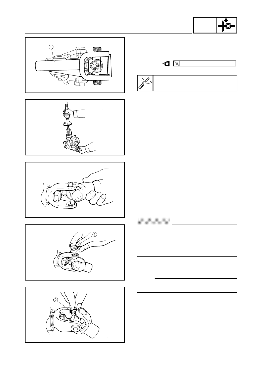
INSTALLING THE UNIVERSAL JOINT

1.Install:

Universal joint

*****************************************************

Installation steps:

Install the opposite yoke into the U-joint.

Apply wheel bearing grease to the bearings.

Install the bearing 

1

 onto the yoke.

CAUTION:

Check each bearing. The needles can
easily fall out of their races. Slide the yoke
back and forth on the bearings; the yoke
will not go all the way onto a bearing if a
needle is out of place.

Press each bearing into the U-joint using a
suitable socket.

NOTE:

The bearing must be inserted far enough into
the U-joint so that the circlip can be installed.

Install the circlips 

2

 into the groove of each

bearing.

*****************************************************

7 - 14

DRIV

MEASURING AND ADJUSTING THE 
DIFFERENTIAL GEAR LASH
Measuring the differential gear lash

1.Secure the gear case in a vise or another

supporting device.

2.Remove:

Drain plug

Gasket

3.Install:

A bolt of the specified size 

1


(into the drain plug hole)

CAUTION:

Finger tighten the bolt until it holds the ring
gear. Otherwise, the ring gear will be
damaged.

4.Attach:

Gear lash measurement tool 

1


Dial gauge 

2


a

Measuring point is 21 mm (0.83 in)

5.Measure:

Gear lash
Gently rotate the gear coupling from
engagement to engagement

.

NOTE:

Measure the gear lash at four positions. Rotate
the shaft 90° each time.

Gear lash measurement tool:

P/N. YM-01467, 90890-01467

Differential gear lash:

0.05 ~ 0.25 mm 
(0.0020 ~ 0.0098 in)

FRONT CONSTANT VELOCITY JOINTS AND

DIFFERENTIAL GEAR

7 - 15

DRIV

Adjusting differential gear lash

1.Remove:

Shim(s) (left) 

1


Differential gear assembly 

2


Shim(s) (right) 

3


2.Adjust:

Gear lash

*****************************************************

Adjustment steps:

Select the suitable shims using the following
chart.

If it is necessary to increase by more than
0.05 mm (0.002 in):
Reduce right shim thickness by 0.1 mm
(0.004 in) for every 0.1 mm (0.004 in) of left
shim increase.

If it is necessary to reduce by more than
0.1 mm (0.004 in):
Increase right shim thickness by 0.1 mm
(0.004 in) for every 0.1 mm of left shim
decreased.

* Right only

*****************************************************

Too little gear lash

Reduce shim 
thickness.

Too large gear lash

Increase shim 
thickness.

Ring gear shim (left and right)

Thickness (mm)

0.1

0.2

0.3

0.4

0.5

1.0

1.5

2.0*

2.5*

FRONT CONSTANT VELOCITY JOINTS AND

DIFFERENTIAL GEAR

7 - 16

DRIV

CHECKING THE DIFFERENTIAL GEAR 
OPERATION 

1.Block the rear wheels, and elevate the front

wheels by placing a suitable stand under the
frame.

2.Remove the wheel cap and cotter pin from

the axle nut (right or left).

3.Measure the starting torque of the front

wheel (i.e., differential gear preload) with the
torque wrench.

NOTE:

Repeat this step several times to obtain an
average figure.

During this test, the other front wheel will turn
in the opposite direction.

4.Out of specification 

 Replace the

differential gear assembly.

5.Within specification 

 Install the new cotter

pin and wheel cap.

T


R

.

.

Front wheel starting torque:
(differential gear preload):

New unit:

17 ~ 25 Nm 
(1.7 ~ 2.5 m • kg, 12 ~ 18 ft • lb)

Minimum:

10 Nm (1.0 m • kg, 7.2 ft • lb)

FRONT CONSTANT VELOCITY JOINTS AND

DIFFERENTIAL GEAR

7 - 17

DRIV

REAR AXLE/FINAL DRIVE GEAR AND DRIVE SHAFT

REAR AXLE/FINAL DRIVE GEAR AND DRIVE SHAFT

Order

Job name/Part name

Q’ty

Remarks

Removing the rear axle, final drive 
gear assembly and drive shaft 

Remove the parts in the order below.

Final gear oil

Drain.

Rear wheel hubs/brake disc

Refer to “FRONT AND REAR WHEELS” 
in CHAPTER 8.

1

O-ring

1

2

Rear axle/dust cover

1/1

Refer to “REMOVING/
INSTALLING THE 
REAR AXLE”.

3

Trailer hitch bracket

1

4

Final drive gear case breather hose

1

Disconnect.

5

Final drive gear

1

6

Drive  shaft

1

For installation, reverse the removal 
procedure.

7 - 18

DRIV

REAR AXLE/FINAL DRIVE GEAR AND DRIVE SHAFT

Order

Job name/Part name

Q’ty

Remarks

Disassembling the final drive gear 

Remove the parts in the order below.

1

Bolt

2

2

Bolt

6

3

Bearing housing

1

4

Oil seal/bearing

1/1

5

Ring gear stopper

1

6

Ring gear stopper shim

1

7

Oil seal/bearing

1/1

8

Ring gear shim

1

9

Ring gear

1

0

Thrust washer

1

NOTE:

Working in a crisscross pattern, loosen
each bolt 1/4 of a turn. After all the bolts
are loosened, remove them.

7 - 19

DRIV

REAR AXLE/FINAL DRIVE GEAR AND DRIVE SHAFT

Order

Job name/Part name

Q’ty

Remarks

A

Bearing retainer/O-ring

1/1

Refer to “DISASSEMBLING/
ASSEMBLING THE FINAL DRIVE 
GEAR”.

B

Oil seal

1

C

Final drive pinion gear

1

D

Collar

1

E

Bearing

1

F

Final drive pinion gear shim

1

G

Final drive gear case/O-ring

1/1

H

Bearing/oil seal

1/1

Refer to “REPLACING THE FINAL 
DRIVE ROLLER BEARING”.

I

Bearing

1

For assembly, reverse the disassembly 
procedure.

7 - 20

DRIV

REAR AXLE/FINAL DRIVE GEAR AND DRIVE SHAFT

REMOVING THE REAR AXLE 

1.Remove:

Rear axle 

1


(with dust seal)

O-ring

CAUTION:

Never directly tap the axle end with a
hammer, since this will result in damage
to the axle thread and spline.

Attach a suitable socket 

2

 on the axle

end and tap it with a soft hammer. Pull out
the rear axle to the right.

DISASSEMBLING THE FINAL DRIVE GEAR 

1.Remove:

Bearing retainer (final drive pinion gear)

NOTE:

Use a bearing retainer wrench 

1

.

CAUTION:

The final drive shaft bearing retainer has
left-handed threads. To loosen the retainer,
turn it clockwise.

2.Remove:

Final drive pinion gear assembly
With a soft hammer, lightly tap on the final
drive pinion gear end.

CAUTION:

Removal of the final drive pinion gear
should only be performed if gear
replacement is necessary. 

WARNING

Always use new bearings and races.

Bearing retainer wrench:

P/N. YM-04050, 90890-04050

7 - 21

DRIV

REAR AXLE/FINAL DRIVE GEAR AND DRIVE SHAFT

REPLACING THE FINAL DRIVE ROLLER 
BEARING 

1.Remove:

Roller bearing (ring gear) 

1


Use a suitable press tool 

2

 and an

appropriate support for the main housing.

Oil seal 

3


2.Remove:

Roller bearing (final drive pinion gear) 

1


*****************************************************

Removal steps:

Heat the main housing only to 150 °C
(302 °F).

Remove the roller bearing outer race with an
appropriately shaped punch 

2

.

Remove the inner race from the final drive
pinion gear.

NOTE:

The removal of the final drive pinion gear roller
bearing is difficult and seldom necessary.

*****************************************************


3.Install:

Roller bearing (final drive pinion gear)

*****************************************************

Installation steps:

Heat the main housing only to 150 °C
(302 °F).

Install the roller bearing outer race using the
proper adapter.

Install the inner race onto the drive pinion
gear.

*****************************************************
4.Install:

Oil seal 

1


Roller bearing 

2


Use a suitable press tool 

3

 and a press to

install the above components into the main
housing.

New

New

7 - 22

DRIV

REAR AXLE/FINAL DRIVE GEAR AND DRIVE SHAFT

POSITIONING THE FINAL DRIVE PINION 
GEAR AND RING GEAR 

When the final drive pinion gear, ring gear,
final gear case and/or ring gear bearing
housing are replaced, be sure to adjust the
positions of the final drive pinion gear and ring
gear using the shim(s).

Final drive pinion gear shim selection

1.Select:

Final drive pinion gear shim(s) 

1


*****************************************************

Selection steps:

To find the final drive pinion gear shim
thickness “A”, use the following formula.

a

 = a numeral (usually a decimal number)

on the final drive pinion gear either
added to or subtracted from “84”

b

 = a numeral (usually a decimal number)

on the final gear case either added to or
subtracted from “83”

Example:

1) If  “01” is stamped on the final drive

pinion gear,

a

 = 84 + 0.01 = 84.01

2) If “50” is stamped on the final gear case,

b

 = 83 + 0.50 = 83.50

3) Therefore, “A” is 0.51.

“A”= 84.01 – 83.50 

= 0.51

4) Round off the hundredth digit and select

the appropriate shim(s).
In the example above, the calculated
number is 0.51. The chart instructs you
to round off 1 to 0 at the hundredth
place. Thus, the shim thickness is
0.50 mm.

Final drive pinion gear shim thickness:

“A” = 

a

 – 

b


Hundredths

Rounded value

0, 1, 2

0

3, 4, 5, 6, 7

5

8, 9

10

7 - 23

DRIV

REAR AXLE/FINAL DRIVE GEAR AND DRIVE SHAFT

Shims are supplied in the following
thicknesses.

*****************************************************

Final drive pinion gear shim

Thickness (mm)

0.15

0.30

0.40

0.45

0.50

0.60

Ring gear shim selection

1.Select:

Ring gear shim(s) 

1


*****************************************************

Selection steps:

To find the ring gear shim thickness “B”, use
the following formula.

c

 = a numeral (usually a decimal number)

on the final gear case either added to or
subtracted from 45 

d

 = a numeral (usually a decimal number)

on the outside of the ring gear bearing
housing and added to 1

e

 = a numeral (usually a decimal number)

on the inside of the ring gear either
added to or subtracted from 35.00

f

 = bearing thickness (considered constant)

Example:

1) If “53” is stamped on the final gear case,

c

 = 45 + 0.53 = 45.53

2) If  “05” is stamped on the ring gear

bearing housing,

d

 = 1 + 0.05

= 1.05

3) If “– 05” is stamped on the ring gear,

e

 = 35 – 0.05

= 34.95

4)

f

 = 11.00.

Ring gear shim thickness:

“B” = 

c

 + 

d

 – (

e

 + 

f

)


Bearing thickness 

f

:

11.00 mm

7 - 24

DRIV

REAR AXLE/FINAL DRIVE GEAR AND DRIVE SHAFT

5) Therefore, shim thickness “B” is 0.63.

“B”= 45.53 + 1.05 – (34.95 + 11.00)

= 46.58 – 45.95
= 0.63

6) Round off the hundredth digit and select

the appropriate shim(s).
In the example above, the calculated
number is 0.63. The chart instructs you
to round off 3 to 5 at the hundredth
place.
Thus, the shim thickness is 0.65 mm.

Shims are supplied in the following
thicknesses.

*****************************************************

Hundredths

Rounded value

0, 1, 2

0

3, 4, 5, 6, 7

5

8, 9

10

Ring gear shim

Thickness (mm)

0.25

0.30

0.35

0.40

0.45

0.50

Thrust washer selection

1.Measure/select:

Ring gear thrust clearance “C”

*****************************************************

Measurement steps:

Place four pieces of Plastigauge

®

 between

the originally fitted thrust washer and the ring
gear.

Install the ring gear assembly and tighten the
bolts to specification.

NOTE:

Do not turn the drive pinion gear and ring gear
when measuring the clearance with
Plastigauge

®

.

T


R

.

.

M8 Bolts (bearing housing):

23 Nm (2.3 m • kg, 17 ft • lb)

M10 Bolts (bearing housing):

40 Nm (4.0 m • kg, 29 ft • lb)

7 - 25

DRIV

REAR AXLE/FINAL DRIVE GEAR AND DRIVE SHAFT

Remove the ring gear assembly.

Measure the thrust clearance. Calculate the
width of the flattened Plastigauge

®


1

.

If out of specification, select the correct
washer.

Ring gear thrust clearance:

0.1 ~ 0.2 mm (0.004 ~ 0.008 in)

Thrust washer selection steps:

Select a suitable thrust washer using the
following chart.

Repeat the measurement steps until the ring
gear thrust clearance is within the specified
limits.

*****************************************************

Thrust washer

Thickness (mm)

1.0

1.1

1.2

1.3

1.35

1.4

1.45

1.5

1.55

1.6

1.7

1.8

1.9

2.0

2.1

Ring gear stopper shim selection

1.Measure:

Ring gear stopper clearance “D”
Use a feeler gauge 

1

Out of specification 

 Adjust.

2

Ring gear

3

Ring gear stopper

Ring gear stopper clearance “D”:

0.30 ~ 0.60 mm (0.012 ~ 0.024 in)

7 - 26

DRIV

REAR AXLE/FINAL DRIVE GEAR AND DRIVE SHAFT

Ring gear stopper clearance adjustment

1.Remove:

Ring gear 

1


Ring gear stopper 

2


Shim(s) 

3


4

Bearing housing

È

Left-hand threads

2.Select:

Suitable shim(s) 

Shim

Thickness (mm)

0.10

0.15

0.20

0.30

0.40

0.50

3.Install:

Shim(s)

Ring gear stopper (left-hand threads)

Ring gear

NOTE:

Use LOCTITE

 on the ring gear stopper.

T


R

.

.

9 Nm (0.9 m • kg, 6.5 ft • lb)

4.Measure:

Ring gear stopper clearance 
Out of specification 

 Repeat adjustment

steps.

CHECKING THE REAR AXLE 

1.Check:

Rear axle runout 

a


Out of specification 

 Replace.

WARNING

Do not attempt to straighten a bent axle.

Ring gear stopper clearance:

0.30 ~ 0.60 mm (0.012 ~ 0.024 in)

Rear axle runout limit:

1.5 mm (0.06 in)

7 - 27

DRIV

REAR AXLE/FINAL DRIVE GEAR AND DRIVE SHAFT

CHECKING THE DRIVE SHAFT 

1.Check:

Drive shaft (splines)
Wear/damage 

 Replace.

CHECKING THE FINAL DRIVE GEAR 

1.Check:

Final gear case 

1


Bearing housing (ring gear) 

2


Cracks/damage 

 Replace.

NOTE:

When the final gear case and/or the ring gear
bearing housing are replaced, be sure to
adjust the shim of the final drive pinion gear
and/or ring gear.

2.Check:

Gear teeth
Pitting/galling/wear 

 Replace the drive

pinion gear and ring gear as a set.

Oil seals

O-rings
Damage 

 Replace.

3.Check:

Bearings
Damage 

 Replace.

NOTE:

Reusing roller bearings is acceptable, but
Yamaha recommends installing new ones.
Do not reuse the oil seal.

When the final drive pinion gear and/or ring
gear are replaced, be sure to adjust the shim
of the final drive pinion gear and/or ring gear.

7 - 28

DRIV

REAR AXLE/FINAL DRIVE GEAR AND DRIVE SHAFT

MEASUREMENT AND ADJUSTING THE 
FINAL GEAR LASH 
Final gear lash measurement

1.Secure the gear case in a vise or another

supporting device.

2.Remove:

Drain plug

Gasket

3.Install:

A bolt of the specified size 

1


(into the drain plug hole)

CAUTION:

Finger tighten the bolt until it holds the ring
gear. Otherwise, the ring gear will be
damaged.

4.Attach:

Gear lash measurement tool 

1


Dial gauge 

2


a

Measuring point is 31.46 mm (1.24 in)

Gear lash measurement tool:

P/N. YM-01475, 90890-01475

5.Measure:

Gear lash
Gently rotate the gear coupling from
engagement to engagement

.

NOTE:

Measure the gear lash at four positions. Rotate
the shaft 90° each time.

Final gear lash:

0.1 ~ 0.2 mm (0.004 ~ 0.008 in)


Content      ..     15      16      17      18     ..